Our objective is to create an interactive experience for anxious people so that they feel more calm and comfortable in stressful environments.
Our product is an anti-stress toy that is :
- Fun to play with
- Interactif
- Modular
- Portable
overall systems :
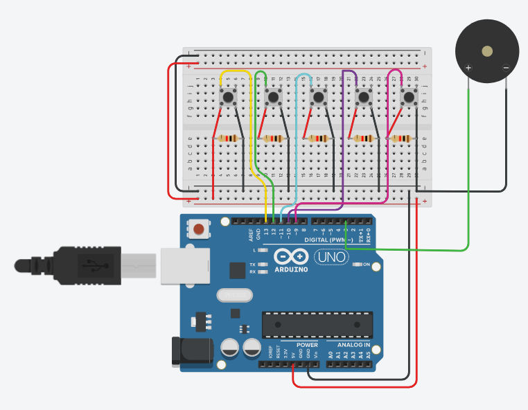
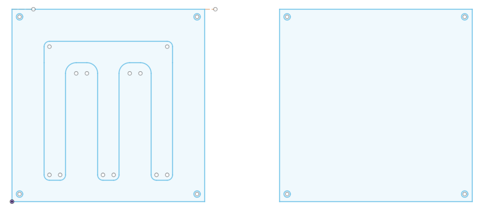
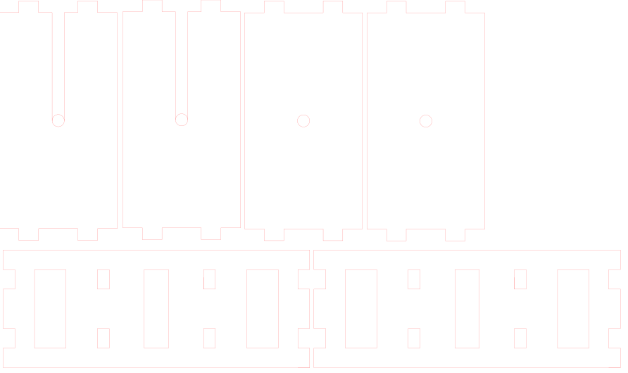
Piano
Summary :
The portable piano with 5 musical notes ( do re mi fa sol ). With this piano you can express your creative side and play nealry every song possible.
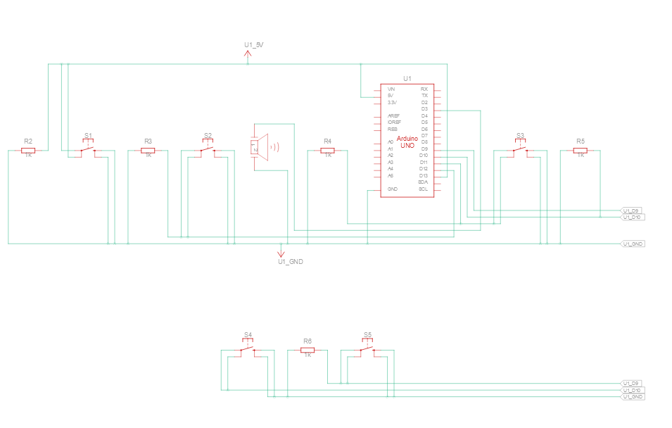
Electronic :
The Piano has two main parts :
- 5x Buttons (Inputs)
- 1x Passive Buzzer (Outputs)
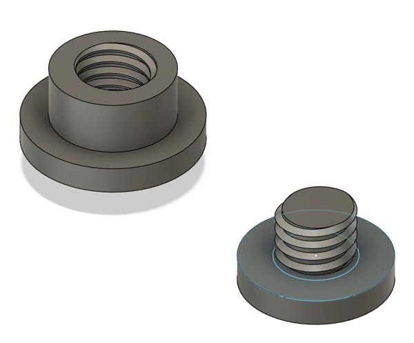
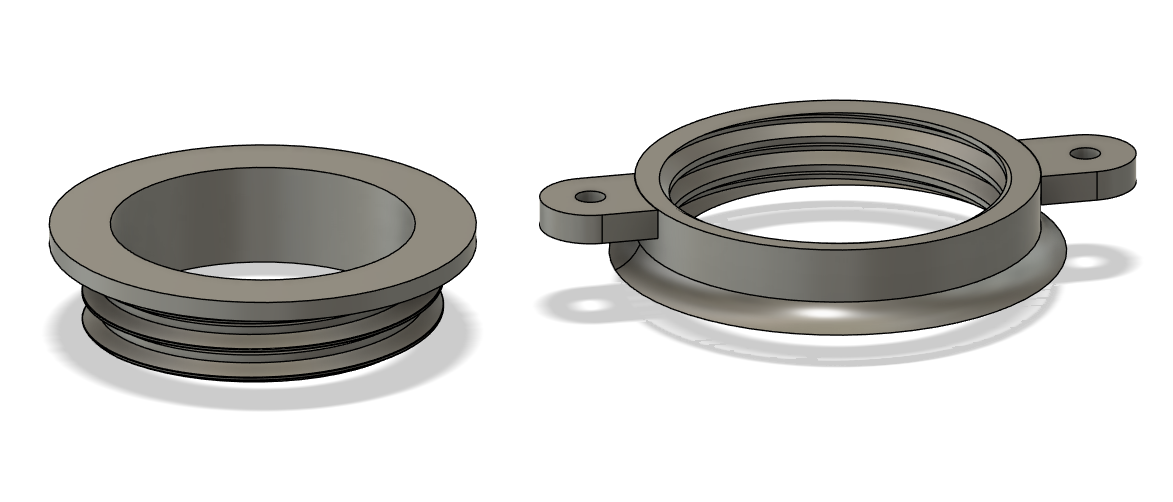
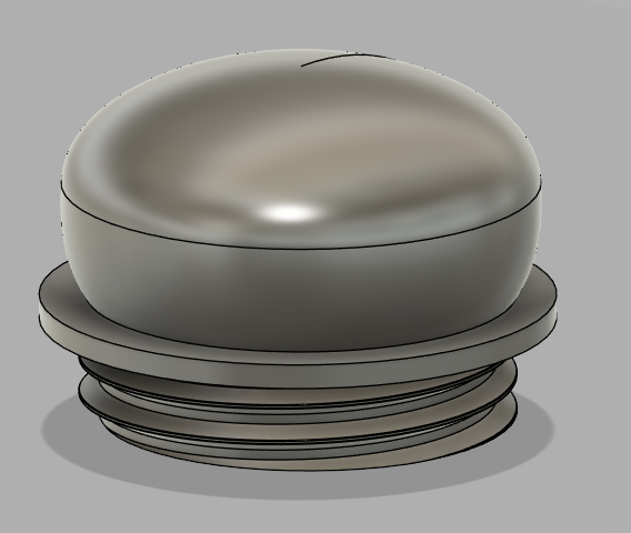
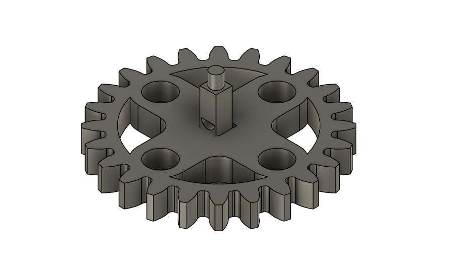
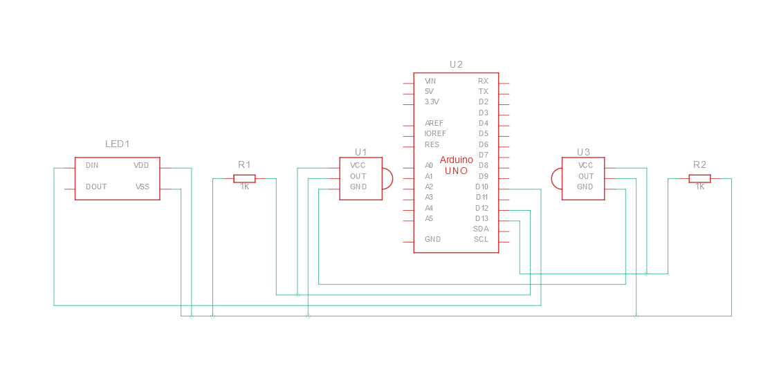
3 wheels
Summary :
allows you to express your visual thoughts by changing each individual values of the color spect. You have the choice for more than 16.7M different colour’s to express your emotions, your mood and much more.
Electronic :
The wheels three main parts :
- 4x Hall effect sensors (inputs)
- 1x Lever button (input)
- 1x LED RGB strip (output)
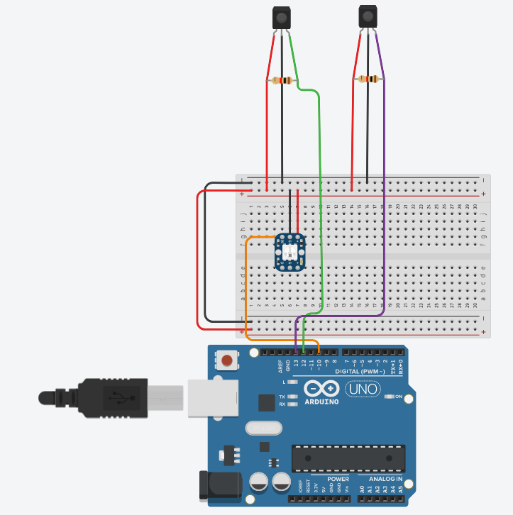
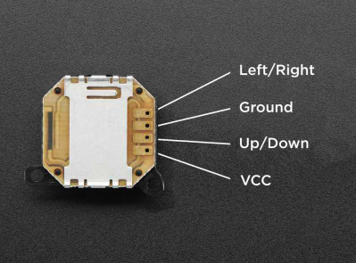
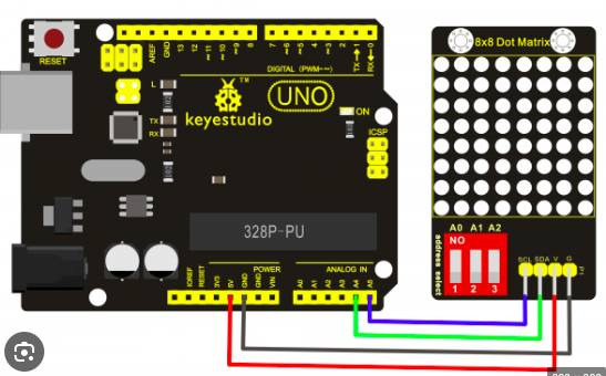
The Snake game
Summary :
-Snake is one of the most known Game is one that exists, so we decided to bring you the game on board our custom fidget toy.
Electronic :
The wheels two main parts :
- 1x Joystick (inputs)
- 1x 8x8Matrix LED screen (output)
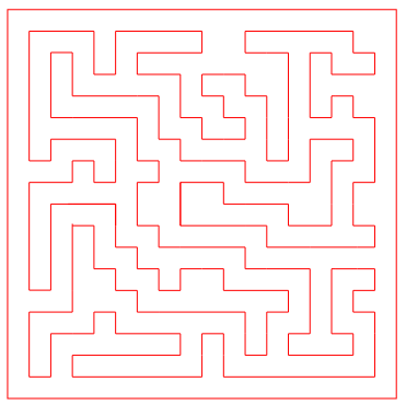
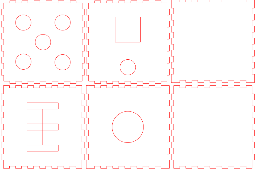
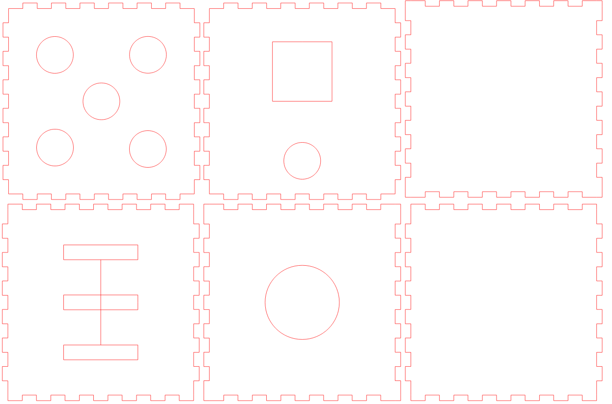
Modules
Summary : Modular and customisable (low tech)
This part consists for you to engage your creativity and create your own little game, that allows you express your sense of creativity and imagination.
3 different Modules :
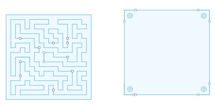
- 1x Maze
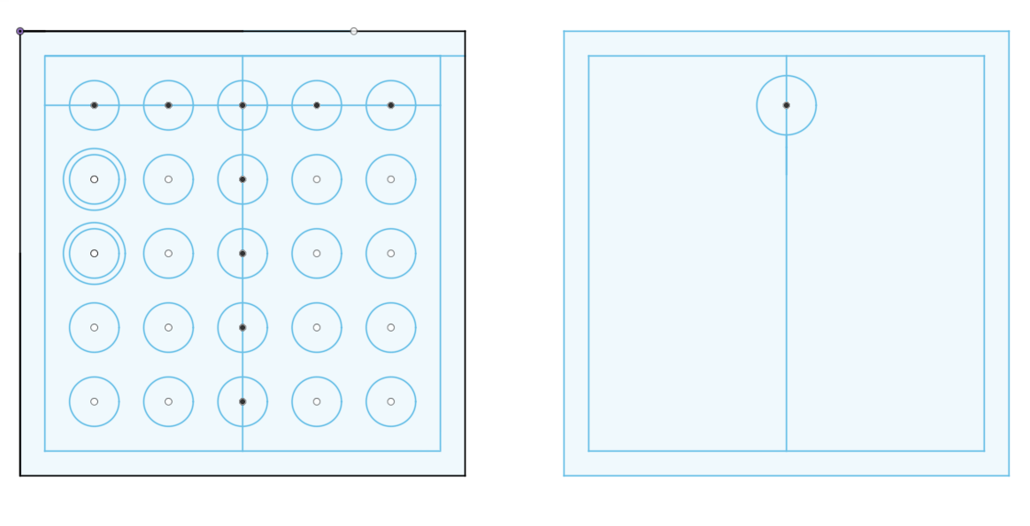
- 1x Power 4
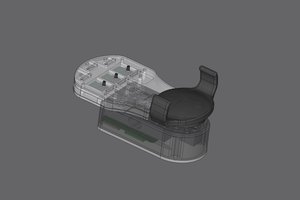
- 1x bottle game
PS : Hope that our school will help some of you to cope with the stress of study and work a little better.


 oneohm
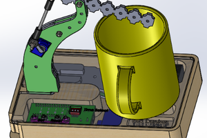
 Nickcasio
 Bruno
Bruno