 Arnov Sharma
3D Design/Concept
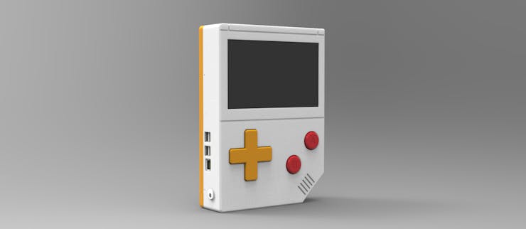
Using images of the original Gameboy, a 3D model of the Gameboy XL had to be designed for this project. The Raspberry Pi model and LCD display were first imported, and we then made sketches around them to construct the gameboy's base body, which has a similar layout. Our model only loosely adheres to the original Gameout's design language; it is not entirely accurate.
We had to divide the front body and back lid piece into two halves because the model was quite big.
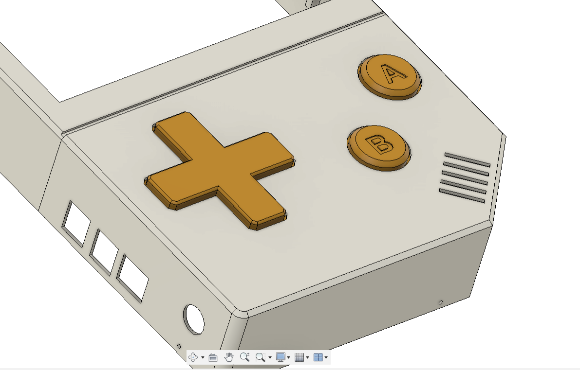
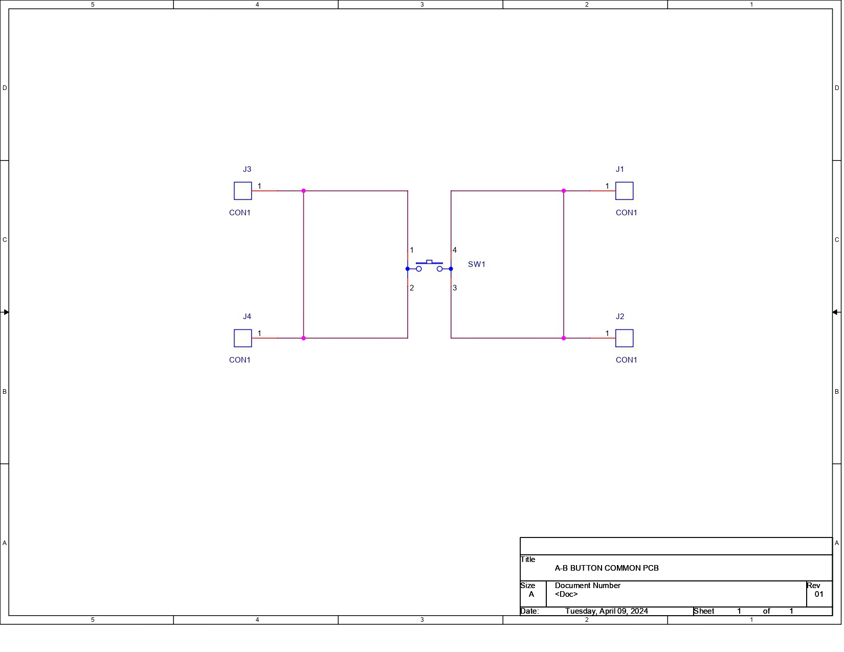
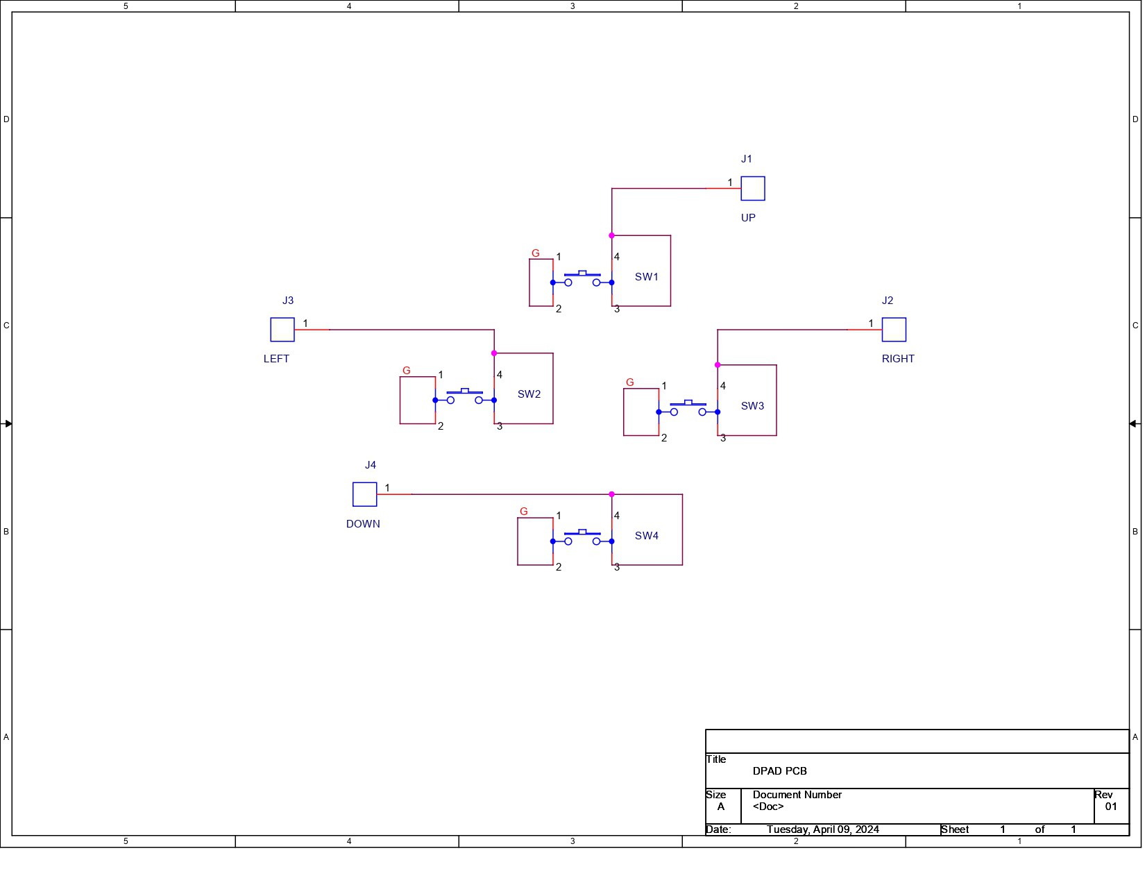
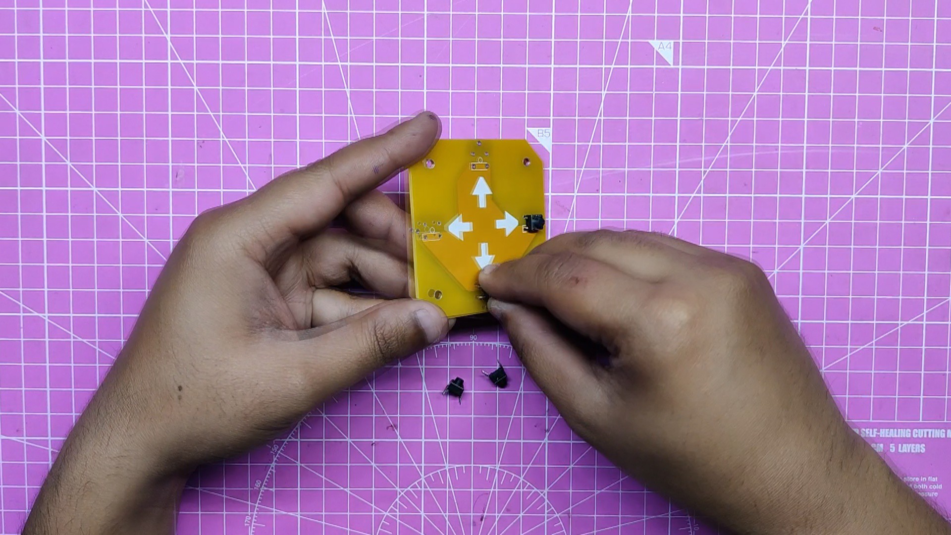
This design also included buttons, and much like the original, we just used A-B and a D pad button.
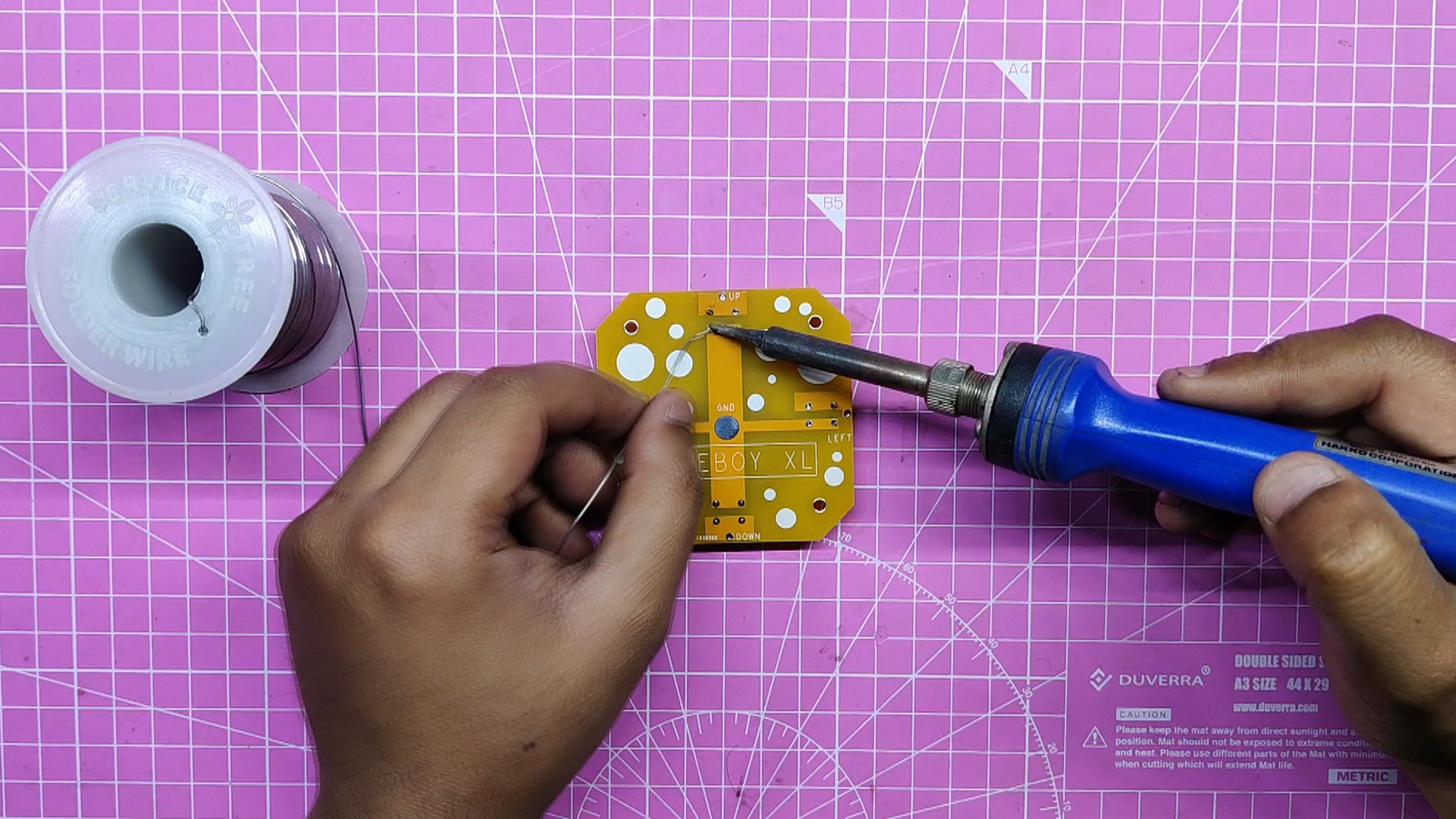
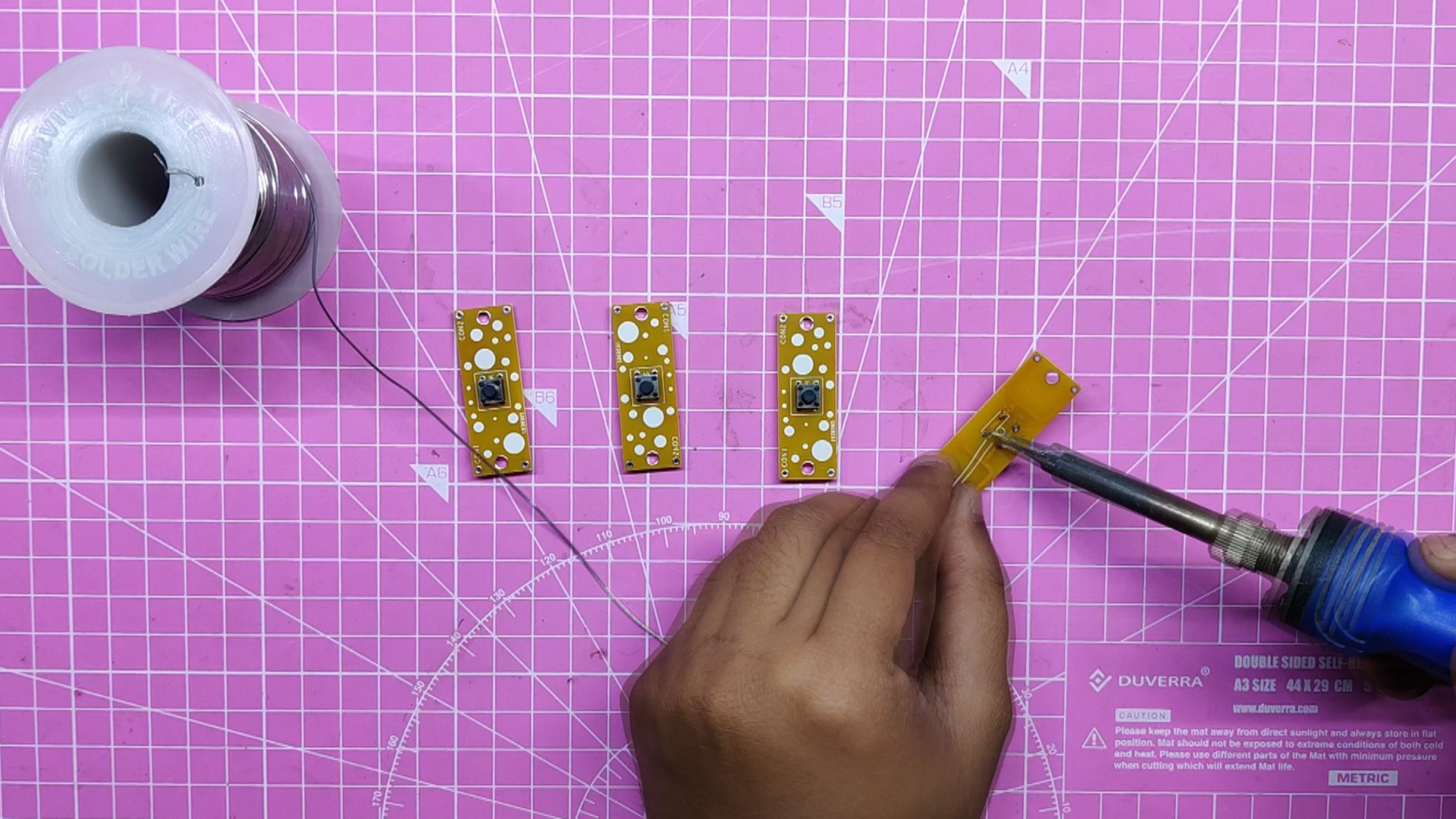
Additionally, we created a PCB with a tactile switch that operates when the button is pressed, allowing the Pi to register the button press. The PCB keeps the button in its place.
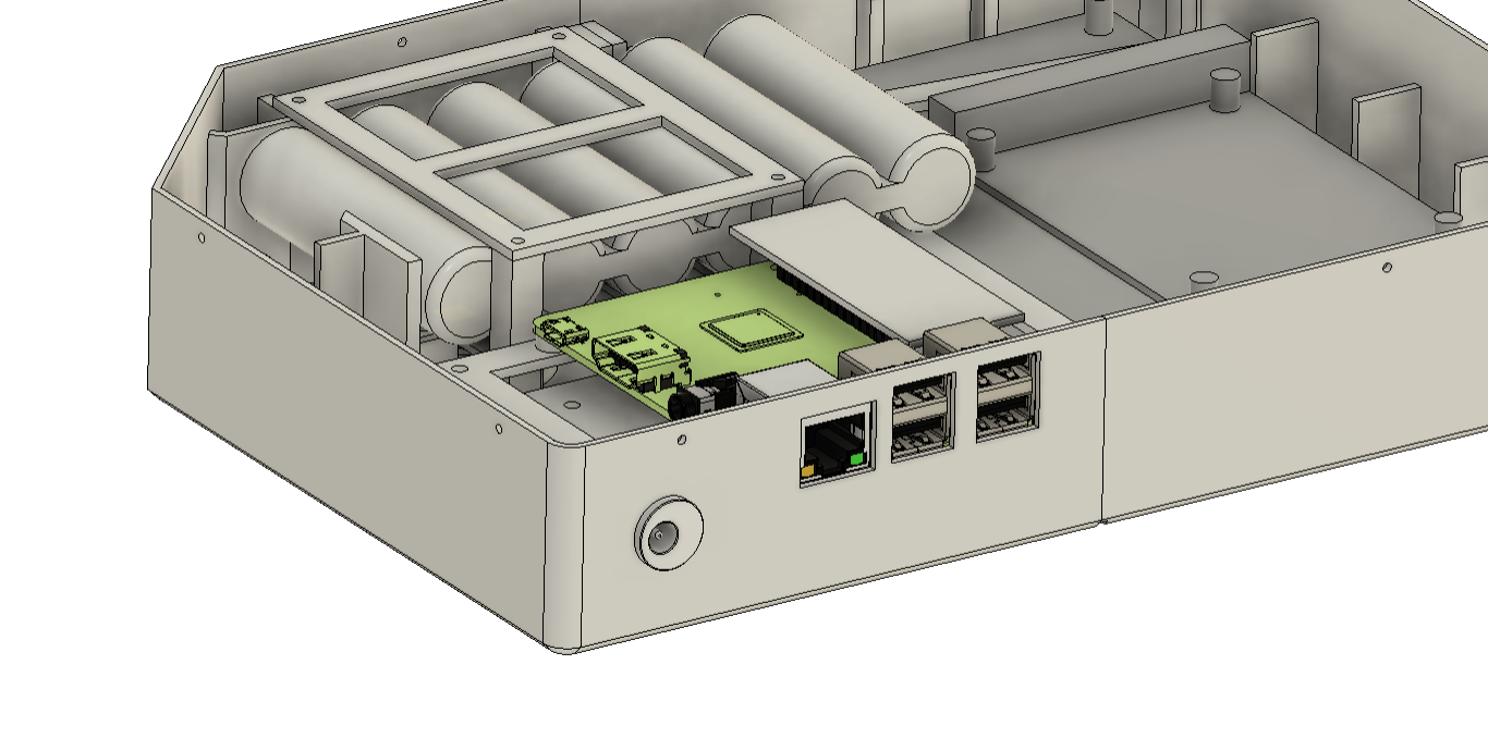
We have modeled a Pi stand that is attached to the body and holds the Pi in place. M2 screws are used to fasten the Pi to the Pi stand.
We created a model of a Pi stand that fastens to the body and supports the Pi. The Pi is attached to the Pi stand using M2 screws.
Because of the ribs we modeled that keep the battery raised, there is a space between the button PCB and the battery. We made a battery retaining clamp that securely fastens the battery pack to the base body in order to keep it in place.
We have created a few ribs on three sides of the display to mount it. This will aid in the assembly process because the display is easy to slide into place and will not wobble or even move.
Additionally, there is a display mount that keeps the display fixed to the body; M2 screws are used to fasten the mount to the body.
On the underside, close to the Pi's USB opening, we have also installed a DC Jack that serves as a battery pack charging socket.
We stole a 3 ohm speaker and an audio module from a previous project, modeled them both, and put them in the lower portion.
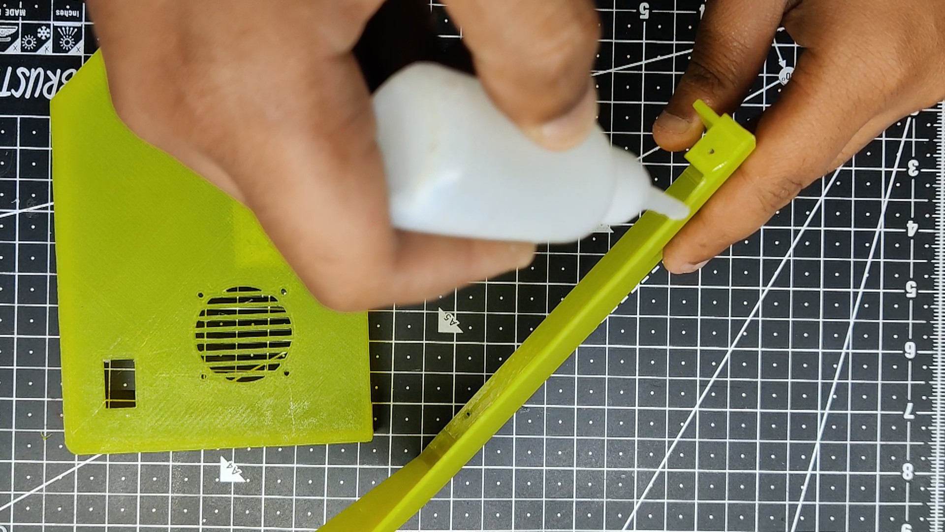
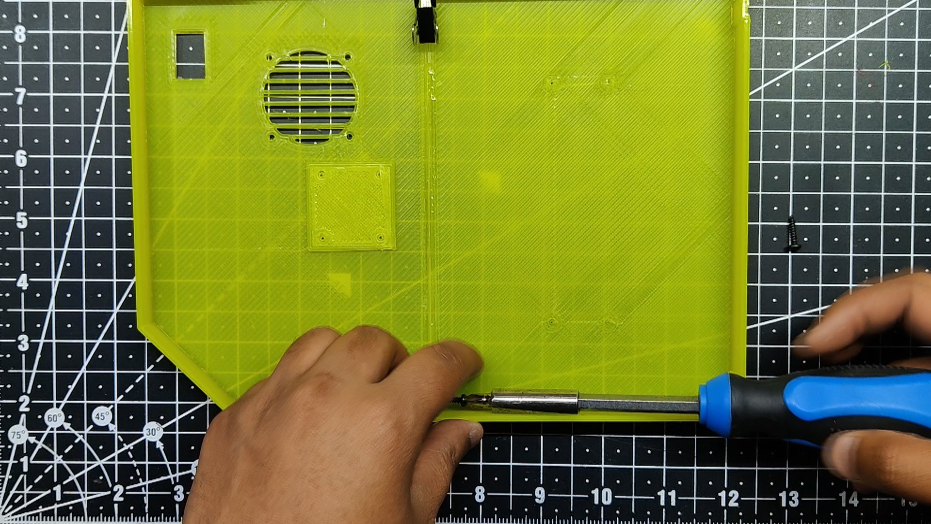
Regarding the back lid part, we have separated it into two halves and included an additional Fan Grill to aid in cooling the Pi.
Additionally, a slot that will be used to mount the rocker switch has been added to the lid part.
The objective of making the XL version of Gameboy was to create a larger version that we could place on our table, attach a wireless or USB controller to, and use to play games.
To do that, we created a model of a stand that allowed us to use the device on a table.
Finally, a nameplate has been placed to the rear side.
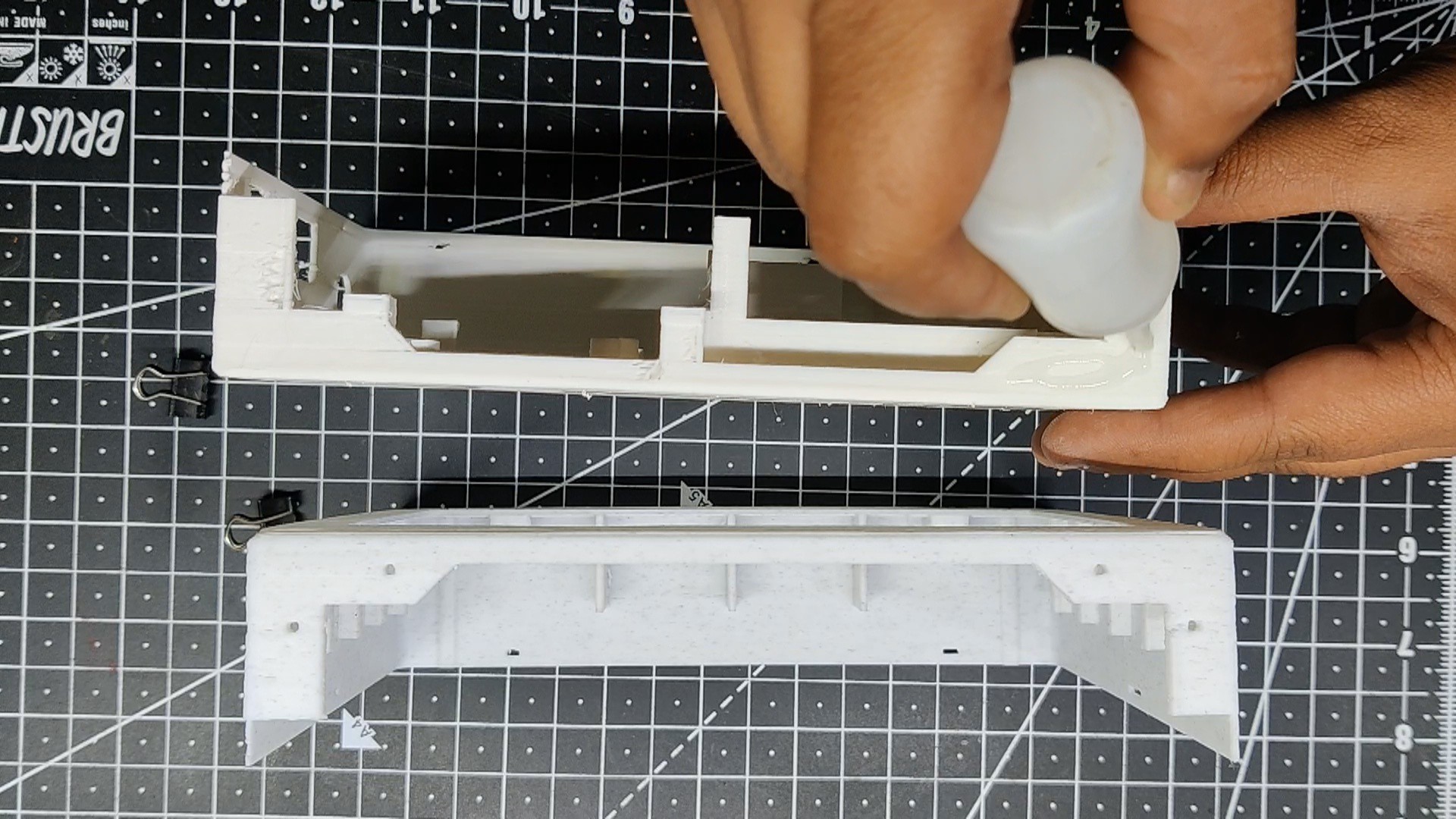
The model was exported into STL files, and each component was then 3D printed. We chose to utilize marble PLA for the main body, orange PLA for the switches, and transparent yellow for the lid and holders.
Raspberry Pi 5- Heart of this project
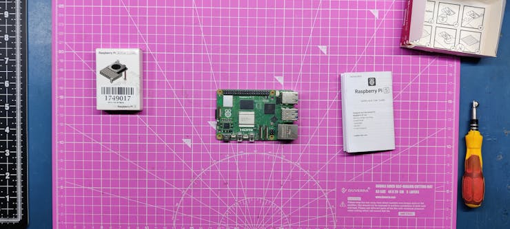
We opted for a little overkill approach for this project, purchasing both the latest 4GB Raspberry Pi 5 and the Original Cooler unit.
We got the Raspberry Pi 5 from Seeed Studio Market.
Regarding the Pi, this emulator project could have been carried out with a Pi4 or a Pi3, but the problem was that neither Pi4 nor Pi3 had the power to run PS1 or PS2 emulator games. Pi4 can run some games for a while before overheating, but Pi3 was underpowered, and I had created a few emulators with it. Therefore, the best course of action was to test out the new Pi5, and I have to say that it ran everything we threw at it.
Though there was a problem with the emulator we were using, we have not tried the PS2 games yet. We want to do so later on, and to make Pi even quicker, we are going to add an NVME SSD.
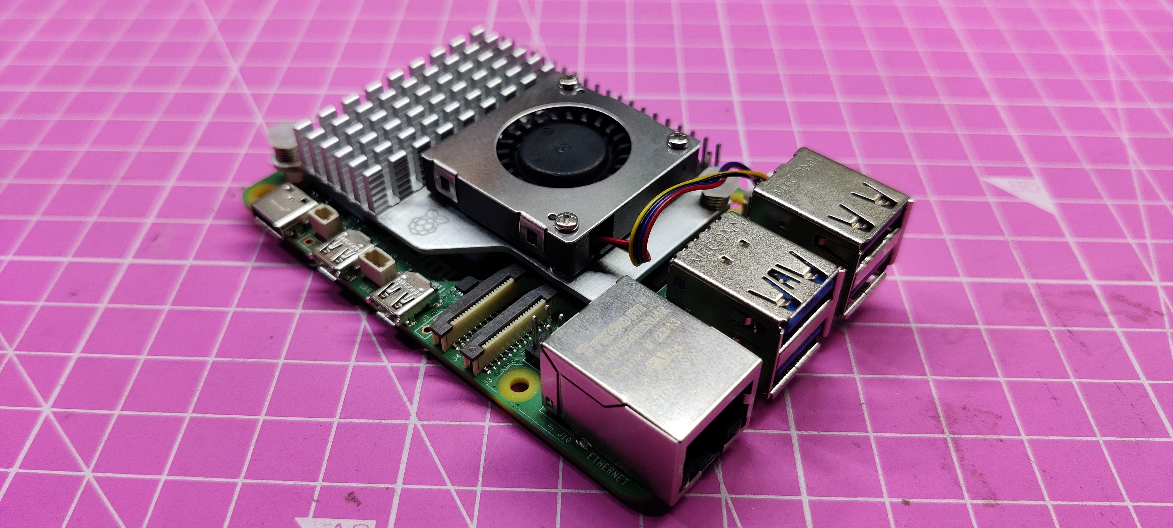
Adding the Cooler with the Pi5
After placing the cooler in the correct order and removing the thermal paste cover, we connected it to the Pi. Two plastic snap latches on the cooler were a really great idea for mounting heatsinks.
After that, we linked the JST connector on the cooler to the JST connector on the Pi5, and the system was prepared for some retro gaming.
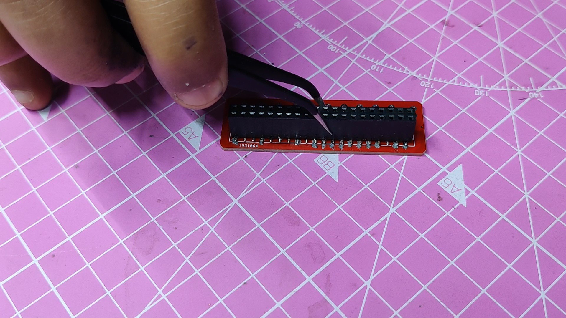
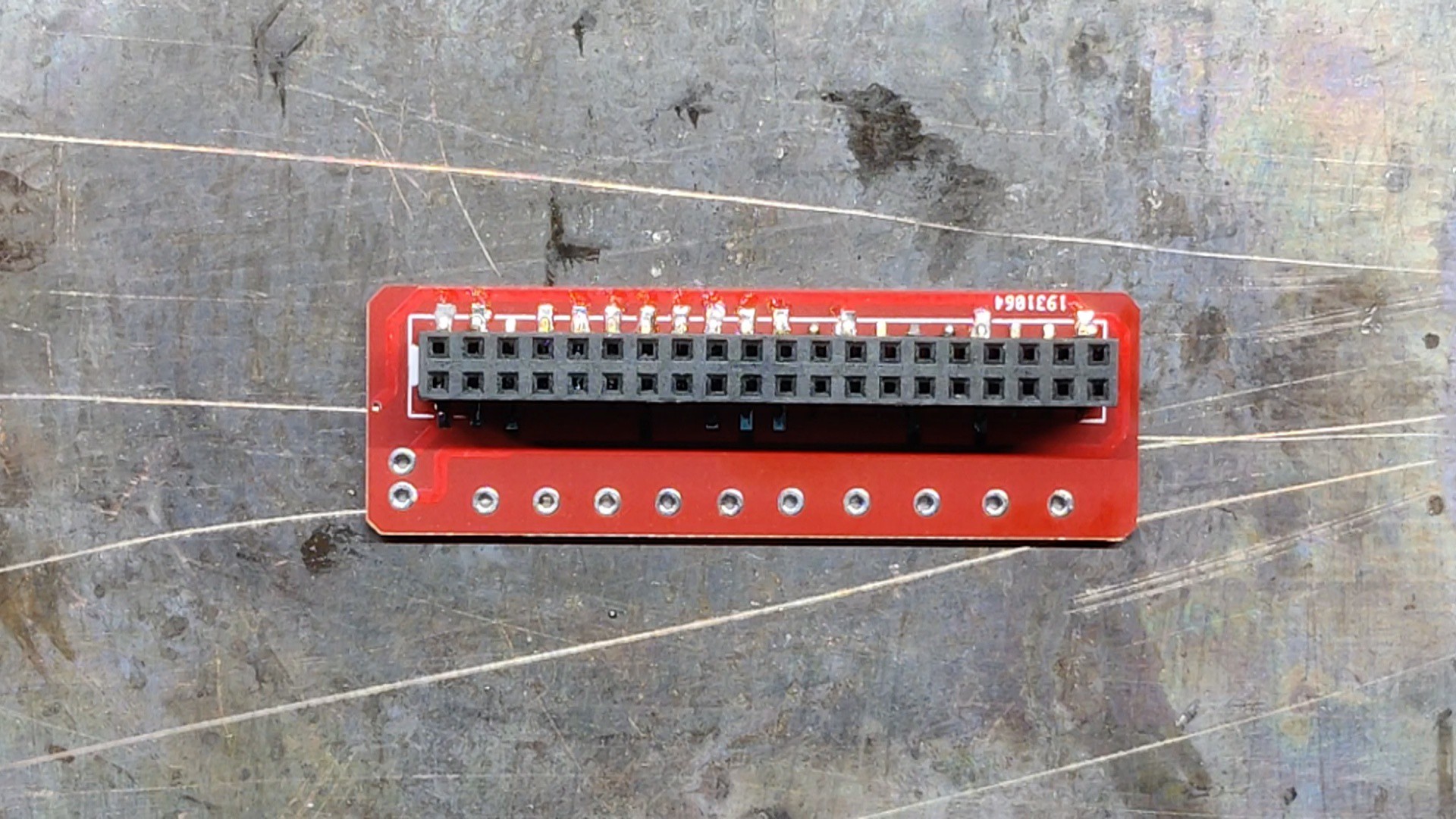
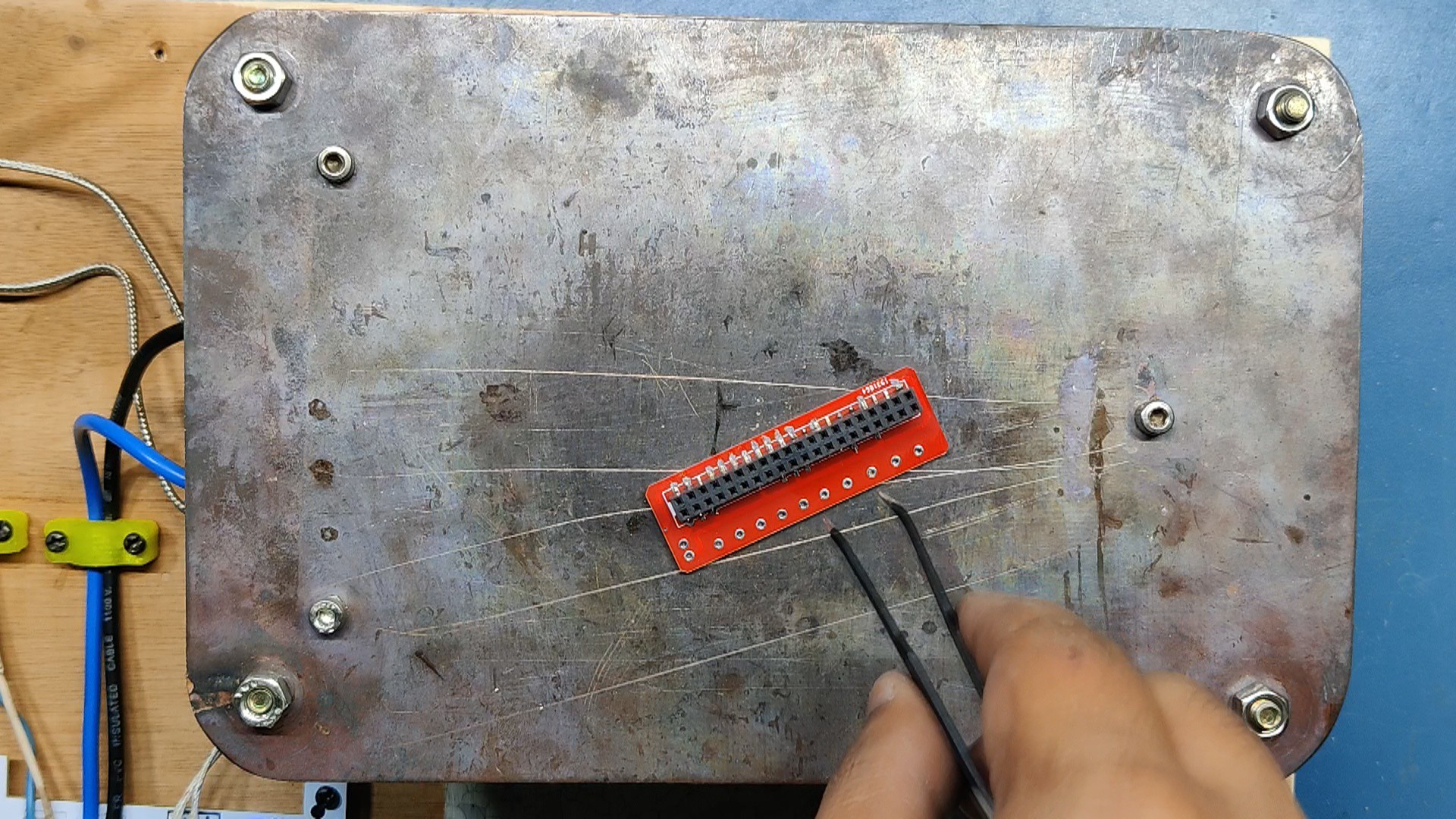
PCB Design
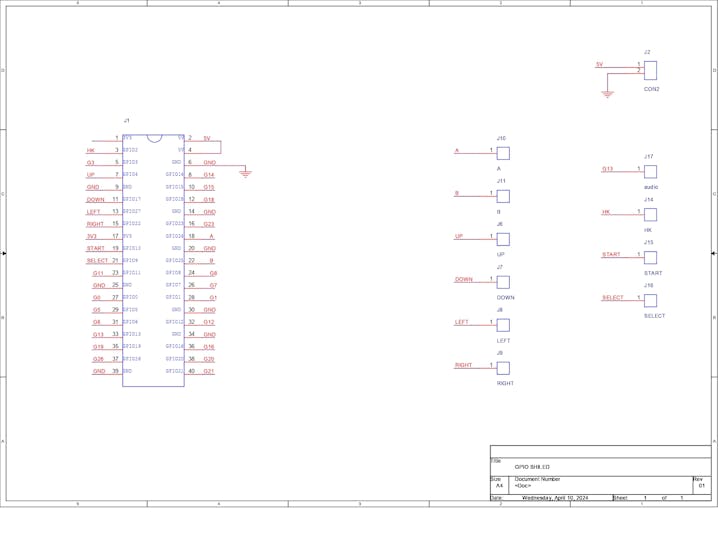
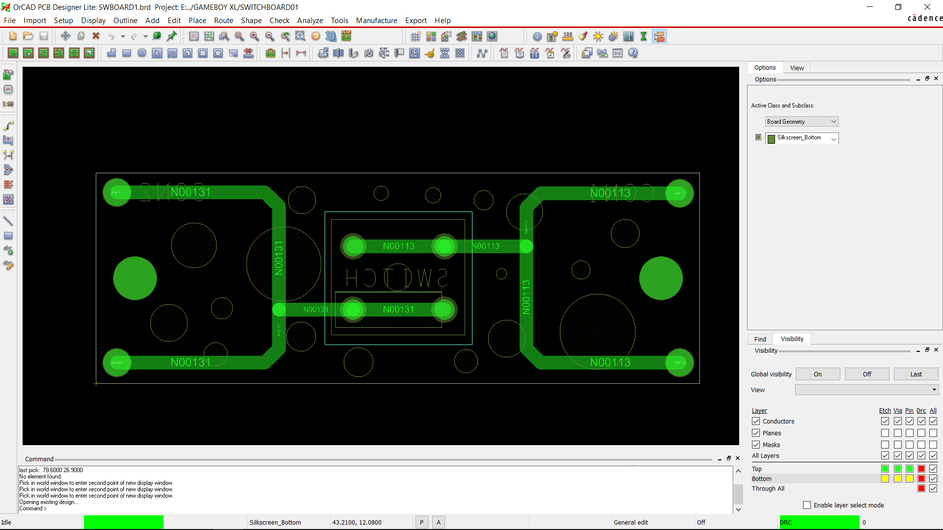
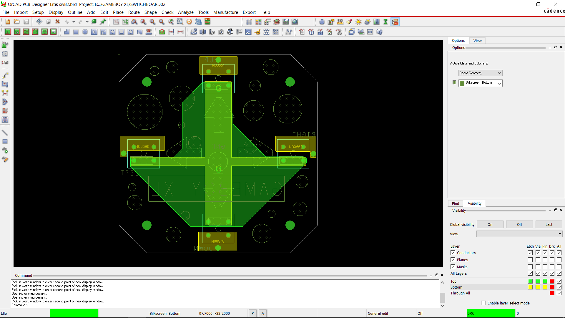
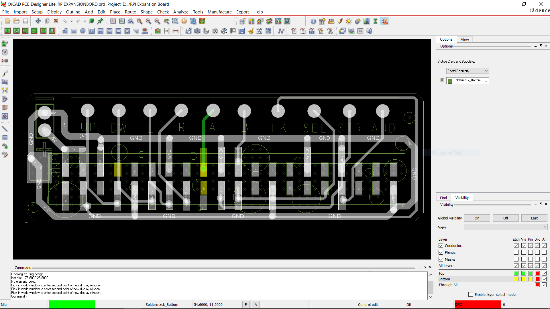
Just a few button boards and one GPIO shield...
Read more »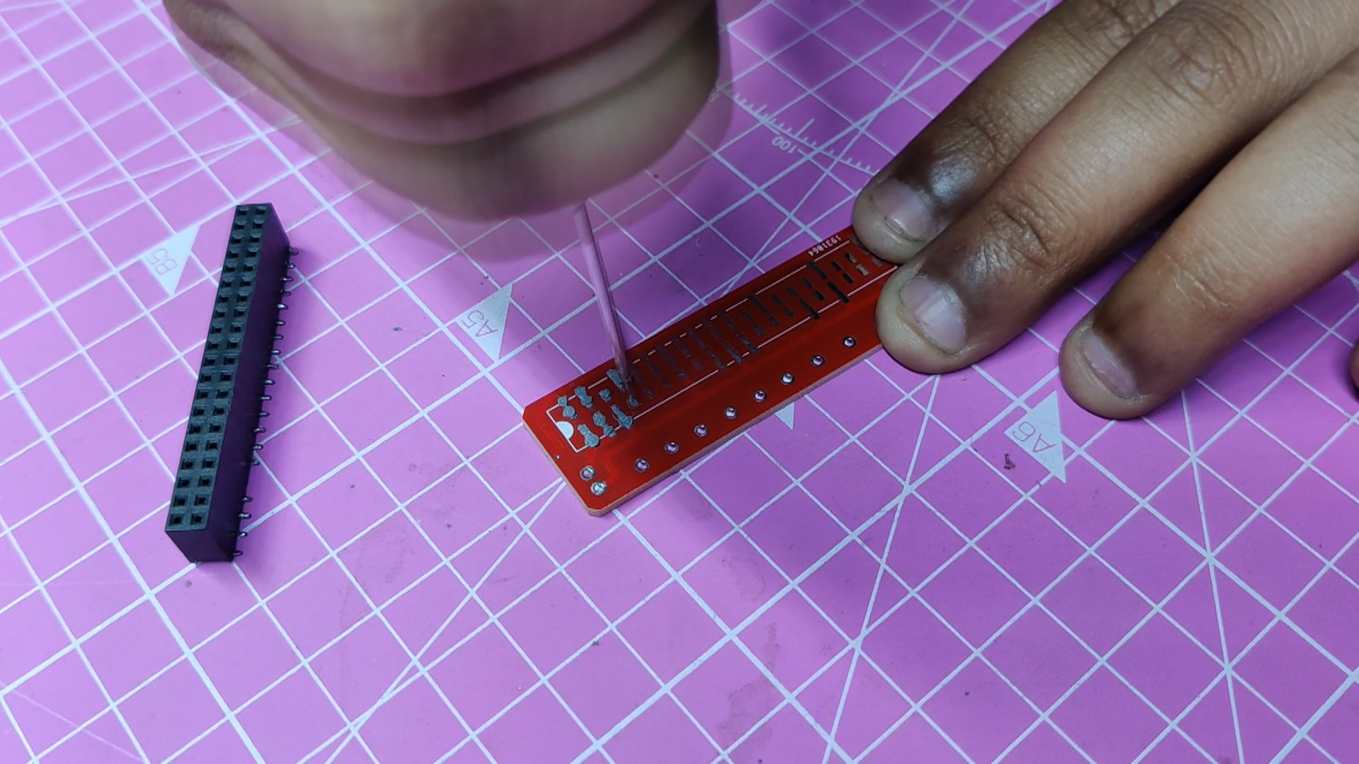
 Maksim Surguy
 production
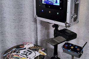
 Kirschner Christoph
 furrysalamander