You need:
- H801 WiFi module
- ESP8266 ESP-01 CH340G programmer (e.g. https://www.amazon.de/-/en/ESP8266-Serial-Adapter-Programmer-Arduino/dp/B07FXP4Y75)
- 5 jumper wires
- Disconnect the power connectors and unbox the PCB.
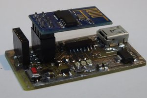
- Connect the 3.3V, TX, RX, and GND between the module (J1) and the programmer, as shown. The sketch shows the orientation of the pins on the programmer connector and the signals are labeled as on the PCB.
- Connect both pads on J3 to enable the programming mode.
- Connect the programmer to the USB port.
- Use the Chrome / edge browser and the online installation tool https://tasmota.github.io/install/.
- After successful programming, disconnect the USB power, remove the J3 wire, and repower the module.
- Now that the Tasmota firmware boots, you can connect to the WiFi hotspot to configure the controller, integrate it into your WiFi, and check that it works. Under configuration > configuration module, select the model type H801. You could also do that by writing module 20 to the console.
- Disconnect the jumper cables and put the PCB back into the box. The PCB is asymmetric, so it will fit only in one orientation.
- Now you can do the final configuration and smart-home integration for a common Tasmota device
I just put the jumper wires into the PCB and used gravity to tension the cables to get good enough contact. I knew that this was a bit risky as if the connection is lost, the ESP might get bricked, but it worked well. It would be better to solder them.
 Alex
Alex
 Marek
Marek
 matt venn
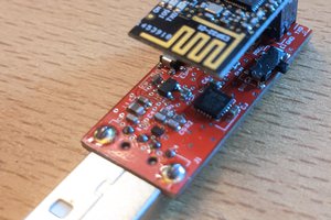
 Thomas Buck