 Silícios Lab
Introduction
Air quality, temperature, humidity and pressure are essential elements to ensure healthy and comfortable indoor environments. However, these parameters are often outside of ideal standards, which can result in a series of health and well-being problems. Air pollution, lack of adequate ventilation, extreme variations in temperature and humidity, as well as fluctuations in atmospheric pressure, are some of the main challenges faced in closed environments.
To monitor and control these factors, the BME680 sensor appears as a versatile and effective solution. This sensor is capable of measuring air quality, detecting substances such as VOCs (volatile organic compounds), in addition to providing accurate data on temperature, humidity and atmospheric pressure in real time.
By integrating the BME680 sensor with the ESP32, it is possible to collect this information continuously and transmit it to an online platform. This allows you to remotely monitor air quality and environmental conditions in real time, enabling corrective measures to be taken when necessary and contributing to the creation of healthier, and more comfortable indoor spaces for everyone.
To monitor this data, we developed an electronic board capable of collecting data from the BME680 sensor with the help of the ESP32.

In this article you will learn:
- Basic operating circuit of the ESP32,
- Battery monitoring circuit,
- Boost circuit for alkaline batteries, and
- Minimum circuit of the BME680 sensor.
Next, we will present the electronic schematic structure of the developed electronic board project.
Do you want to download the electronic files for this project? Click on this link and download now!
Electronic Schematic of the Project
The electronic circuit of the printed circuit board is divided into 5 electronic blocks. All of them are presented in the figure below.

One of the crucial points in any electronic project is the circuit power supply. Our electronic project was developed to use 2 alkaline batteries to power the circuit. However, the voltage of each cell is 1.5V, providing a total of 3V.

In order to guarantee a 3.3V supply for the ESP8266, we developed a boost circuit to increase the voltage to 3.3V and power the project. The CHIP responsible for this task is the TLV61046A.

A factor that impacts several devices that are powered by batteries is the time it takes for the batteries to discharge. It is extremely important to carry out correct management and know the time of use and when it is necessary to change batteries so that the device continues to operate safely in the field. To achieve this, we implemented the INA219 sense in the project.
What is the purpose of the INA219 sensor?
The INA219 sensor is a valuable component for monitoring batteries and analyzing current consumption in electronic circuits during field applications. With its ability to measure battery voltage and current flowing through it, the INA219 provides essential data for evaluating system performance and efficiency. By monitoring battery voltage, operators can closely monitor charging and discharging status, ensuring effective energy management.
Furthermore, by analyzing the current consumption of the circuit, it is possible to identify usage patterns, detect anomalies and optimize energy consumption. This information is crucial for extending battery life, preventing system failures, and improving energy efficiency in field applications, from portable devices to remote monitoring systems. Below we have the INA219 sensor circuit. It communicates via I2C with the ESP32.

Next, we have the BME680 sensor, which will be responsible for monitoring environmental parameters.
BME680 Sensor Circuit
The BME680 sensor, developed by Bosch Sensortec, is a highly advanced device that combines multiple functionalities on a single chip. It is capable of measuring temperature, relative humidity, atmospheric pressure and air quality, making it an...
Read more »
 Alex
Alex
 frederik.deswaef
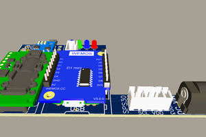
 electronicsworkshops
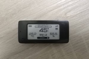
 Andrew Lamchenko