 Georg
GeorgPCB
(I designed the PCB using KI CAD)
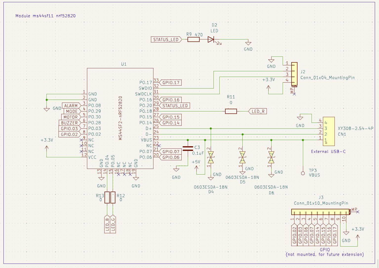
This is the micro controller I am using. It is a SoC of the nrf52820 by MinewSemi. A Chinese chip Module manufacturing company.
To the MC I connected many GPIO pins to mounting pins (bottom right). The pins are not mounted and just for future extension of the boards functionality.
Then there is also SWD programming pin found on pins 32 and 31. Pins 23, 24 and 25 have a USB connection for charging. There are no plans to use it for interfacing.
The alarm is triggered by a button and the mode is set by a switch.
There is also a status LED for debugging on the top.
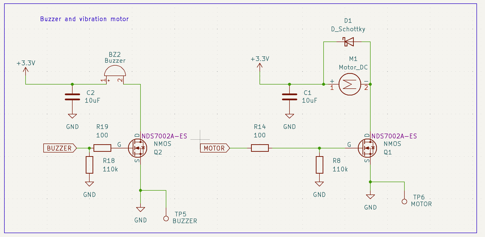
A N-MOS transistor is used to turn on and off the buzzer and motor. These components could draw a lot of current. I don't want to deal with that through the module. There is also a Schottky diode across the motor. This is because motors can act as generators when they are shutting down. This diode protects the system from reverse voltage.
The device is powered by a 18650 Li-Ion cell. I use a MCP73871T-2CCI_ML SoC as a BMS. It shares the load while charging and prevents over- or undercharging. I use a TPS63001 by Texas Instruments to regulate the cell voltage, but it had problems. Maybe because of the layout, but one prototype worked, so I don't know what caused it. All components work with variable voltage so I just bypassed the component on some prototypes.
Case
I designed the case in Fusion360. It is a very good cad program with a free license for hobbyists and students. I am both so it was a perfect match.
The case is not very special. It is printed out of orange PLA and the lid is made out of black TPU. TPU is a flexible thermoplastic which helps to waterproof everything and offers a way to press the button that is on the middle of the pcb.
Software
Everything was written using the nordic connect SDK which is based on
 hesam.moshiri
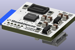
 Matias N.
 ElectroBoy