 Tykhon
So I had the idea for this project for a whole of 3 days, and you know how sometimes you just... get an itch to do the thing... Well, yesterday I did the thing.
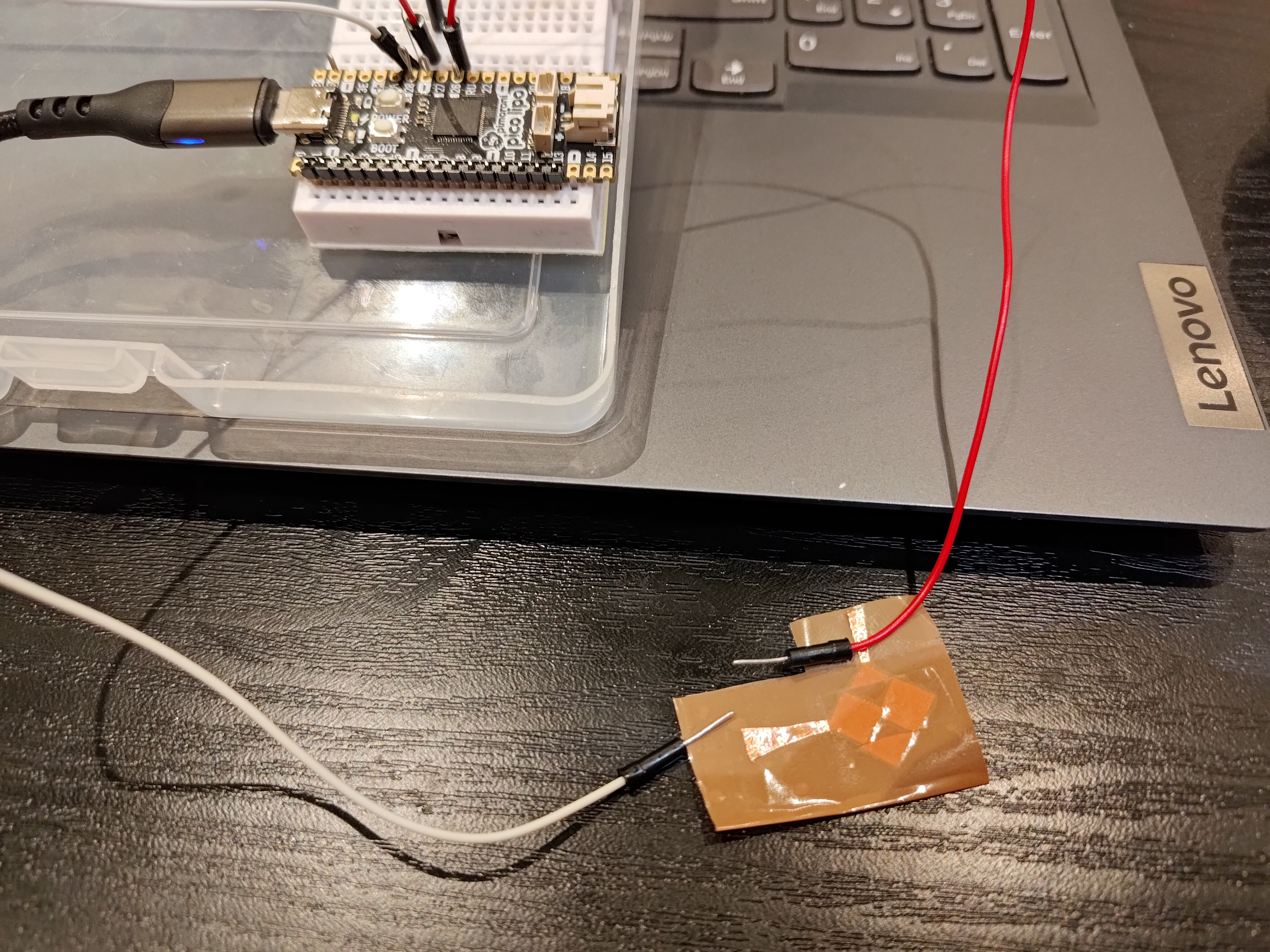
The thing was - run a single-cell button off my Pi Pico (okay, fine, it's Pimoroni's Pico Lipo - but it's pin-compatible so it still counts! And it still has the shitty ADC). I did that, and managed to see a swing of 0.8V - 1.6V between notouch-touch. nice.
Basically, this proves the concept - you CAN swing a line at 10MHz, 25% duty PWM (dear lord whomever made RP2040/'s IO deserves a medal, "PWM on any and all pins? Go for it, we gotchu."), then feed it into ADC, and read back measurable difference between the sensor being touched or not touched.
Before we go any further, my basic-bitch code:
#include <stdio.h>
#include "pico/stdlib.h"
#include "hardware/gpio.h"
#include "hardware/pwm.h"
#include "hardware/adc.h"

int main() {
    // Set CPU frequency to 100MHz
    set_sys_clock_khz( 100000, true );

    // PWM setup on pin 26
    gpio_init( 26 );
    gpio_set_function( 26, GPIO_FUNC_PWM );
    uint slice_num = pwm_gpio_to_slice_num( 26 );

        // Set up PWM clock & wrapping
        // To achieve 10MHz frequency we divide main clock by 10; but then multiply by 4 so our 4 counts complete a cycle.
        // "wrap" is inclusive; "chan_level" is at which count we flip the value
    pwm_set_clkdiv( slice_num, 10.0/4.0 );
    pwm_set_wrap( slice_num, 3 );
    pwm_set_chan_level( slice_num, PWM_CHAN_A, 1 );
    pwm_set_enabled( slice_num, true );

    // ADC setup
    adc_init();
    adc_gpio_init( 28 );
    adc_select_input( 2 );

    stdio_init_all();
    // Keep the program running
    while( 1 ) {
        const float conversion_factor = 3.3f /(1 << 12);
        uint16_t result = adc_read();
        printf( "v: %f V\n", result * conversion_factor );
        sleep_ms( 100 );
    }

    return 0;
}
Clock is dropped to 100MHz to make PWM divider math easier (also, this is a live example of how you can configure your PWM frequency on Pi Pico/RP2040, free of charge!), and other than that there's really nothing to it - pump the TX line, read off RX line. EZ.
I dunno how much physical time adc_read() takes up, so there's still that unknown (I'll need to find that out so the math can be mathin' for matrix scanning), but we're primed and ready to take it to the next level - scanning a matrix. And for that we'll need a PCB, which should also help with all the uncertainties of my ghetto setup where I'm hand-holding leads to raw-dogged sticky copper foil chopped by multitool scissors :D
Ta!
Discussions
Become a Hackaday.io Member
Create an account to leave a comment. Already have an account? Log In.