Close
0%
0%

AI-based Aquatic Ultrasonic Imaging & Water Test

Identify noxious air bubbles lurking in the substrate w/ ultrasonic scans and assess water pollution based on chemical tests simultaneously.

Similar projects worth following
Even though most of us consider water contamination as a gradual occurrence, especially for thriving landscapes, impending pollution can pervade water bodies instantaneously. In the case of enclosed water bodies such as closed lakes, pernicious contaminants can arise in a week and threaten aquatic environments despite not manifesting any indications. These furtively spreading pollutants can even impinge on the health of terrestrial animals by not only poisoning precious water sources but also withering aquatic plants.

In most cases, conducting only surface-level water quality tests is insufficient to pinpoint the hiding pollutants since contaminants can form in the underwater substrate by the accumulation of the incipient chemical agents. These underwater chemical reactions are commonly instigated by detritus, industrial effluents, and toxic sediment rife in the underwater substrate. After the culmination of the sinking debris, these reactions can engender algal blooms, hypoxia (dead zones), and expanding barren lands[1]. Since the mentioned occurrences are only the result of prolonged water pollution, they lead to the inexorable progress of complex toxic chemical interactions, even with plastic debris[2]. Therefore, the precedence must be given to identifying the underlying conditions of increasing underwater chemical reactions.

Especially in lower substrate levels, before reaching hazardous amounts, the combined chemical reactions between pollutants yield ample gas molecules enough to accumulate small-to-moderate air bubbles underwater. These lurking gas pockets affect aquatic plant root systems, deliver noxious contaminants to the surface level, and alter water quality unpredictably due to prevalent emerging contaminants. As a result of the surge of toxic air gaps, the affected water body can undergo sporadic aquatic life declines, starting with invertebrate and fry (or hatchling) deaths. Although not all instances of underwater air bubble activity can be singled out as an imminent toxic pollution risk, they can be utilized as a vital indicator to test water quality to preclude any potential environmental hazards.

In addition to protecting natural enclosed water bodies, detecting the accumulating underwater pollutants can also be beneficial and profitable for commercial aquatic animal breeding or plant harvesting, widely known as aquaculture. Since aquaculture requires the controlled cultivation of aquatic organisms in artificially enclosed water bodies (freshwater or brackish water), such as fish ponds and aquariums, the inflation of underwater air bubbles transferring noxious pollutants to the surface can engender sudden animal deaths, wilting aquatic plants, and devastating financial losses. Especially for fish farming or pisciculture involving more demanding species, the accumulating air bubbles in the underwater substrate can initiate a chain reaction resulting in the loss of all fish acclimatized to the enclosed water body. In severe cases, this can lead to algae-clad artificial environments threatening terrestrial animals and the incessant decline in survival rates.

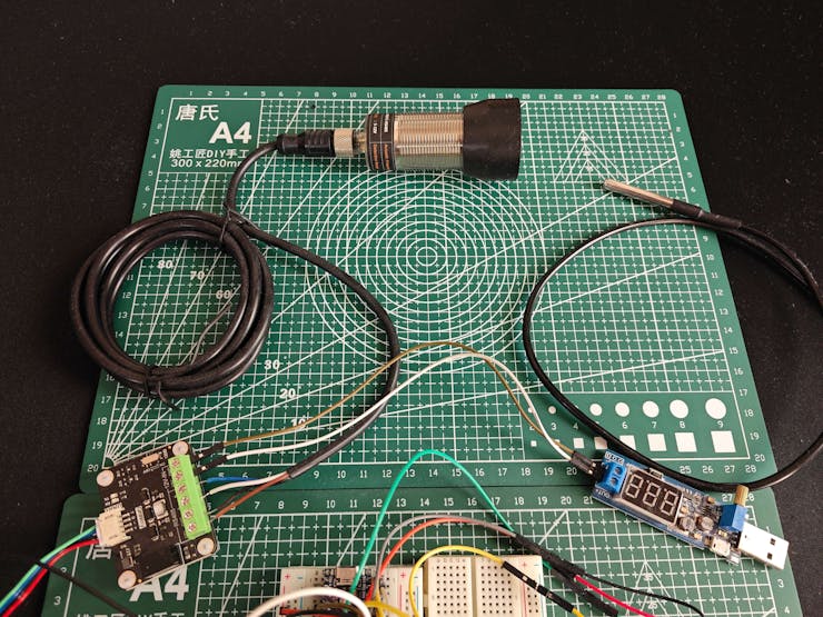
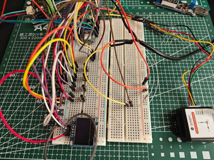
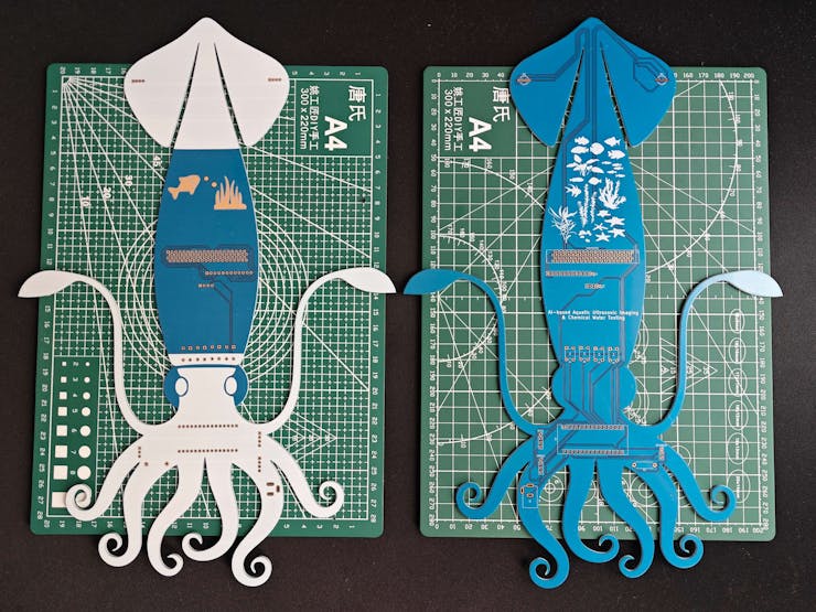
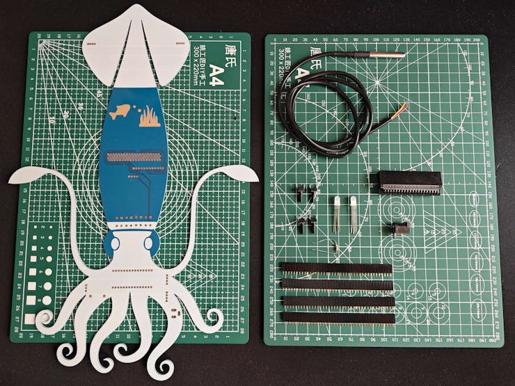
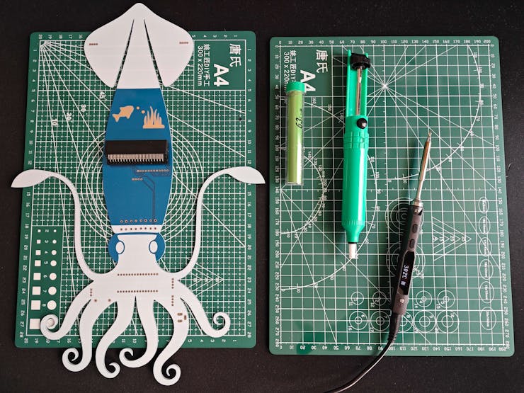
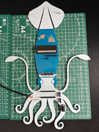
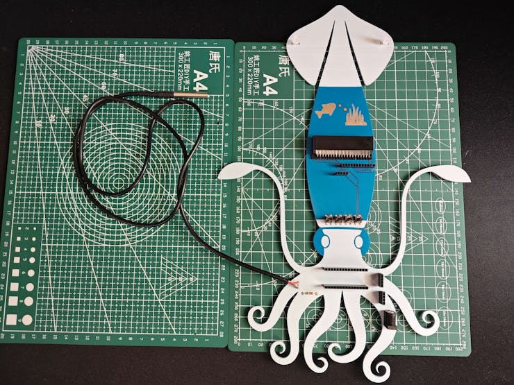
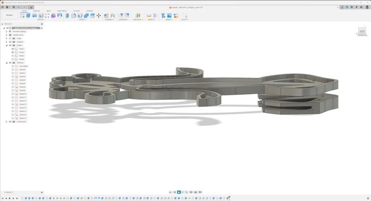
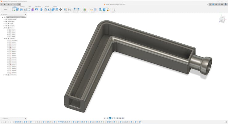
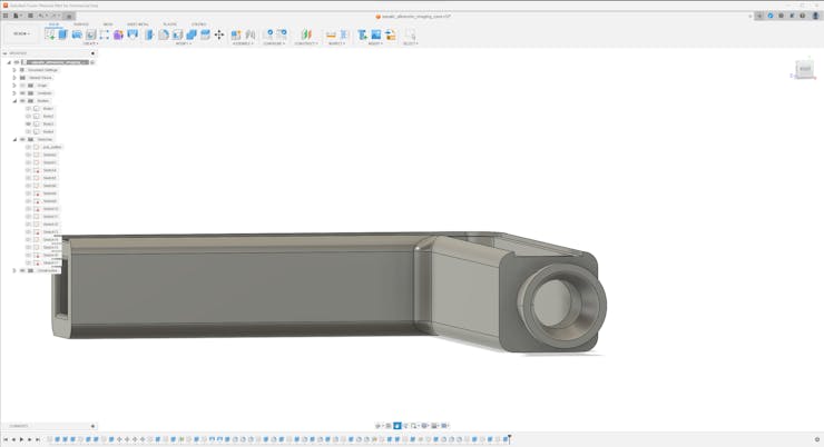
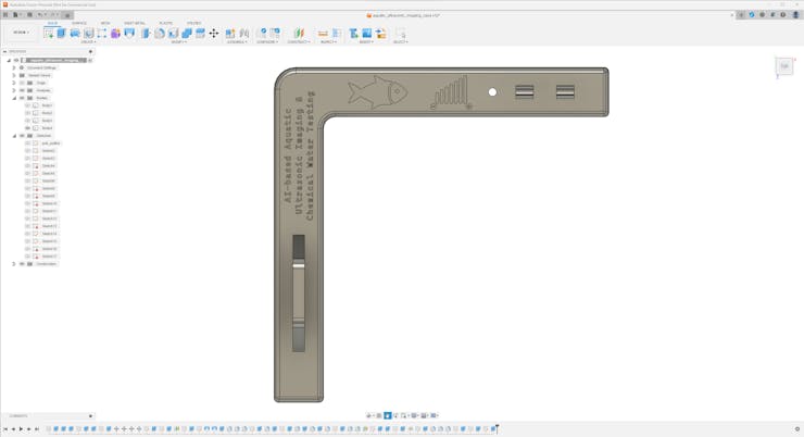
After perusing recent research papers on identifying air bubbles in the underwater substrate, I noticed that there are no practical applications focusing on detecting underwater air bubbles and assessing water pollution consecutively so as to diagnose potential toxic contaminants before instigating detrimental effects on the natural environment or a commercial fish farm. Therefore, I decided to develop a feature-rich AIoT device to identify underwater air bubbles via a neural network model by applying ultrasonic imaging as a nondestructive inspection method and to assess water pollution consecutively based on multiple chemical water quality tests via an object detection model. In addition to AI-powered functions, I also decided to build capable user interfaces and a push notification service via Telegram.

Before working on data collection procedures and model training, I thoroughly searched for a natural or artificial environment demonstrating the ebb and flow of underwater substrate toxicity due to overpopulation and decaying detritus. Nevertheless, I could not find a suitable option near my hometown because of endangered aquatic life, unrelenting habitat destruction, and disposal of chemical waste mostly caused by human-led activities. Thus, I decided to set up an artificial aquatic environment simulating noxious air bubbles in the underwater substrate and potential...

Read more »

  • 1 × ELECROW Custom PCB
  • 1 × UNIHIKER
  • 1 × USB Webcam (PK-910H)
  • 1 × Arduino Nano ESP32
  • 1 × DFRobot URM15 - 75KHZ Ultrasonic Sensor

View all 19 components

  • 1
    Step 1: Designing and soldering the Squid-inspired PCB

    Before prototyping my Squid-inspired PCB design, I inspected the detailed pin reference of Nano ESP32, the micro:bit connector-based UNIHIKER pinout, and the supported transmission protocols of the measurement sensors. Then, I checked the wireless (Wi-Fi) communication quality between Nano ESP32, UNIHIKER, and the web application while transferring and receiving data packets.

    Then, I designed my Squid-inspired PCB by utilizing Autodesk Fusion 360 and KiCad. Since I wanted to design a distinctive 3D-printed hang-on holder to simplify the PCB placement on the simulated fish farm (aquarium), I created the PCB outline on Fusion 360 and then imported the outline file (DXF) to KiCad. As mentioned earlier, I decided to utilize squid as the fulcrum of my PCB design since I wanted my device to resemble the enchanting underwater atmosphere.

    To replicate this air bubble and water pollution detection device, you can download the Gerber file below and order my PCB design from ELECROW directly.

    Normally, it would not be possible to embed most of the commercial single-board computers directly into a PCB without applying arduous disassembly methods. Nevertheless, UNIHIKER provides a micro:bit-compatible connector to access the GPIO interface of the microcontroller coprocessor (RISC-V). Therefore, I was able to embed UNIHIKER as the centerpiece of my PCB by utilizing a micro:bit-compatible edge connector from Kitronik.

    If you want to add the Kitronik edge connector to your PCB designs, you can inspect its KiCad component library and footprint.

    By utilizing a TS100 soldering iron, I attached headers (female), a DS18B20 waterproof temperature sensor, a Kitronik micro:bit-compatible edge connector, pushbuttons (6x6), 5 mm common anode RGB LEDs, a 4.7K resistor, and a power jack to the Squid PCB.

    📌 Component list on the PCB:

    A1 (Headers for Arduino Nano ESP32)

    UNIHIKER1 (Kitronik micro:bit-compatible Edge Connector)

    DS18B20 (DS18B20 Waterproof Temperature Sensor)

    URM15 (Headers for RS485-to-UART Signal Adapter Module)

    ACC1 (Headers for Serial 6-Axis Accelerometer)

    S1 (Headers for SSD1306 OLED Display)

    R1 (4.7K Resistor)

    K1, K2, K3, K4 (6x6 Pushbutton)

    D1, D2 (5 mm Common Anode RGB LED)

    J2 (Headers for Available UNIHIKER Pins)

    J1 (Power Jack)

  • 2
    Step 1.1: Making connections and adjustments
    // Connections
    // Arduino Nano ESP32 :
    //                                URM15 - 75KHZ Ultrasonic Sensor via RS485-to-UART Signal Adapter Module
    // D3      ------------------------ TX
    // D2      ------------------------ RX
    // 3.3V    ------------------------ +
    // GND     ------------------------ -
    //                                Serial 6-Axis Accelerometer
    // 3.3V    ------------------------ VCC
    // D5      ------------------------ RXD
    // D4      ------------------------ TXD
    // GND     ------------------------ GND
    //                                DS18B20 Waterproof Temperature Sensor
    // A1      ------------------------ Data
    //                                SSD1306 OLED Display (128x64)
    // A4      ------------------------ SDA
    // A5      ------------------------ SCL
    //                                Control Button (A)
    // D6      ------------------------ +
    //                                Control Button (B)
    // D7      ------------------------ +
    //                                Control Button (C)
    // D8      ------------------------ +
    //                                Control Button (D)
    // D9      ------------------------ +
    //                                5mm Common Anode RGB LED
    // D10     ------------------------ R
    // D11     ------------------------ G
    // D12     ------------------------ B
    &
    &
    &
    // Connections
    // UNIHIKER :
    //                                5mm Common Anode RGB LED
    // P4      ------------------------ R
    // P5      ------------------------ G
    // P6      ------------------------ B

    #️⃣ Although the URM15 is an exceptional ultrasonic ranging sensor providing an IP65 waterproof probe with a measuring range of 30 cm - 500 cm, it does not support direct data transmission and requires the standard Modbus-RTU protocol for stable communication. Thus, I utilized an RS485-to-UART signal adapter module (active-isolated) to obtain the generated ultrasonic distance measurements from the ultrasonic sensor and transfer them to Nano ESP32 via serial communication. Since Nano ESP32 cannot supply the stable 12V required for the URM15 ultrasonic sensor, I connected a USB buck-boost converter board to an external battery to obtain the demanding 12V to power the ultrasonic sensor through the signal adapter module.

    #️⃣ Since the URM15 ultrasonic sensor supports the external temperature compensation to obviate the undulating ambient temperature effect, I utilized a DS18B20 waterproof temperature sensor to tune the ultrasonic sensor. As shown in the schematic below, before connecting the DS18B20 waterproof temperature sensor to Nano ESP32, I attached a 4.7K resistor as a pull-up from the DATA line to the VCC line of the sensor to generate accurate temperature measurements.

    #️⃣ To detect the movement of the ultrasonic sensor probe underwater while collecting data, I utilized a 6-axis accelerometer supporting UART communication. Since I employed Nano ESP32 to pass the collected data buffers directly to the web application, I did not need to connect an external storage module such as a microSD card module.

    #️⃣ To provide the user with a feature-rich interface, I connected an SSD1306 OLED display and four control buttons to Nano ESP32. I also added an RGB LED to inform the user of the device status while performing operations related to Nano ESP32.

    #️⃣ Since UNIHIKER (RK3308 Arm 64-bit) is an outstandingly compact single-board computer providing a USB Type-A connector for peripherals, I was able to connect a high-quality USB webcam (PK-910H) to capture and save image samples effortlessly.

    #️⃣ As explained earlier, UNIHIKER comes with a micro:bit-compatible connector to access the GPIO interface of the microcontroller coprocessor (RISC-V). I utilized the Kitronik edge connector to access the GPIO pins and adjust the secondary RGB LED to inform the user of the device status while performing operations related to UNIHIKER. In this regard, I was able to embed UNIHIKER into the Squid PCB as the centerpiece to build a single-unit device.

    #️⃣ Before embedding UNIHIKER, I tested the micro:bit-compatible GPIO interface by utilizing a soldered Kitronik breakout board with the edge connector.

    #️⃣ After completing soldering and adjustments, I attached all remaining components to the Squid PCB via the female headers.

  • 3
    Step 2: Designing and printing the Aquatic-themed case

    Since I focused on building a feature-rich and accessible AI-powered device that identifies noxious underwater air bubbles via aquatic ultrasonic scans and evaluates water pollution based on chemical water quality tests via object detection so as to inform the user via Telegram push notifications, I decided to design a robust and modular case allowing the user to hang the Squid PCB on the aquarium, place the high-quality USB webcam when standing idle, and position the ultrasonic sensor effortlessly while scanning underwater substrate. To avoid overexposure to water and prevent open wire connections from short circuits, I added a removable top cover mountable to the main case via snap-fit joints. The semicircular-shaped mounting brackets on the top cover let the user attach the DS18B20 waterproof temperature sensor effortlessly. Then, I designed a unique PCB holder encasing the Squid PCB outline and a hang-on aquarium connector mountable to the PCB holder via M3 screws and nuts. To place the high-quality USB webcam when standing idle, I also designed a hang-on camera holder attachable to the side of the aquarium. Furthermore, I decided to emboss aquatic life with sound-based graphic icons on the removable top cover and the camera symbol on the camera holder to highlight the qualifications of this AI-powered underwater air bubble detection device.

    Since I needed to position the URM15 ultrasonic sensor accurately while scanning the underwater substrate and generating data buffers, I added a special cylindrical slot to the end point of the L-shaped main case in order to fasten the ultrasonic sensor seamlessly.

    I designed the L-shaped main case, the removable top cover, the Squid PCB holder, the hang-on aquarium connector of the PCB holder, and the hang-on camera holder in Autodesk Fusion 360. You can download their STL files below.

    Then, I sliced all 3D models (STL files) in Ultimaker Cura.

    Since I wanted to create a mystique watery structure for the device case and apply a unique underwater theme representing the mesmerizing aquatic life, I utilized these PLA filaments:

    • ePLA-Silk Magic Green-Blue (main case and top cover)
    • ePLA-Matte Light Blue (PCB holder and hang-on connectors)

    Finally, I printed all parts (models) with my brand-new Anycubic Kobra 2 Max 3D Printer.

    Since Anycubic Kobra 2 Max is budget-friendly and specifically designed for high-speed printing with a gigantic build volume, I highly recommend Anycubic Kobra 2 Max if you are a maker or hobbyist needing to print large prints without compartmentalizing your design and losing structural integrity while working on multiple prototypes before finalizing a complex project.

    Thanks to its upgraded direct extruder and vibration compensation features, Anycubic Kobra 2 Max provides 300 mm/s recommended print speed (up to 500 mm/s) and enhanced layer quality. Also, it provides a high-speed optimized cooling system, reducing visible layer lines and complementing the fast printing experience. Since the Z-axis has dual-motors and dual-support rods, it prevents vibration from affecting layer smoothness and integrity, even at higher print speeds.

    Furthermore, Anycubic Kobra 2 Max provides a magnetic suction platform on the heated bed for the scratch-resistant PEI spring steel build plate, allowing the user to remove prints without any struggle, even for larger prints up to 420x420x500 mm. Most importantly, you can level the bed automatically via its user-friendly LeviQ 2.0 automatic leveling system and custom Z-axis compensation. Also, it has a smart filament runout sensor and supports Anycubic APP for remote control and management.

    #️⃣ First of all, remove all fixing plates. Then, install the gantry frame and support rods.

    #️⃣ Install the print head and adjust the X-axis belt tensioner. Then, install the touchscreen and the filament runout sensor.

    #️⃣ Connect the stepper, switch, screen, and print head cables. Then, attach the filament tube and use cable ties to secure the cables properly.

    #️⃣ If the print head or bed is shaking, adjust the hexagonal isolation columns underneath them.

    #️⃣ To avoid software-related print failures, update the device firmware manually via USB or directly over Wi-Fi.

    I encountered some errors due to Cura configurations before the official 2.3.6 firmware.

    #️⃣ After the firmware upgrade, go to Settings ➡ More Settings ➡ Guide so as to initiate the LeviQ 2.0 automatic bed leveling system and configure vibration calibration.

    #️⃣ Finally, fix the filament tube with the cable clips, install the filament holder, and insert the filament into the extruder.

    #️⃣ Since Anycubic Kobra 2 Max is not officially supported by Cura yet, we need to set it manually. Fortunately, Anycubic provides detailed configuration steps for Anycubic Kobra 2 Max on Cura.

    #️⃣ First of all, create a custom printer profile on Cura for Anycubic Kobra 2 Max with given printer settings.

    #️⃣ Then, import the printer profile (configuration) file provided by Anycubic, depending on the filament type.

View all 33 instructions

Enjoy this project?

Share

Discussions

kutluhan_aktar wrote 05/06/2024 at 19:37 point

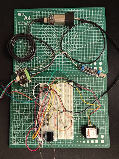
Please feel free to leave a comment here if you have any questions or concerns regarding this project 🙂

  Are you sure? yes | no

Similar Projects

Does this project spark your interest?

Become a member to follow this project and never miss any updates