 Gabriel Cséfalvay
[Cover illustration based on icons by Freepik and Natthapong on Flaticon.]
Basic IO port configuration
EBI port   IO port name   Function
 3            PORTF        address bus (15:8)
 2            PORTK        address bus (7:0)
 1            PORTJ        data bus
 0            PORTH        control signals, address bus (21:16)
(Pinout: see XMEGA AU Manual > EBI > I/O Pin and Pin-out Configuration > SRAM 4PORT NOALE)
Note: In the A1s the EBI doesn't have the PORT3, so you cannot use them in NOALE mode. Only A1Us have the PORT3.
I used this very basic configuration for this project.
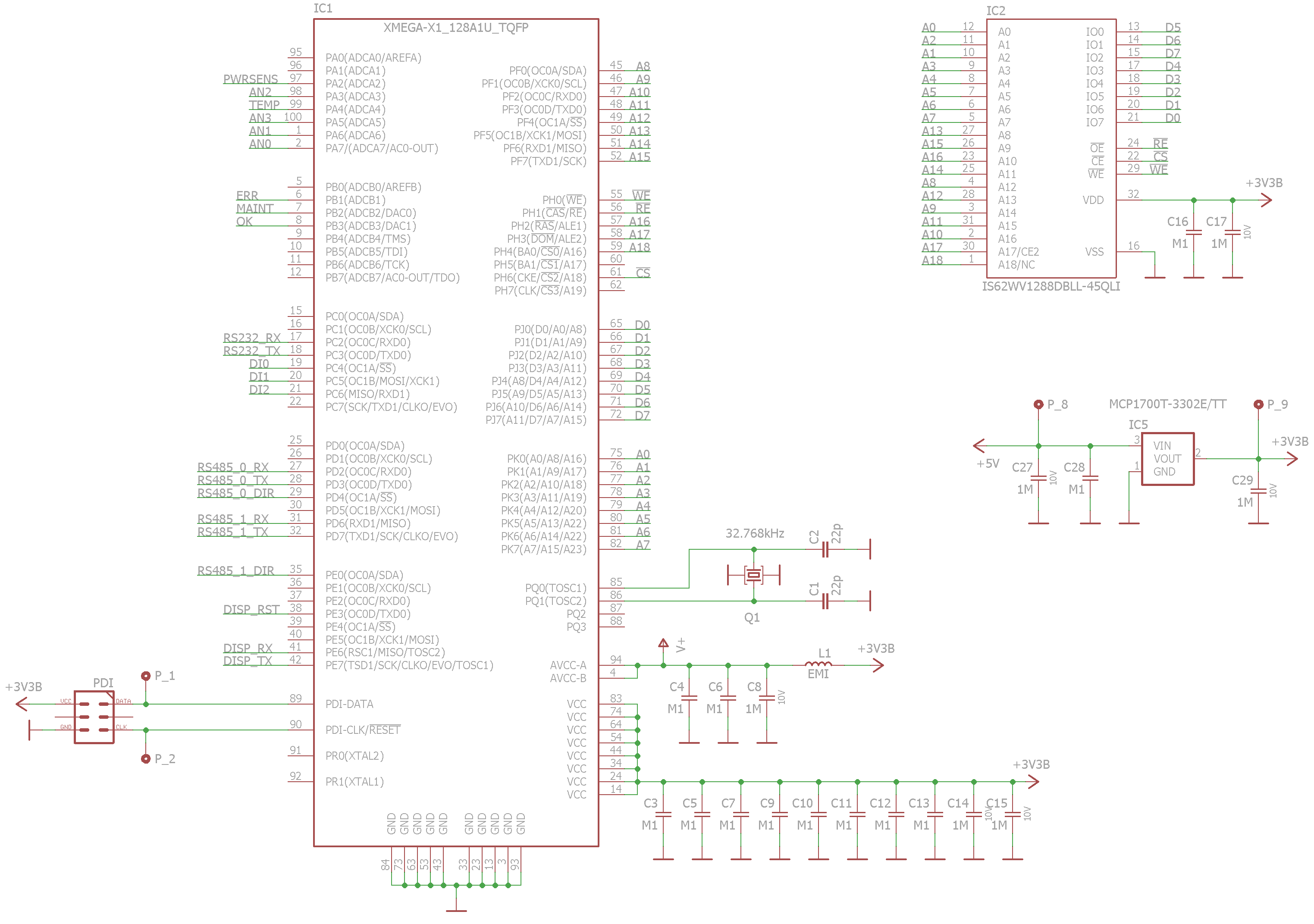
Schematic
How to use external RAM in C
The compiler can automatically and seamlessly place variables in the external RAM if it immediately follows the internal RAM. But: watch the stack. The stack is by default placed at the end of the internal RAM. Further reading on memory sections and stack: http://www.nongnu.org/avr-libc/user-manual/malloc.html
Init code example
void external_ram_init(void) __attribute__ ((naked, used, section (".init1")));
void external_ram_init(void)
{
  // clear r1
  // Needed because this is in the .init1 section

  asm volatile ("clr  __zero_reg__   \n\t");

  // set IO pins

  PORTF.DIR = 0xFF;  // EBI A15-A8
  PORTK.DIR = 0xFF;  // EBI A7-A0
  PORTH.DIR = 0xFF;  // EBI A18-16, CS, RE, WE
  PORTH.OUT = _BV(0) | _BV(1) | _BV(6) | _BV(3);   // EBI: RE, WE, CS: active low signals (idle is high), CS2: active high (not used but connected -> activate)

  // set EBI port configuration

  PORTCFG.EBIOUT = PORTCFG_EBIADROUT_PF_gc | PORTCFG_EBICSOUT_PH_gc;
  EBI.CTRL = EBI_SRMODE_NOALE_gc | EBI_IFMODE_4PORT_gc;

  // set the chip select 2 for the SRAM

  // Note: I didn't want to use the CS3 because if it's used alone (no other CSs) then no CS signal is emitted. See
  // see XMEGA AU Manual > EBI > Chip Select as Address Line. I needed the CS signal because the SRAM chip had lower
  // current consumption with inactive CS (idle mode).

  EBI.CS2.BASEADDR = 0x0000;
  EBI.CS2.CTRLB = EBI_CS_SRWS_1CLK_gc; // 62,5ns R/W cycle @ 32MHz - you have to meet the SRAM speed specification (see the SRAM datasheet)
  EBI.CS2.CTRLA = EBI_CS_ASPACE_128KB_gc | EBI_CS_MODE_SRAM_gc;
}
Here the external RAM is placed to the range 0x0000 - 0x1FFFF. The IO registers and the internal RAM have priority over EBI, so effectively only the 0x4000-0x1FFFF range is used here.
You need to put this code in .init1 because .init2 initializes the stack. If your stack is in the internal RAM, you can put this to the .init3 (the .data and .bss sections are initialized in the .init4 section) (http://www.nongnu.org/avr-libc/user-manual/mem_sections.html). Also the r1 register is initialized in .init2, so in .init1 it is a good idea (I think) to clear it manually.
Atmel Studio hack for ext. RAM debuggings
Open c:\Program Files (x86)\Atmel\Studio\7.0\packs\atmel\XMEGAA_DFP\1.0.36\atdf\ATxmega128A1U.atdf
Add the EXTERNAL_RAM line like this:
<address-space name="data" id="data" start="0x0000" size="0x1000000" endianness="little">
    <memory-segment start="0x0000" size="0x001000" type="io" rw="RW" exec="0" name="IO"/>
    <memory-segment start="0x1000" size="0x000800" type="eeprom" rw="RW" exec="0" name="MAPPED_EEPROM"/>
    <memory-segment start="0x2000" size="0x002000" type="ram" rw="RW" exec="0" name="INTERNAL_SRAM"/>
    <memory-segment start="0x4000" size="0x00C000" type="ram" rw="RW" exec="0" name="EXTERNAL_RAM"/>
  </address-space>
Restart.
This will show you the range 0x4000 - 0xFFFF (external RAM) in the memory window during debugging, also the variables in the external RAM will be showed correctly when hovering the variable names. You can edit the size if you need.
Unfortunately you can't configure this on a project basis (I think), so you'll have to watch yourself whether the RAM was exhausted. Alternatively you could create separate .atdf files for each project with different RAM sizes/ranges.
How to place variables explicitly in the internal RAM
If you need some data security in your project, you'll probably want to explicitly place sensitive data (e.g. plaintext - unencrypted data) in the internal RAM. (Why would you encrypt data if one can see them on the external memory bus?)
Also if you need quick access to some data (e.g. context switches when using an OS), you'll probably want to place those data (e.g. stacks of threads) in the internal RAM.
a.) Use automatically generated sections. If you place a variable in the .noinit section, it will be on the beginning of the RAM, e.g. probably in the internal RAM. ...of course if you can go along with uninitialized variables.
b.) Create a memory section in the internal RAM with the -Wl,-section-start=sectionname=0xaddress parameter. Move the .data and .bss sections to another place (http://www.nongnu.org/avr-libc/user-manual/mem_sections.html). Note that for the linker, RAM starts at 0x800000 (this is an avr-gcc convention to adapt gcc to harvard architecture processors). In Atmel Studio: Project > Properties > Toolchain > Memory Settings.
This is good for placing variables in a place that is not used by the compiler automatically. But how can one be sure? I personally had issues with this: avr-gcc did not warn me about overlapping of my sections and automatically generated sections (.data, .bss), and happily used the same address for two different variables.
To place variables in a specific section:
#define INTRAM __attribute__ ((section (".noinit")))

uint16_t variable_in_internal_ram INTRAM;
Avr-gcc's limitation for pointers
As of version 4.9, avr-gcc supports only 16-bit RAM pointers. This places a limitation of 64KiB on the practically usable RAM size.
As a workaround you can switch RAM pages (higher address bits) "by hand". This can be useful if you have, let's say, 128KiB RAM and want to place one big 64KiB array in the upper 64KiB of the RAM (it can be of any size). In this case you can write a simple function to access the array. It is less useful if you have many small variables.
C Code example
#define THE_BIG_ARRAY_OFFSET 0x10000UL

uint8_t read_from_the_big_array(uint32_t index)
{
  uint32_t address = THE_BIG_ARRAY_OFFSET + index;
  uint8_t read_data;

  ATOMIC_BLOCK(ATOMIC_RESTORESTATE)
  {
    EIND = address>>16; //TODO EIND??? no, RAMPX+asm needed
    read_data = *(uint8_t*)(uint16_t)address;
    EIND = 0;
  }

  return read_data;
}
Second workaround: use a 32-bit processor.
Notes
EBI port 3 can be moved to PORTE (see PORTCFG.EBIOUT > EBIADROUT bits).
The chip select signals can be moved to ports E, F and L (see PORTCFG.EBIOUT > EBICSOUT bits).
Pins of unused CS signals can be used as address lines in some configs (Tab. 27-4). Does this mean that these address lines move when the CS signals are moved, or do they stay on the original port? Datasheet is not clear about this.
In 4-port no-ALE no-LPC mode, there are address lines assigned to the ALE1 and ALE2 pins (Tab. 27-4). These pins are used for latching in the LPC configuration per se (so they are not address lines). It is a bit confusing as LPC and no-LPC modes can be mixed for different chip selects.
ALE and LPC are modes where several address/data lines are multiplexed together on one IO port:
ALE1:       address bytes 0 and 1,
ALE2:       address bytes 0 and 2,
ALE12:      address bytes 0, 1 and 2
LPC ALE1:   data byte and address byte 0
LPC ALE12:  data byte and address byte 0 and 1
The usage of ALE lines are configured globally for EBI (EBI.CTRL), however, the LPC is enabled individually per Chip Select (EBI.CSn.CTRLA).
Further reading: AVR1312: Using the XMEGA External Bus Interface
_________________
Contact me if you have any suggestions.