 Guido
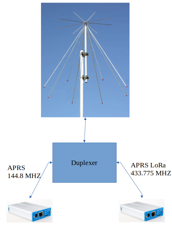
GuidoBlock Diagram
Calculations
The duplexer is obtained putting together two separated filters:
- high pass for 433 MHz
- low pass for 144 MHz
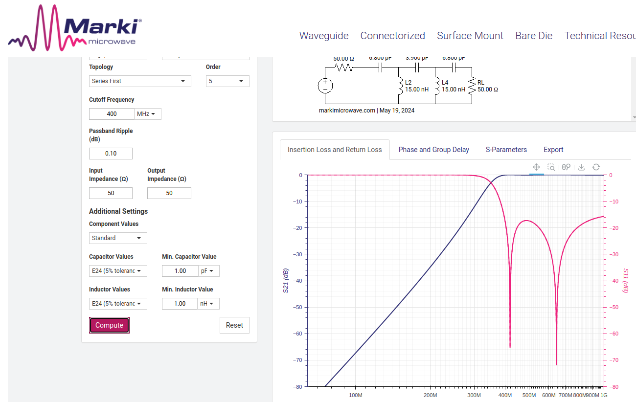
i calculated the two filters separately using lc-filter-design-tool/.
See below the calculation for the 432 MHz high pass filter: note that I set the cutoff frequency at 400 MHz
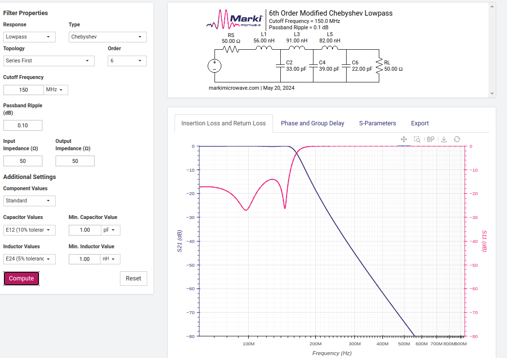
and the 144 MHz low pass filter. Please note I set a 150 MHz cutoff.
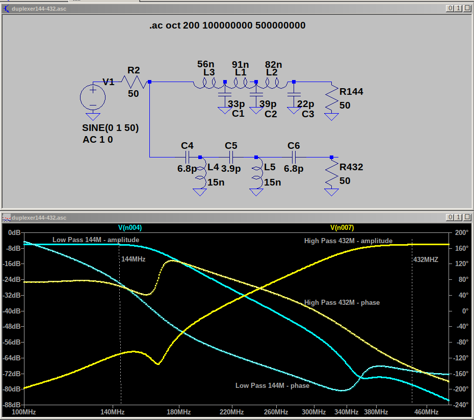
Schematic and LTSpice simulation
Assembly
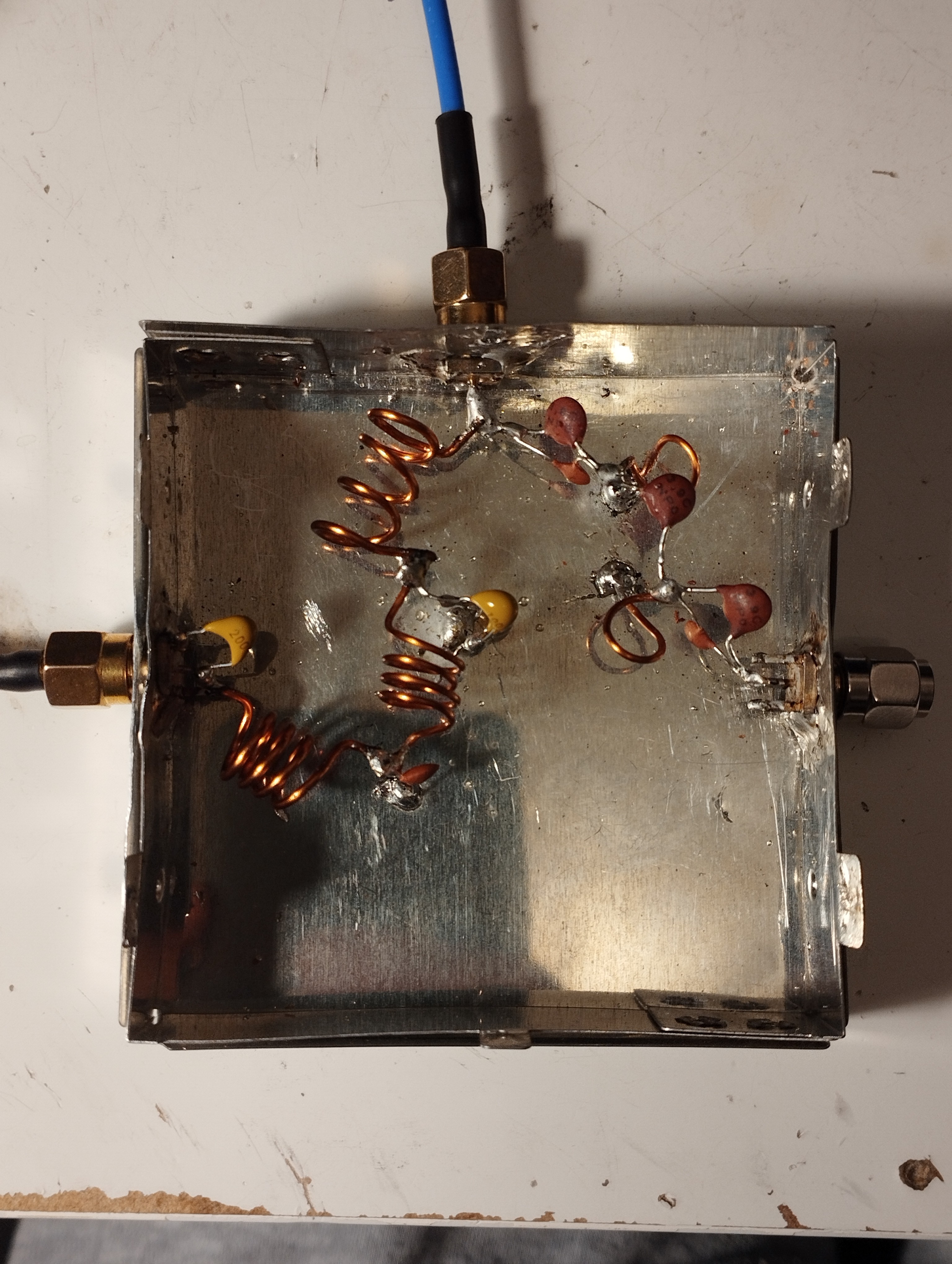
I used a small case 74 x 74 x 22 (H) mm
The 56 nH, 91 nH and 82 nH inductances are obtained with 4 turns of 1 mm enameled copper wire on a 6 mm diameter.
Their different values are set with different length (The higher the length the lower the inductance)
The 15 nH are 1 single turn of 1 mm enameled copper wire on a 4 mm diameter.
Results
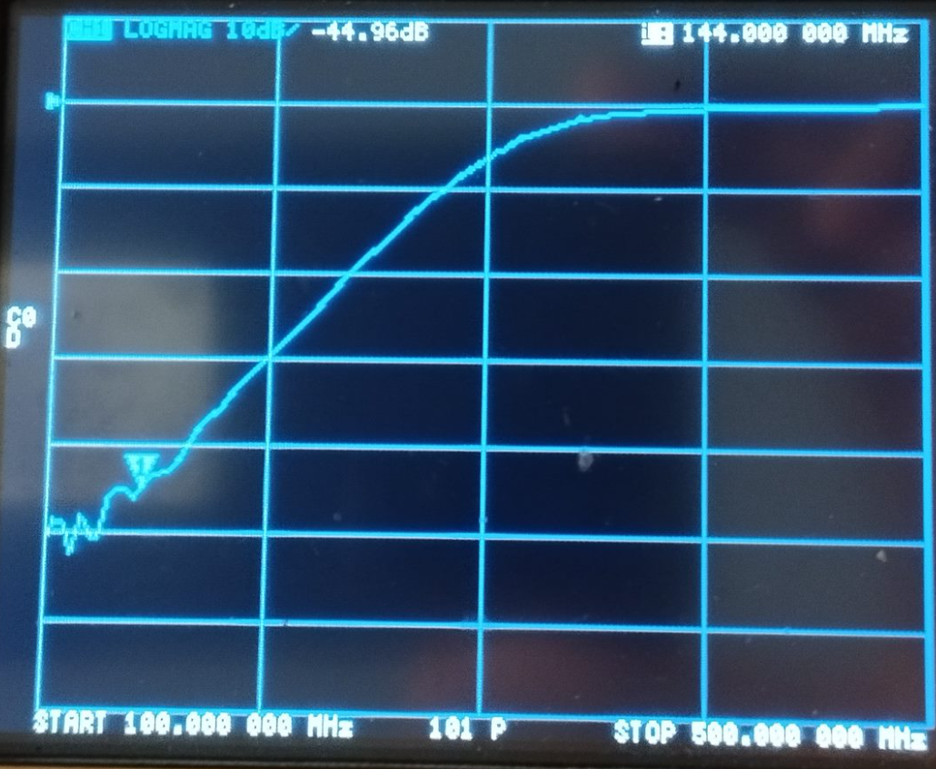
144 MHz side
- insertion loss at 144 MHz = -0.5 dB
- attenuation at 432 MHz = - 52 dB
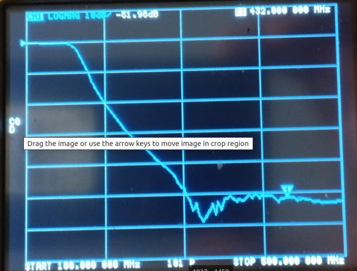
432 MHz side
- insertion loss at 432 MHz = -0.4 dB
- attenuation at 144 MHz = - 45 dB

 Daren Schwenke
 Musti
Musti
 agp.cooper
 Elite Worm
Cool build, I could use something similar for my discone. Wrote this up for the blog, should publish soon. Nice work!