Silícios Lab
Introduction
Arduino is an excellent tool for anyone who wants to develop prototypes. The board has all the necessary resources for you to connect numerous electronic elements, modules and sensors.
However, there is a big problem that makes connecting these devices difficult: the small number of pins for power supply for +5V and GND. This makes connections difficult, as it requires users to connect several wires together and often creates problems with poor contact between connections.
Do you want to download the files for this electronic project? Click on this link and download now!
Based on this problem, we created this development board based on the ATMEGA328P, which will facilitate the creation of countless projects.
Next, we will present the electronic blocks and functionalities of the developed circuit board.
Electronic Schematic of the Project
The electronic circuit of the printed circuit board is divided into 7 electronic blocks. All of them are presented in the figure below.
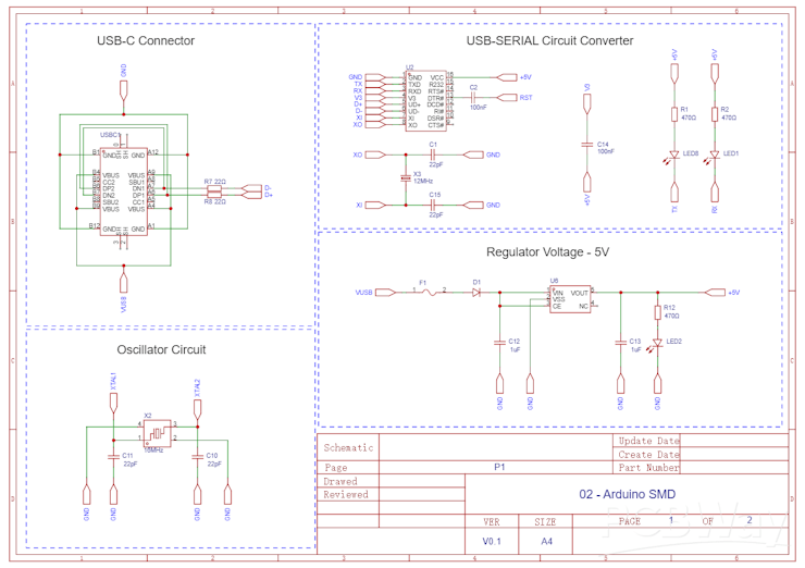
Now we will present each block of the electronic board circuit.
Do you want to download the files for this electronic project? Click on this link and download now!
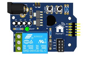
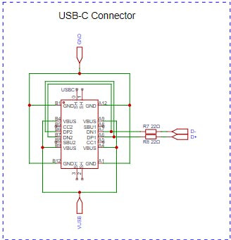
Power supply and USB-Serial converter circuit
This electronic board was developed to be transfer the code and power supply directly via the USB-C connector. The minimum voltage to power the circuit via USB-C is 6.5V. In addition to USB, you can power the circuit with +5V directly from the +5V pins on the electronic board.
The voltage coming from the USB passes through the voltage regulator circuit to supply 5V to the entire electronic board circuit. See the electronic block below.
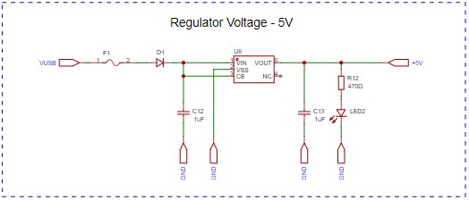
Fuse F1 and diode D1 are used, respectively, to protect the circuit against short circuit and polarity reversal in the power supply.
As previously mentioned, the USB-C port also allows you to transfer code from the computer to the ATMEGA328P Microcontroller. To carry out this process, we need to use a USB-SERIAL converter circuit. Below we have the USB-SERIAL converter circuit.
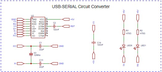
The main element of this circuit is the CH340G USB-Serial converter. In addition, we inserted two LEDs to signal when a data transfer is taking place between the computer and the ATMEGA328P Microcontroller.
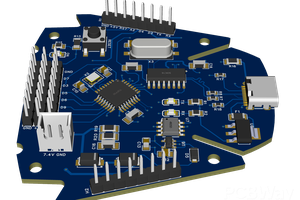
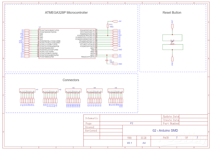
ATMEGA328P Microcontroller Circuit
The ATMEGA328P Microcontroller circuit is made up of 3 blocks: the ATMEGA328P Microcontroller, the oscillator circuit and the reset button for the application.
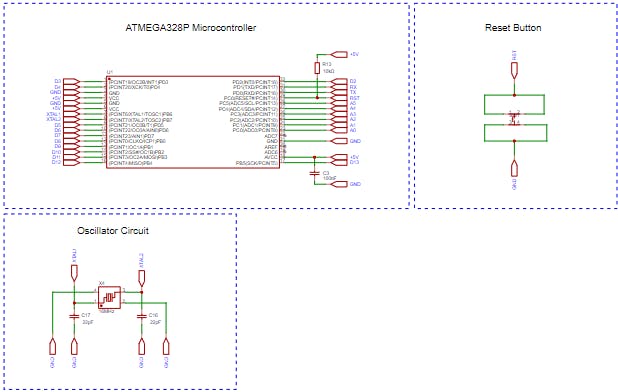
From this circuit, we inserted the male pins on the board to access the ATMEGA328P's digital pins and create power rails.
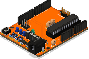
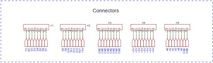
Digital pins and +5V power rails
Below we have the connectors for the digital pins and buses with 8 +5V pins and 10 GND pins. What is the big advantage of adding these buses? As we already mentioned, the Arduino has few pins for +5V and GND. During the assembly process of many prototypes, this makes it difficult to connect circuits. As a way to facilitate and speed up the construction of electronic projects, we inserted these buses.
Next, see the result of the printed circuit board.
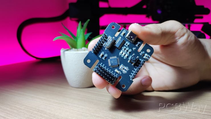
Result of Arduino-based development board
Below, we present some images of the result of the printed circuit board and the extra power pins that were added.

In the figure below we have the extra +5V and GND power pins that were added. Note that the analog pins were placed next to these pins. This makes it easier, for example, to connect and power analog sensors.
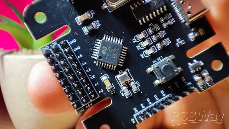
As you can see, most of the electronic components on this board are SMD and use the 0805 package. This makes it easier to assemble manually by any user interested in assembling this electronic board at home. If you do not have the necessary material, you can purchase this electronic board directly from PCBWay.
Final Thoughts
This circuit facilitates the creation of countless electronic projects, especially when the focus of the project is to develop a prototype quickly and easily to test...
Read more »