 danjovic
An LDR's resistance, RLDR can vary from about 100Ω in the sun light, to over 10MΩ in absolute darkness (source).
For practical uses we can consider one order of magnitude above and below the extremes, which in numbers means a resistance variation range from 1KΩ to 1MΩ.
With that in mind it is possible to use the LDR along a voltage divider circuit and calculate the values of the resistors so the output voltage will match a desired range as long as such range is reasonably within the voltage rails, for instance, In a recent project I needed to use the LDR reading from an 8 bit ADC to drive a 5 bit soft PWM, then a range of 128 counts could be easily shifted right to get me the values from 0 to 31 (and avoid a floating point division math).
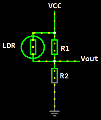
We have then 2 unknown variables, R1 and R2 and two known resistance values and their expected output:
- LDR in dark, R = 1MΩ, Vout = Vdark
- LDR in brightness, R = 1kΩ, Vout = Vbright
It is reasonable to consider that Vdark and Vbright will be symmetrical around Vcc/2, and to perform the calculation of the resistors we can normalize the voltage value to the resolution of the ADC (e.g. use a value of 256 in the math instead of 5V).
Rewriting the terms, considering the half of the ADC scale is 128 and half of the desired range is 64:
- LDR in dark, R = 1MΩ, ADCount = 128 + 64 = 192
- LDR in brightness, R = 1kΩ, ADCount = 128 -64 = 64
That can be solved using the voltage divider equation:
- ADCcount = ADCrange * R2 / ( R2 + R1//Rldr )
Along with the parallel resistance equation
- 1/Req = (1 / Rldr) + (1 / R1)
Combining both:
- ADCCount = ADCrange * R2 / { R2 + [ 1/ ( 1/Rldr + 1/R1 ) ] }
There are several ways to perform the math, including Wolfram Alpha, and the equation to find the resistances can be calculated using the following string
(64+128)=256*(r2)/(r2+(1/(1/1000+1/r1))); (128-64)=256*(r2)/(r2+(1/(1/1000000+1/r1)))
The calculated values will hardly be an exact value, but the E24 series can provide values close enough to get the desired counts from the ADC
| Resistor | Calculated Value | Closest E24 Value |
|---|---|---|
| R1 | ~8072Ω | 8K2 Ω |
| R2 | ~2669Ω | 2K7 Ω |
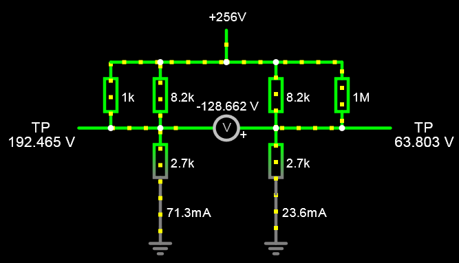
It is possible to use the Falstad online simulator to check how good the picked values are, and of course to fiddle with the values. To save time it is possible to use the link below the access the simulation.
INotice that the Vcc voltage was set to 256 to make it easy to check the ADC count values from the LDR in brightness (left) and in darkness (right). The difference between readings is shown in the middle. Also notice the E24 series values provided good results (no need to use precision resistors)
Epilogue:
if the LDR is exposed under extreme conditions the resistance values canreach the maximum values and the voltage range will differ from the calculated, therefore it is necessary to limit the range in software. It will also be necessary to subtract the value from the minimum expected value to have a light reading value starting from 0 (zero).
#define VMAX 192
#define VMIN 64
...
tempValue= adcRead( LDR_CHANNEL);
if (tempValue > VMAX) lightValue = VMAX;
if (tempValue < VMIN) lightValue = VMIN;
lightOutput = tempValue - VMIN;
...
In my case specifically all that's left to do to call it a day is to shift right the light output value to have the Toff within the 0-32 range.
tOFF = lightOutput >> 2;
Discussions
Become a Hackaday.io Member
Create an account to leave a comment. Already have an account? Log In.