Close
0%
0%

next.module

Flexible, compact and beautiful modular prototyping framework

Public Chat
Similar projects worth following
The concept of the next.module project isn't new. It is a range of compact modules that can be combined to create a highly sophisticated and complex, but at the same time quite compact device. It's easy and accessible even for novice DIY enthusiasts.

Each module has one or more basic functions. It could be a memory module, sensor module, I/O extension module, interface module, or a module with display, buttons, etc.
Modules are well-tested and work reliably. Users have access to complete schematics as well as a lightweight SDK with a simple API for interacting with each module.

At the same time, users can connect a standard breadboard to the next.module modules and make their own DIY module or implement any desired functionality.

Modules design

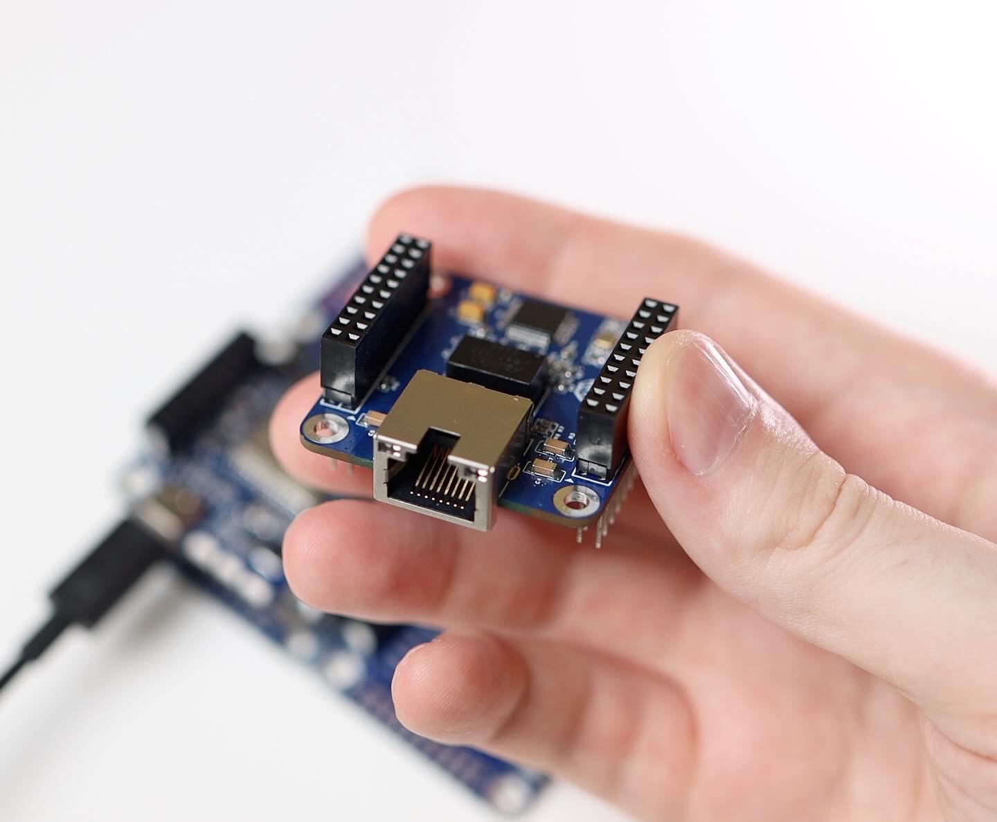
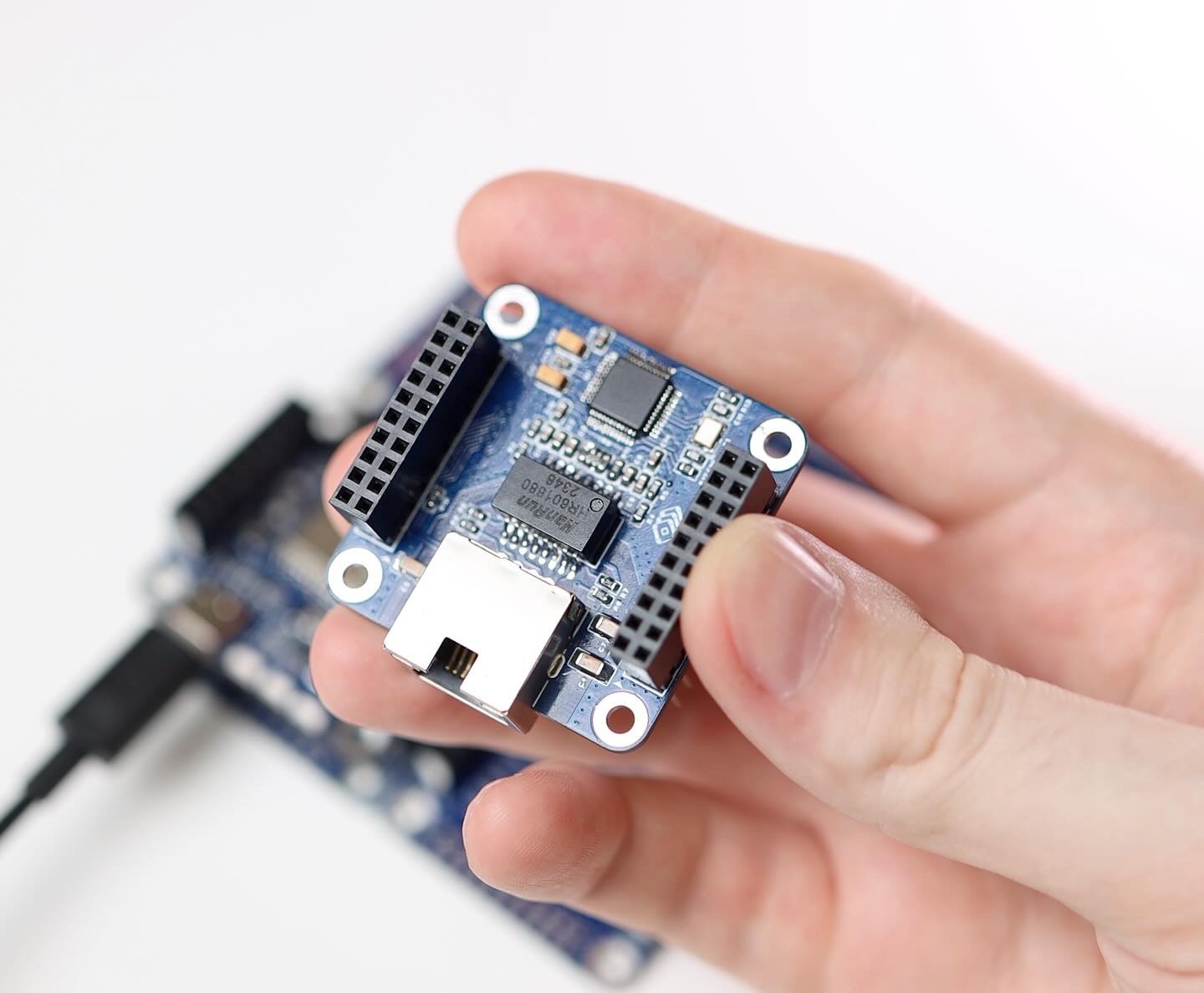
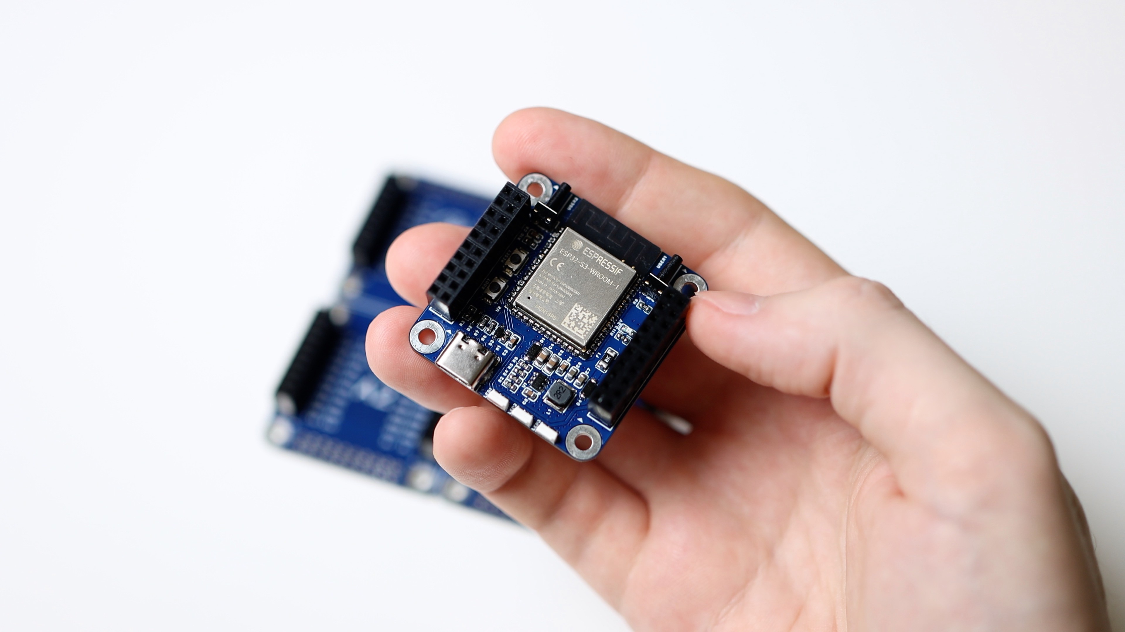
I have always wanted to use small modules. As much as possible and reasonable in terms of fitting all the components of a fully functional assembly on them. Ideally 50x50mm or even smaller.

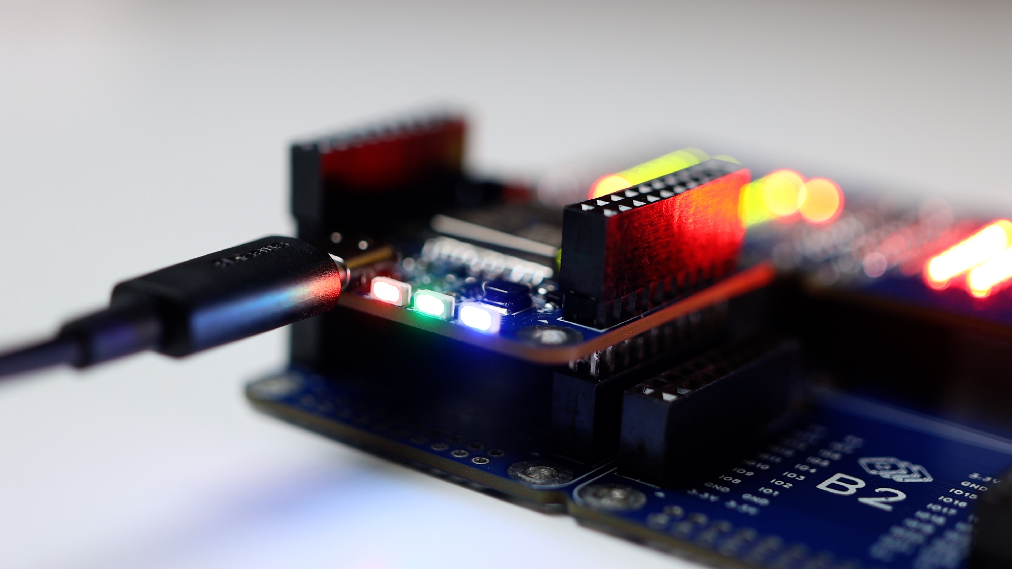
The electrical connections between the modules must be reliable, the modules must be firmly attached together to prevent the structure from coming apart with any careless movement on the table. Additionally, the contacts need to be reliable to ensure that they do not fail.
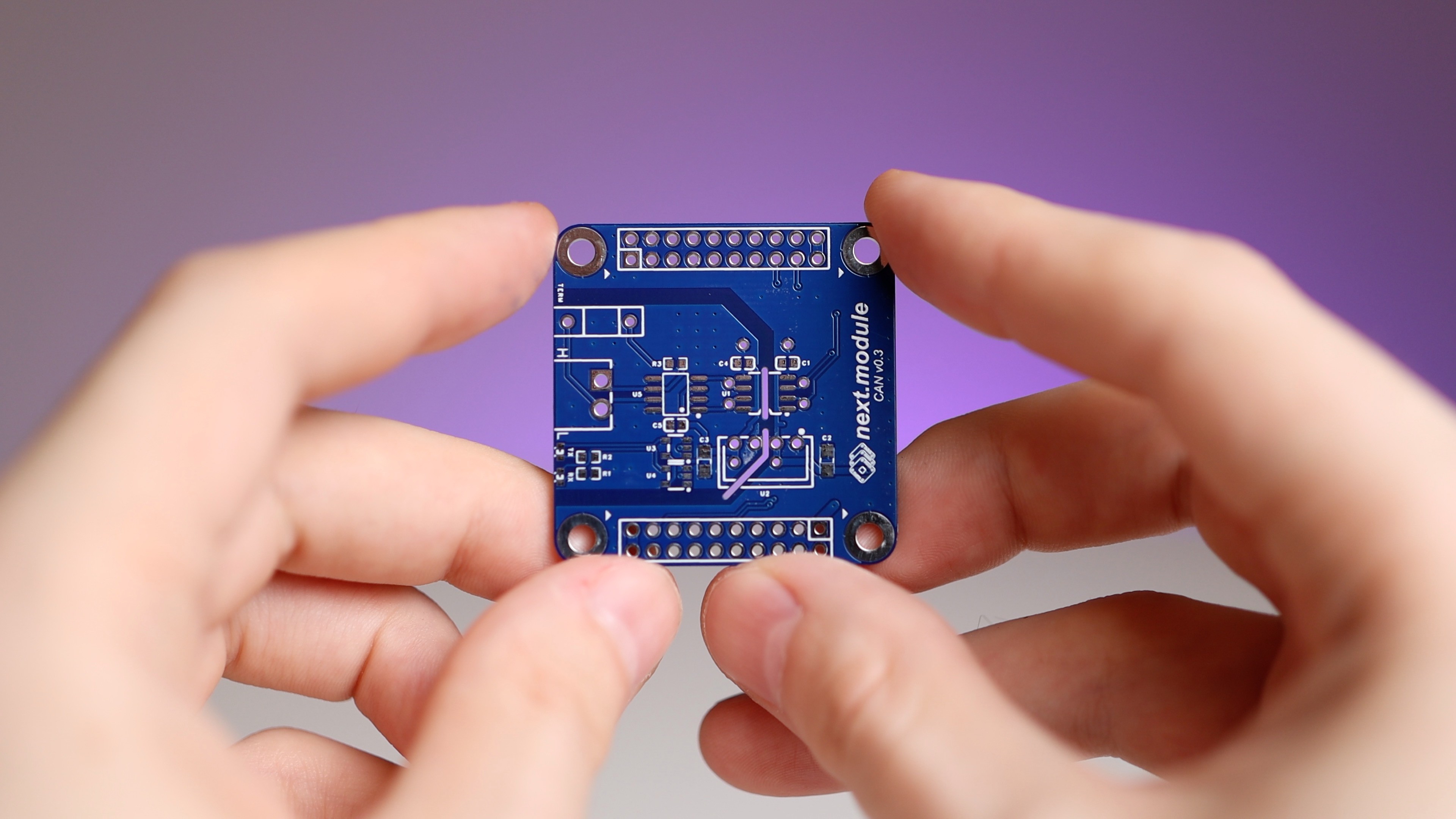
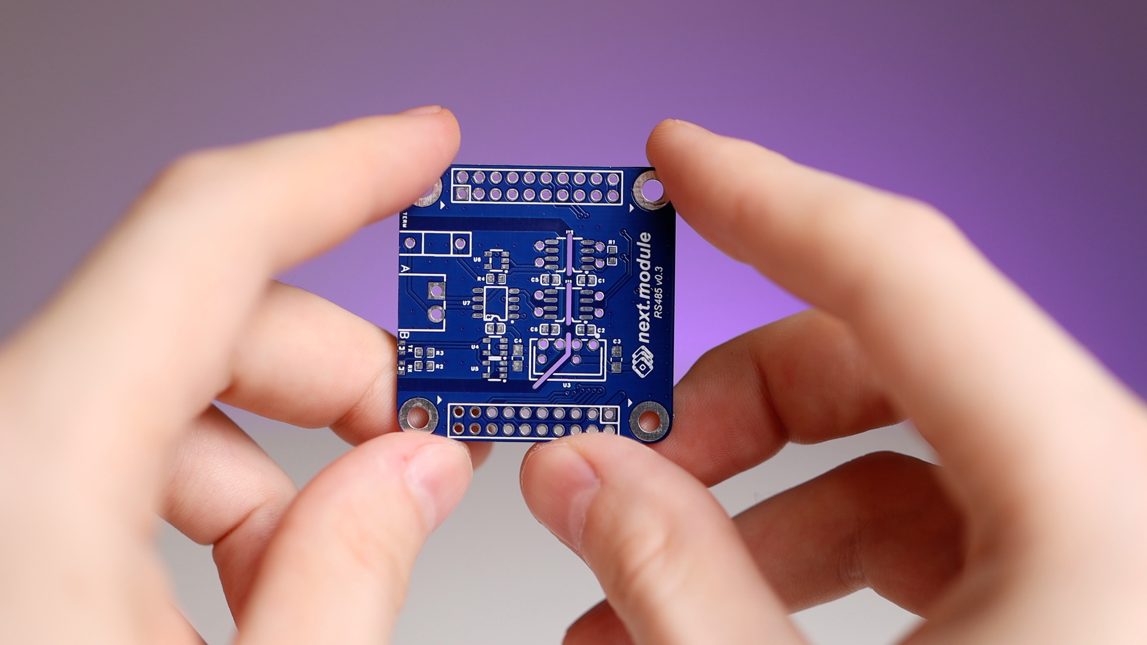
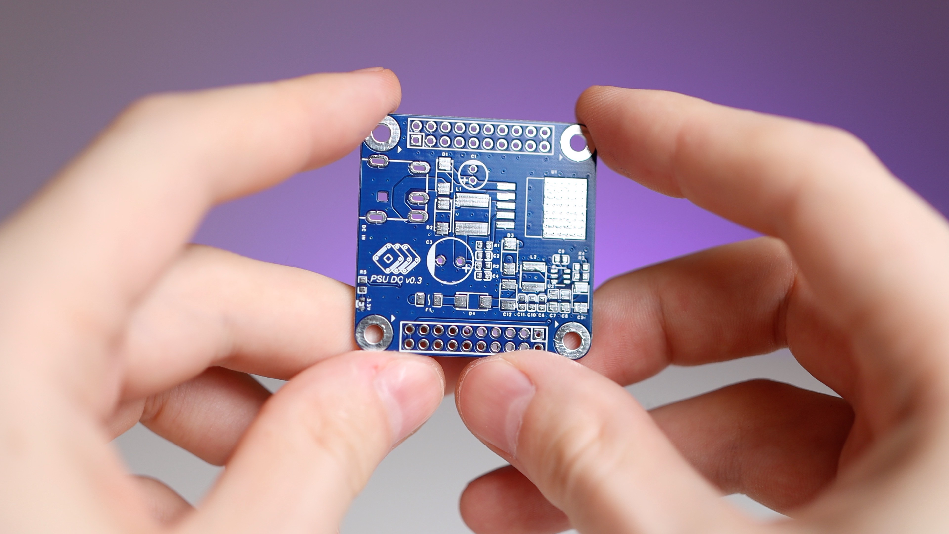
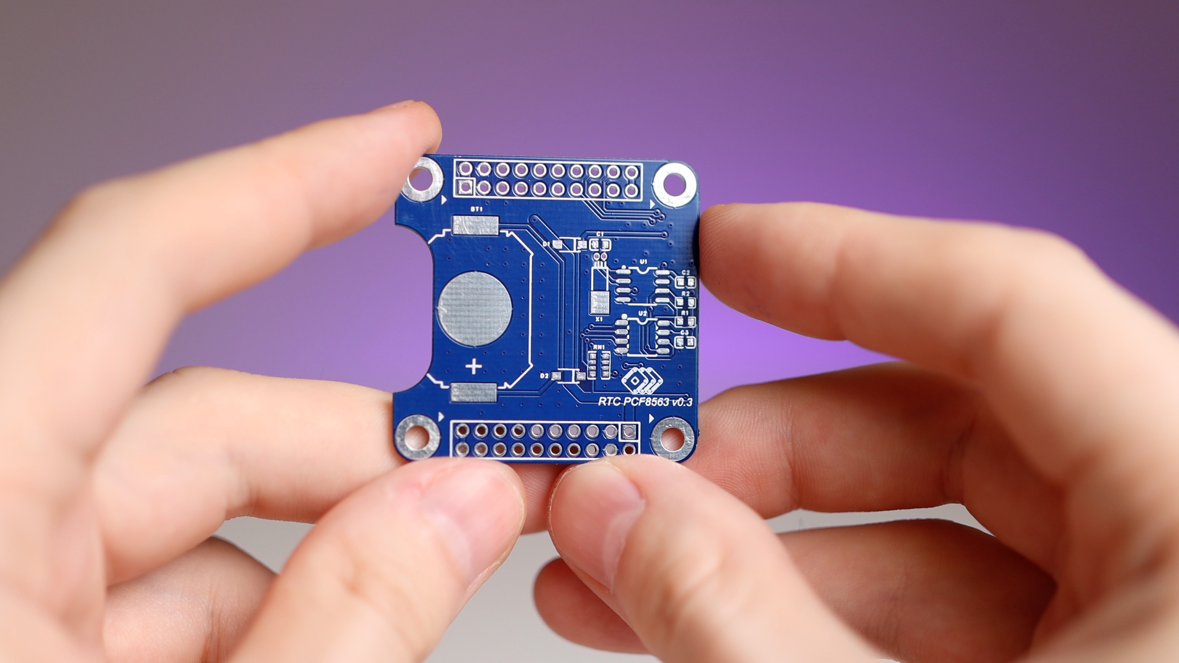
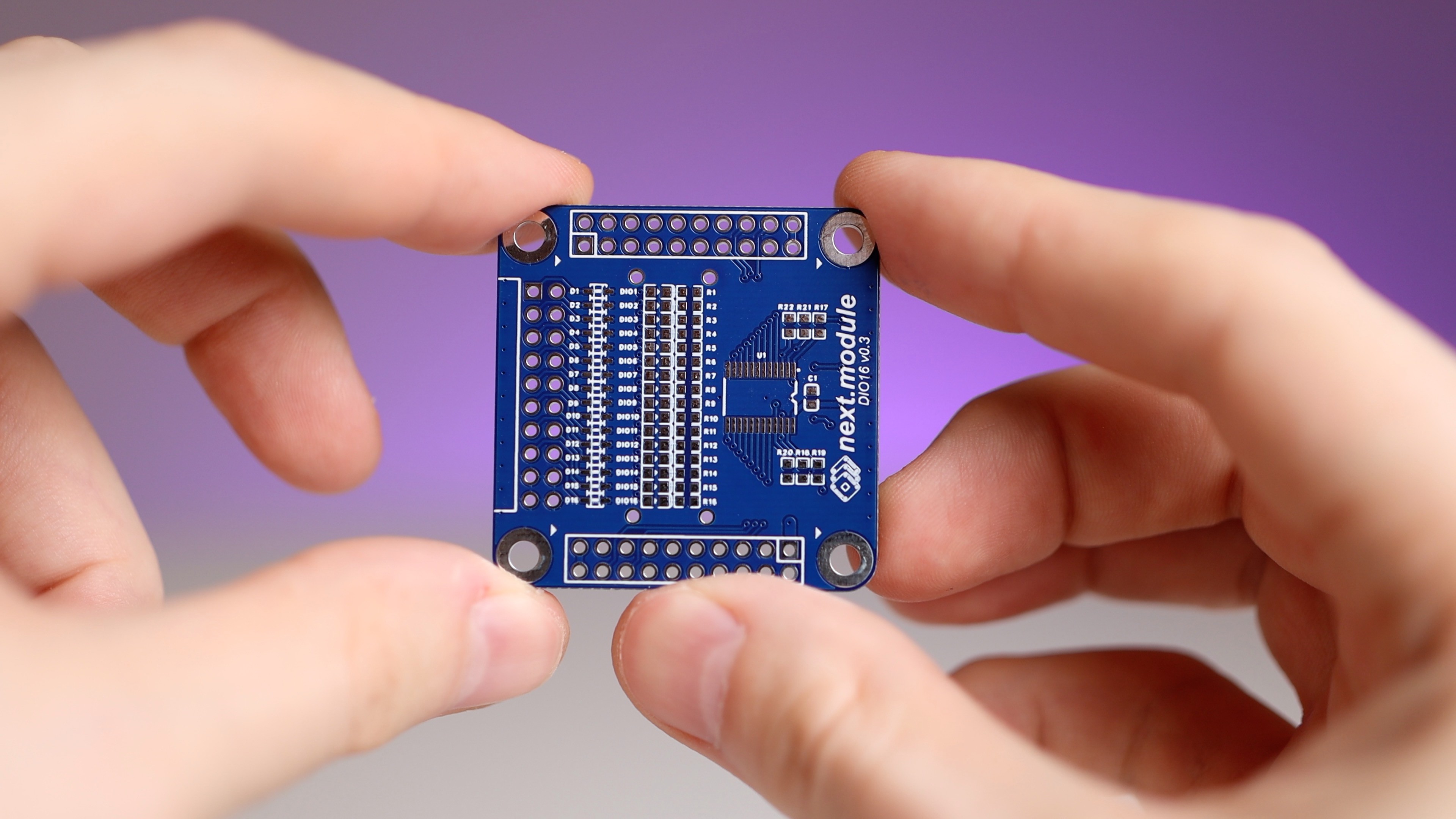
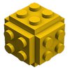
To address these concerns, I have designed the printed circuit board for the module in this way.

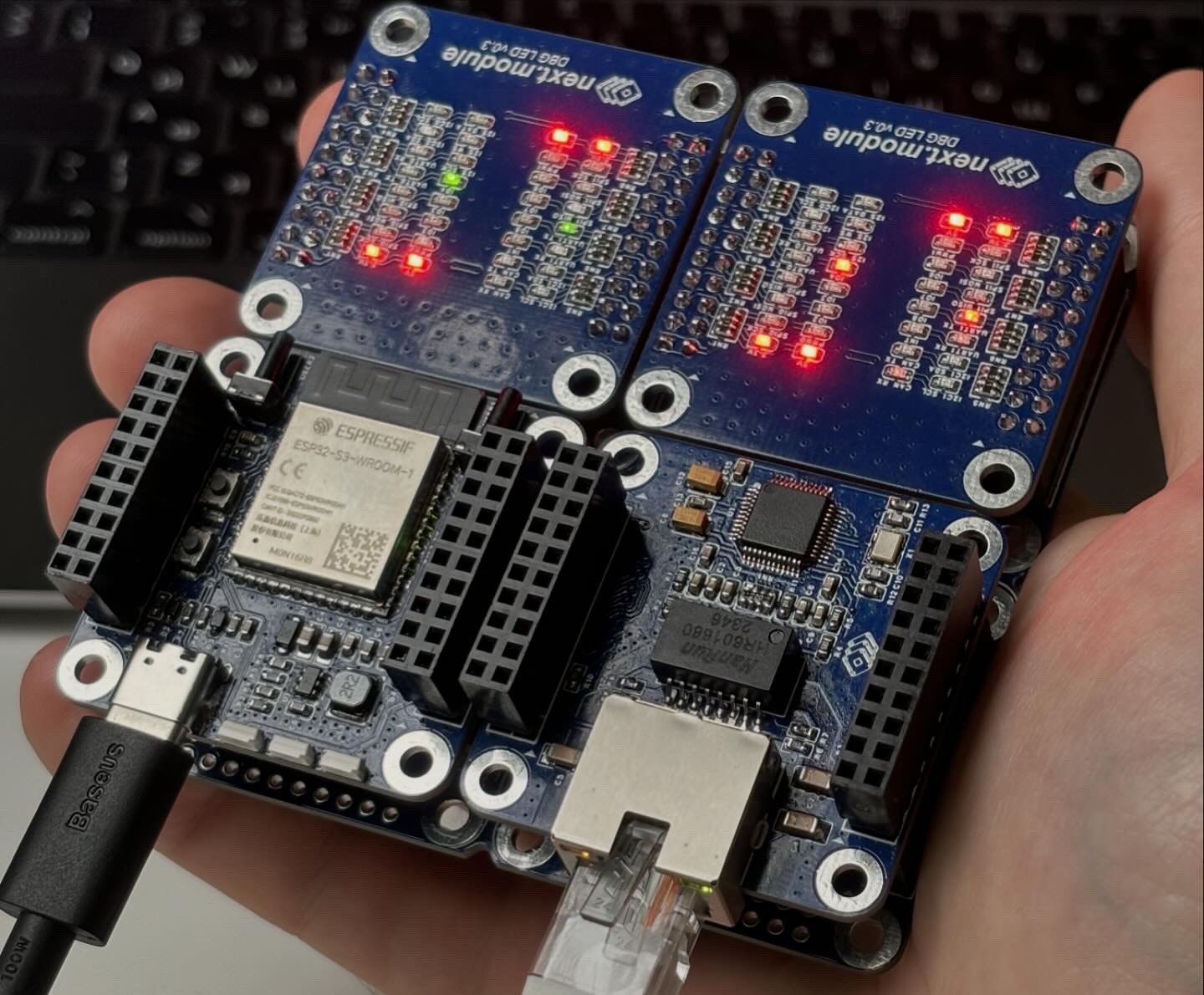
Expanding the assembly vertically is good, but horizontal expansion is still necessary. Otherwise, with a large number of modules, we will end up with a narrow and unstable rack. Horizontal expansion is also possible using HUB boards. That is, in one of the rows, a larger HUB board is placed, which has a multiple of the module's dimensions (for example, 2x1, 1x2, 2x2, 3x2, etc.). It has all the same inter-module connectors at the top and bottom and mounting holes as conventional modules. Such HUBs allow you to run multiple modules from different racks in parallel and connect them physically.

The main disadvantages of this solution are that the HUB takes up one tier in the assembly and the mechanical connection between racks is weaker than if there were no HUBs.

Modules placement in the case

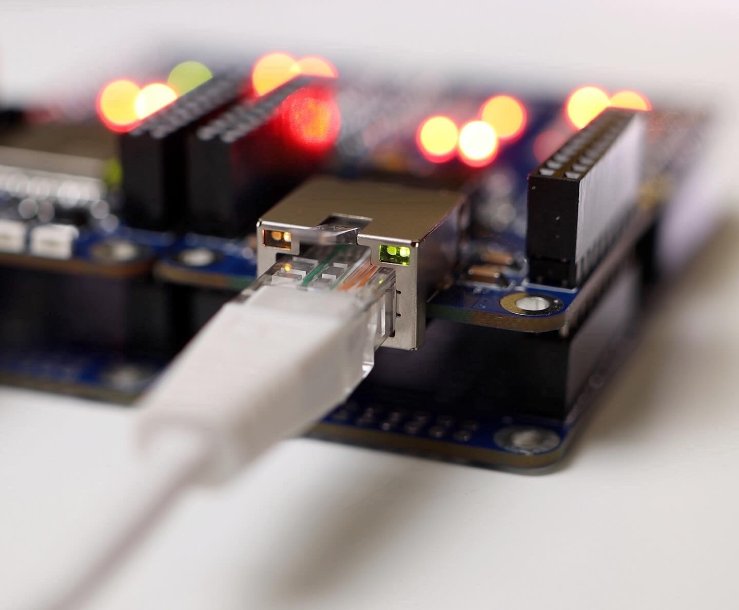
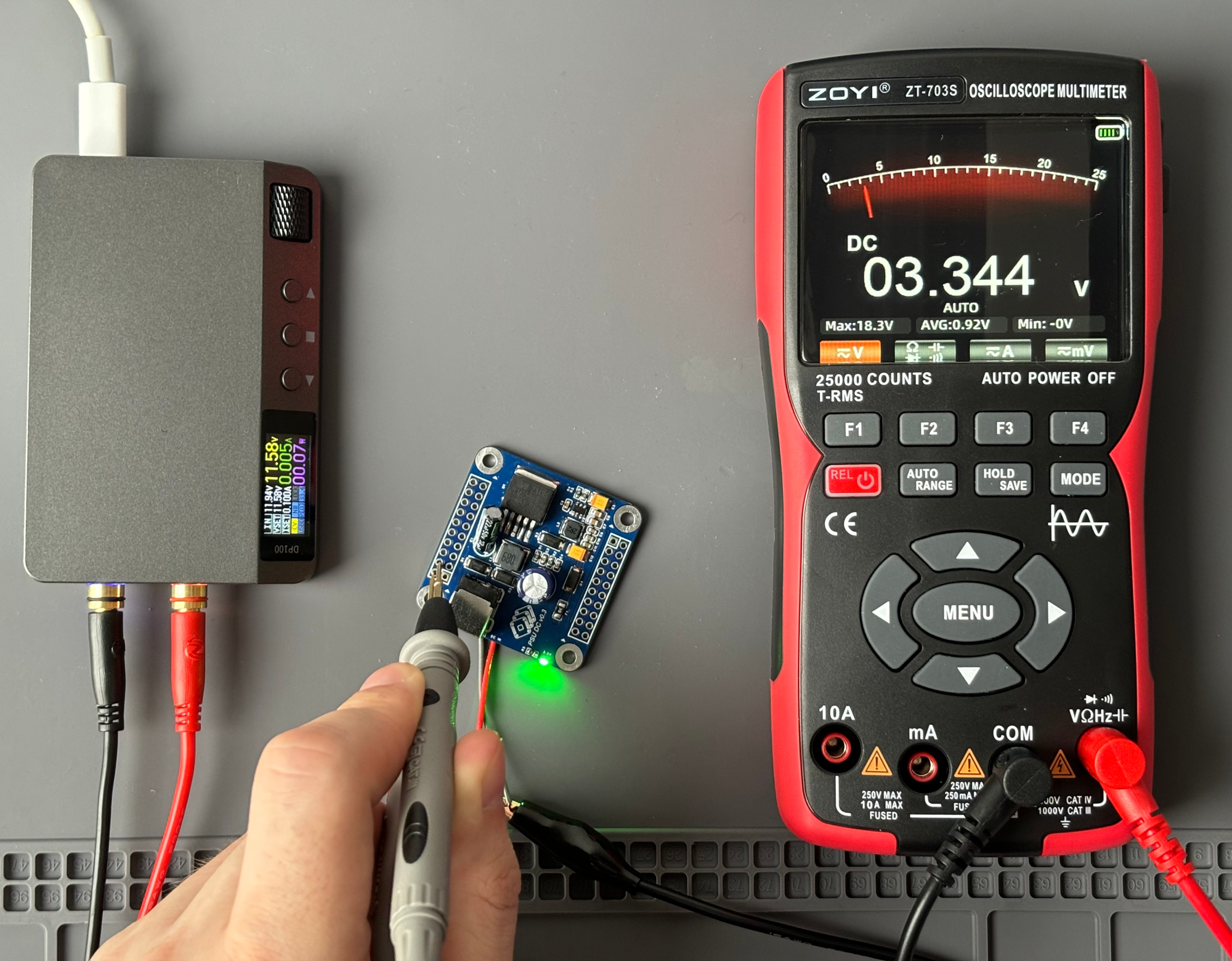
Connectors for external connections are located with a 2 mm protrusion beyond the board. This is necessary so that the connectors of the device are not recessed into the case and do not stick out of it. A case with a wall thickness of 1.6 mm can be 3D printed. The remaining 0.4 mm gap is the space between the board and the case wall.

Brass stands, which are used to attach modules to each other, can also be used to assemble modules in a case. The M3 screw can be used to fasten the module rack to the chassis. Another option is to use M3 injection nuts:

Then, the first level module is applied, the first level stands are screwed in, the second level module is applied, etc. In a cut it looks like this:

Subscribe and share

The project is currently in active development. If you are interested in the idea, please subscribe to the project and share it with your friends who may also be interested.

Now you can find news about next.module project in the "Project Logs" section.


  • ETH W5500 module testing

    Ruslana day ago 0 comments

    The ETH W5500 module is working!

    I was concerned about possible mistakes in the wiring of the chip on Ethernet side, but everything is ok.
    There are 2 issues:
    ✅ I forgot to add a 1 Mohm resistor that shunts oscillator
    ✅ The LEDs in the connector are too dim

  • ESP32S3 module testing

    Ruslan2 days ago 0 comments

    All prototype modules are 95% assembled (I don't have all the details).

    Today I will tell you about the ESP32S3 CPU module:

    • ESP32S3 is flashed and debugged via USB-C. No debuggers and USB-UART are needed.
    • RGB-LEDs are working. The implementation of the WS2812 chip protocol is hardware-based, using SPI or RMT. Everything is already included in the ESP-IDF and works great.
    • The green LED 0603 (powered by 3.3V) is too dim.
    • DC-DC based on TPS563201DDCR works well, but needs to be tested at currents up to 1.5-2 A.
    • Intermodule connectors are convenient. Connect-disconnect quite easily, do not bend when removed. The only thing is that the pins are too long. I will shorten it in the prototypes.

  • Prototype testing started

    Ruslan05/06/2024 at 07:42 0 comments

    next.module prototype testing started!

  • PCBs for prototypes

    Ruslan04/25/2024 at 18:54 0 comments

  • Debug modules: DBG LED

    Ruslan04/16/2024 at 16:20 0 comments

    A very simple and cheap debugging module with 32 LEDs displaying the status of the pins on the intermodule interface and the presence of supply voltages

  • Audio modules: AUDIO OUT

    Ruslan04/16/2024 at 16:18 0 comments

    Module with DAC for stereo audio output to 3.5" analog jack

  • RTC modules: RTC PCF8563

    Ruslan04/16/2024 at 16:14 0 comments

    Module with RTC, battery and EEPROM

  • PSU modules: Multiple PSU modules in one device

    Ruslan04/04/2024 at 19:09 0 comments

    This schematic diagram explains how multiple PSU modules are connected in one device

  • PSU modules: PSU AC

    Ruslan04/04/2024 at 19:05 0 comments

    This module allows you to power your device with AC power source.

    A wide range of input voltages allows this module to be used with 115V or 230V power outlets.

  • PSU modules: PSU DC

    Ruslan04/04/2024 at 18:53 0 comments

    This module allows you to power your device using a common DC power source.

    The input voltage range is from 7 to 40 V.

View all 20 project logs

Enjoy this project?

Share

Discussions

Samuk wrote 03/30/2024 at 16:17 point

It's a shame the screen one isn't pin compatible with your boards. I might see If I have the skills to edit it to be pin compatible. I suspect not, but I'll have a look.

  Are you sure? yes | no

Ruslan wrote 03/30/2024 at 18:34 point

I don't think it makes sense. I will develop modules with displays in the next iteration of development. I have already purchased several high-quality and interesting displays (OLED, IPS, Memory LCD, etc.).

  Are you sure? yes | no

Samuk wrote 03/31/2024 at 12:03 point

I'm interested in open hardware, so it may make sense for me.

  Are you sure? yes | no

Samuk wrote 03/29/2024 at 22:07 point

This is a very similar project that makes the source available and has a nice screen https://pro.lceda.cn/editor#id=8624bf3d43ba4732bb256c08aafe186b,tab=*5bff943b3fc4443f894cb3ea0447e7f6

  Are you sure? yes | no

Ruslan wrote 03/30/2024 at 08:34 point

Very good

  Are you sure? yes | no

Samuk wrote 09/05/2023 at 23:45 point

For my part I'm currently interested in the v7 version of the Mikroe system: https://www.mikroe.com/mcu-cards?type*=7th-generation,7th-generation

I might do an adaptor so the Micromod cards can drop into them.

  Are you sure? yes | no

VASILIS VORRIAS wrote 09/03/2023 at 10:25 point

Hi ,Ruslan  

I found this space after a Samuk made a post in my Git-lab space  by pointing out your project

Excellent idea.

I used this ESP32 pin out on our M10CUBE sensor module some years ago.

https://hackaday.io/project/171770/logs?sort=oldest&page=2

Here is what we came up after years of experience in Automation Industry

https://gitlab.com/m10cube/m10

We believe that this footprint is the golden rule in dimension

Your idea is fine and applicable but I believe M10CUBE drive project building to another level.

These are  (among others):

- Raspberry Pi bus

- 90X90 mm real estate for embedding a lot of sensors and other stuff.

- 100x100 mm Final box outside dimensions  (That is very convenient volume). DIN RAIL or wall mounted. Some models already build.

- Stuck-able or freestanding using 40 pin flat cable (find it everywhere left from old IDE HD)

- Robust platform to build Industrial IOT prototypes but at the same time to be a production module ready as well

- Already working many Industrial I/Os . A lot is comming on (BLE mesh, CM4 board, LTE-M, NB-IOT, DECT NR+ and more...)

Can you join us on a similar idea? You have skills we believe will give M10CUBE project a boost and every body can benefit..

We need fresh ides to drive it sky high.

Thank you

Vasilis

  Are you sure? yes | no

Ruslan wrote 09/15/2023 at 19:58 point

Hi, Vasilis. Sorry for late answer

Thank you for your interest!

It's amazing how similar ideas are born in different people's heads)
I liked your project. I don’t know yet what could be improved, but I will follow it and participate whenever possible

  Are you sure? yes | no

nigel wrote 06/07/2023 at 11:28 point

This is very interesting. It reminds me of Digilent PMods with a lot more options.

  Are you sure? yes | no

Similar Projects

Does this project spark your interest?

Become a member to follow this project and never miss any updates