 Max.K
Max.K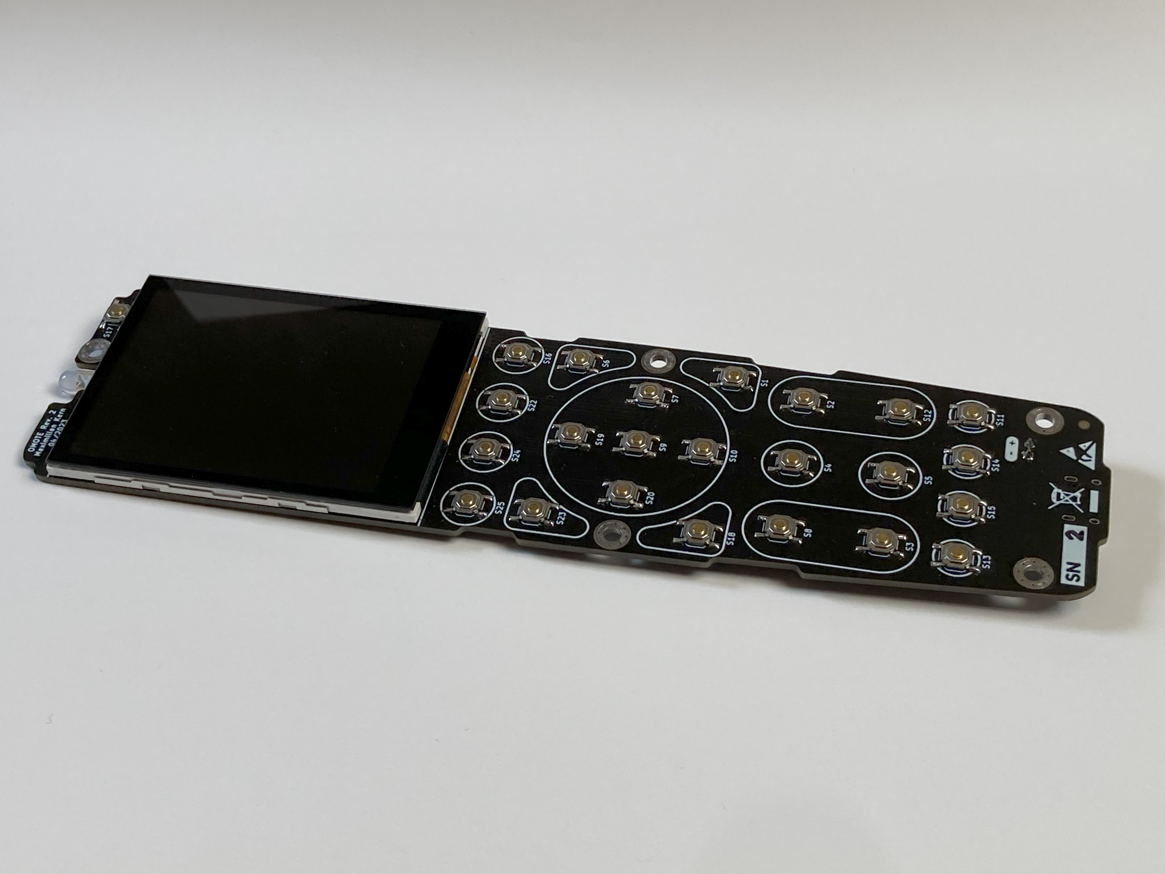
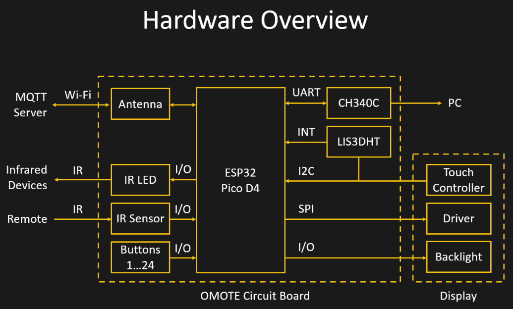
Because of its wireless interfaces and low power consumption in sleep mode, the ESP32 is an ideal choice for this project. I included a CH340C serial adapter, so it can be programmed using a USB Type-C port. The same port can also be used for charging a Lithium-Ion battery by including a charging IC.
While the display is powered up and the ESP32 is not in sleep mode, the device quickly drains the battery. To minimize the time in this active mode, a LIS3DH 3-axis accelerometer can detect if the device is moving. Via i2c the ESP32 can check if it stopped moving for a while and power down. An additional interrupt pin wakes the controller as soon as the remote is picked up again.
To save on IO pins, the 24 tactile switches are arranged in a 5x5 grid. Each row is connected to a digital input while the columns are constantly toggled in software. This way, only 10 instead of 24 pins are needed. The five input pins can also be used to wake the device up from sleep. For this, they need to use the same logic (active high) as the accelerometer interrupt and the five outputs must remain High.
The display is connected to the controller via SPI for the pixel data and i2c for the touchscreen. I am using the ESP32s hardware SPI pins to take advantage of the full 80MHz that the controller supports. The displays backlight can be turned on by a DMG2301 MOSFET. Another one of these MOSFETs is used to switch of the display logic and touch controller since they draw some power as well.
A third MOSFET is used to control the infrared LED. It uses a very small, 3.3 Ohm series resistor to maximize its range. A Vishay TSSP77038 IR Sensor enables it to read and decode commands from other devices.
I had already created the basic outline of the PCB in Fusion360, so I simply imported it directly into KiCad. A major challenge was placing the Wi-Fi antenna in such a way, that it is not obstructed by the metal display frame or the hand that holds the remote. The only possible location was the top corner of the PCB, right next to the IR LED. I had used the ESP32-WROOM module previously, but it was too big to fit and half the pins would end up on the edge of the PCB. Instead, I switched to the ESP32-PICO-D4. It’s a 4x4mm System-On-Package that contains most of the components of the WROOM module. An external antenna, like in this case a small chip antenna, can easily be connected to the Pico. Trace antennas would also be an option, but chip antennas usually are more robust against influences like the 3D printed case. The trace line between the ESP32 and the antenna should normally be impedance controlled which is tricky on a 2-layer PCB. I can get away with this by keeping the length below 1/10 of the wavelength (12mm for 2.4GHz). I also ensured that there is a continuous ground layer below the trace line and ESP32 and that vias are placed along the edges.
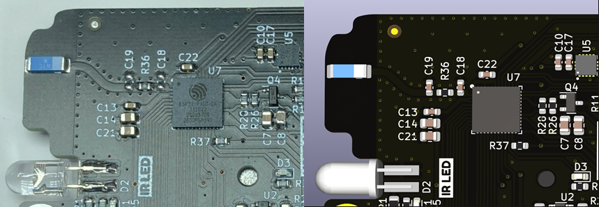
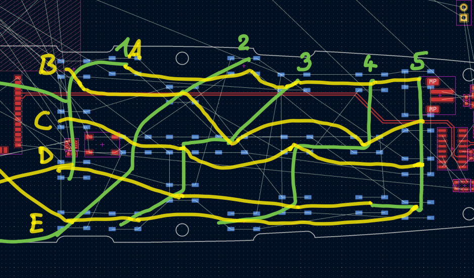
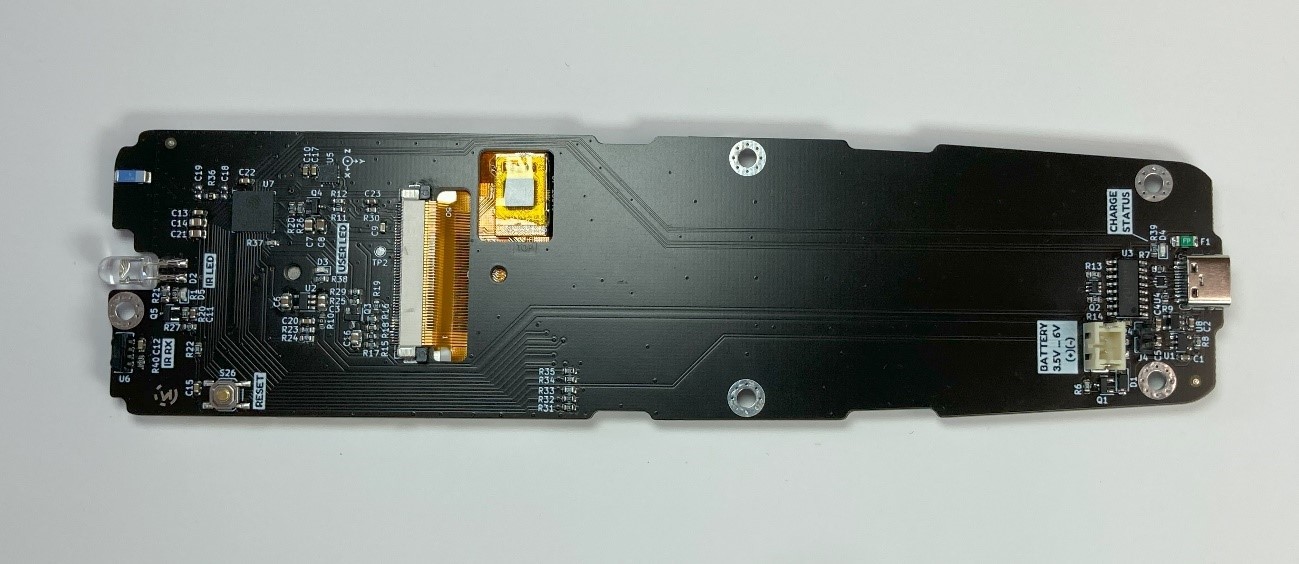
I am using a regular 5mm infrared LED that is soldered to the top edge of the board. The IR receiver is placed next to it. A 40 Pin connector is used for the display, while its cable goes through a cutout in the PCB. Another cutout makes room for the touch controller that protrudes the display cables. This allows the display to be glued flat on the PCB. On the lower end of the PCB, there is room for the USB Type-C connector, the serial adapter and the charging IC. The only components on the other side of the board are the tactile switches. For the button matrix to work, these switches need to be arranged in a 5x5 grid. It was a little tricky figuring out the placement so the traces don’t cross.
Since the ESP32-PICO-D4 only has pins on the bottom, it needs to be reflowed. Luckily, I have a small hot plate that I could put to proper use for the first time. Since the hot place is only 3x3cm, I had to move the board around during soldering. For solder paste, I used the MECHANIC XGZ4 and set the plate to around 220°C. As this was my first try at reflow soldering, I was amazed at how clean the solder joints look afterwards.

With the final software, the board draws around 32uA in sleep mode and 150mA in active mode with the display and ESP32 turned on. Using Wi-Fi adds another 80mA to the active mode consumption. Assuming the remote wakes up one every hour for 10 seconds, the 2000 mAh battery will last around 180 days.
Discussions
Become a Hackaday.io Member
Create an account to leave a comment. Already have an account? Log In.