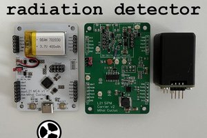
Rationale and goal
An arbitrary waveform generator is a standard tool for almost every budding electronics engineer. However these devices are costly - Even the relatively cheaper ones with specifications like 150MS/s, 50mhz, 14-bit cost above $300. There are under $10 signal generators, but their usage is very limited and they certainly cannot generate arbitrary waveforms. The $300 to $500 range devices are very reliable, accurate and get most of your work done including low frequency RF applications - However is this really necessary? Practically what most engineers need 90% of their time is a waveform generator with high enough bandwidth (> 25 MHz) a corresponding sampling rate (> 100 Msps) and 8-bits of 99.99% accurate resolution with 2 channels which can be used simultaneously. The internal clock should also be good (< 100 ppm at least). Our ultimate goal is to create such a device under $50 production cost.
Source code
Operation
Design - High Msps bit pattern generator
The problem with using standard low cost development boards is the that they cannot generate n-bit signals consistently aligned to a clock edge at high sample rates. Using something like a GPIO is never a good idea since buffering the signal and aligning it to a clock requires additional hardware which makes the whole thing costly. But what if a board already had an inbuilt mechanism to do so? With the launch of the Raspberry Pi Pico a few years back, we finally have such a board. It has a special hardware module called PIO (programmable I/O) which allows the programmers to write some specialized assembly code which achieves exactly the same thing. It also works a very high speeds (upto the native sys-clk speed which is 125 MHz). Even with additional overhead from running code, reaching 100 Msps should be easily achievable. Furthermore this gives a few more advantages -
1. The whole thing is software based and comes with all the goodness of software - Easy updates and changes. Open source contribution and development prospects. Hardware independence etc.
2. High speed DACs generally have either Parallel CMOS, LVDS or JESD204B interfaces. Instead of using complex FPGA we can easily achieve all three interfaces with Pico's PIO programming and additional software. So this makes the core bit generator modular as well. So it can be adapted into other hardware.
For the current proof of concept, we have chosen to have a 8 bit DAC with a CMOS interface. Note that the Pi Pico has more than enough pins free to support higher resolutions. The connections for Pi Pico are as follow -
                +--------------------------+
          GP00 -|                          |- VBUS  <--- Vin (5v)
          GP01 -|                          |- VSYS
          GND  -|                          |-  GND
          GP02 -|                          |- 3v3E
          GP03 -|                          |- 3v3O  ----> 3.3V ref for level converter
          GP04 -|                          |- ADC_VREF
          GP05 -|                     ADC2 |- GP28
          GND  -|                     AGND |-  GND
          GP06 -|          I2C1_SCL / ADC1 |- GP27
          GP07 -|          I2C1_SDA / ADC0 |- GP26
          GP08 -|                          |-  RUN
          GP09 -|                          |- GP22
D0 <----  GND  -|                          |-  GND
D1 <----  GP10 -|                          |- GP21
D2 <----  GP11 -|                          |- GP20
D3 <----  GP12 -|       SPI0_TX            |- GP19
D4 <----  GP13 -|       SPI0_SCK           |- GP18
D5 <----  GND  -|                          |-  GND  <---- Ground
D6 <----  GP14 -|       SPI0_CS / UART0_RX |- GP17  ----> UART RX
D7 <----  GP15 -|       SPI0_RX / UART0_TX |- GP16  ----> UART TX
                +--------------------------+
The D0 to D7 are the digital pins outputting the bit pattern. We will use a serial console to control the whole thing which will be connected to GP16, GP17. The board will be powered via VBUS and GND. We also need a 3.3V ref since a logic level converter is necessary to convert to 5V logic level.
Design - DAC and power supply
For the DAC we have chosen a classic as well one of the most simple - DAC0808. While this DAC has a sample rate of only 6.6 Msps it is reasonably high enough for our proof of concept. It also features a parallel CMOS interface which is staple for high speed DACs. Since the DAC requires a negative voltage supply, we have used a TC7662A charge pump. The DAC also needs a reference...
Read more »
 mihai.cuciuc
 mircemk
 Evangelos Petrongonas
 StephanStrassleRojas
I do like and am interested in projects like this, but there are some things in this project I don't agree with.
First, there are quite a lot of cheap (Chinese) function generators starting from around EUR80 which are quite capable. They have an FPGA and an stm32 (or equivalent, often GD) to control the thing, combined with an R-2R network and some high speed opamps.
A project like this is much more likely to compete with those instruments then with the likes from Siglent or Keysight. I have a cheap JDS6600 myself, (I bought the cheapest variant 10MHz or 15MHz or so, as that is plenty for my need) And the R-2R network works, and it works up to a high enough frequency, but it's main problem is linearity. For just 10 bit you need (at least the most significant bits) to be within a 0.1% tolerance, and even then the 10th bit is near getting lost in noise. But this is quite easily fixed with hand sorting. The exact resistor values are not important, as long as their relative values are correct. And you really want a lot of bits for a function generator like this, because it allows you to do amplitude corrections in software without extra hardware (except for a few very coarse steps). A separate DAC makes it more expensive relatively fast, while most hobbyists would be fine with hand sorting 20 or so resistors, especially if there is some explanation in the manual on how to do that accurately with limited measurement equipment.
But mostly, I do wonder what this Raspi Pico is capable of. The most critical part is glitch free wraparound of the buffer, and switching buffers when amplitude or frequency changes. (it's nice, but not so critical if this can be done glitch free too).
What would be the maximum achievable 16-bit (to keep it simple, just a port) glitch free update rate from the pio peripheral?