 Michael Gardi
Before sending the PCB off for fabrication I wanted to do a sanity check on some of the circuits I had laid out. For instance I wanted to make sure that I had the common cathode 7-segment displays wired properly (see 1 below) and that the 470R limiting resistors provided a fairly bright display since they would be dimmed somewhat when multiplexed.
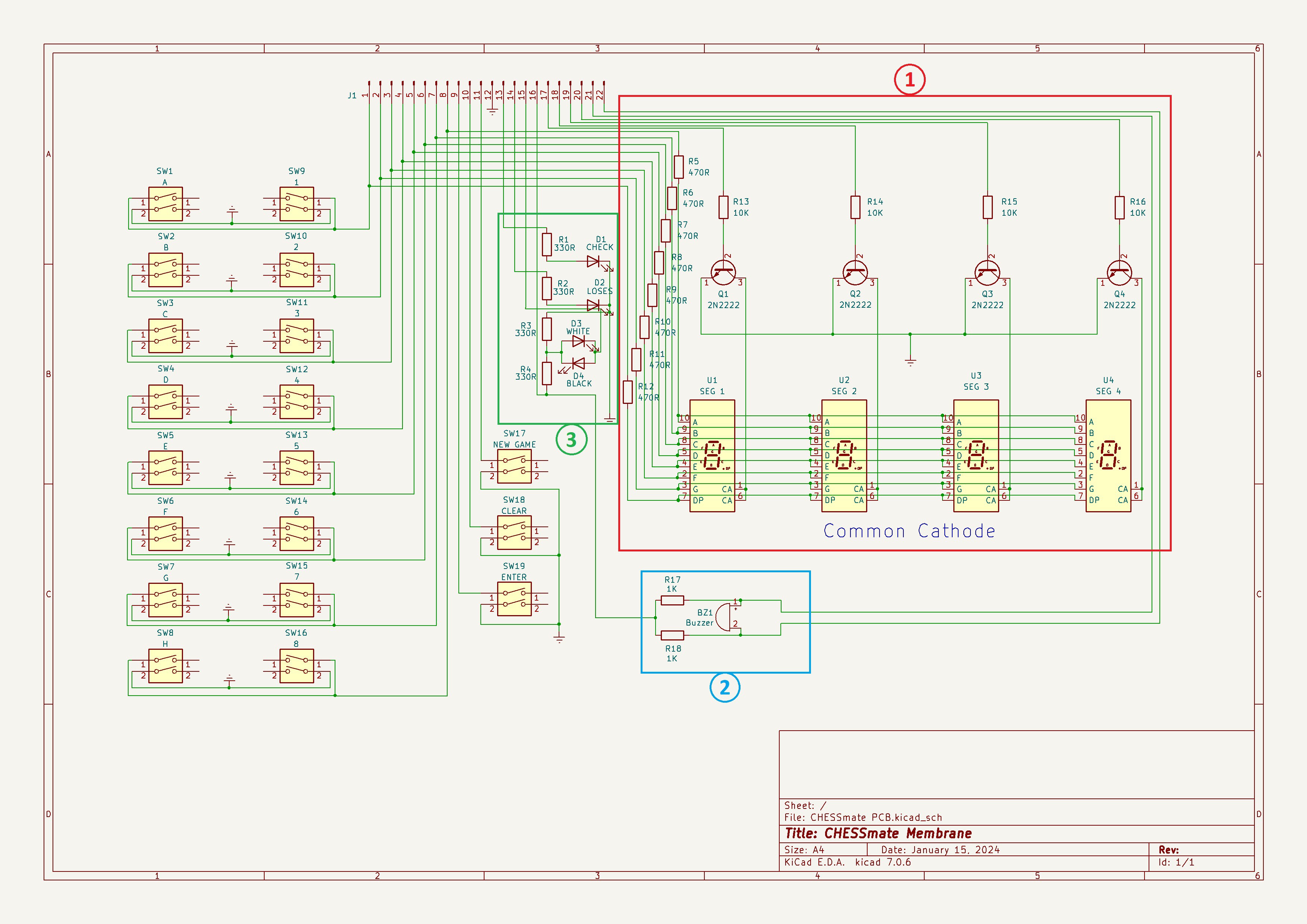
I was a bit perplexed by piezo buzzer circuit (2 above). Why use two IO pins when one will do? One of my makerspace (Kwartzlab) mates pointed out that the circuit reminded them of a full bridge motor controller. Sure enough further research revealed the magic of a full bridge piezo driver.
From the adafruit forum:
If you connect the Piezo between two of the Arduino's pins and control them so one goes high the same time the other goes low, you'll get what's called 'bridged' drive. That effectively doubles the voltage across the piezo element, making it louder.
Works a treat.
In order to free up a pin that I needed to get me to the 20-pin limit that the Arduino Pro Mini I will be using provides, I put the "Plays White" and "Plays Black" LEDs on a single pin (3 above) since they will always be the inverse of each other anyway (as does the original CHESSmate). I wanted to make sure that the circuit works and that the brightness of the two LEDs remains even.
I breadboarded these circuits and wrote a small quick and dirty sketch to exercise them.
void setup()
{
  // define pin modes

 pinMode(2,OUTPUT);  // 7-segment data
 pinMode(3,OUTPUT);
 pinMode(4,OUTPUT);
 pinMode(5,OUTPUT);
 pinMode(6,OUTPUT);
 pinMode(7,OUTPUT);
 pinMode(8,OUTPUT);
 pinMode(9,OUTPUT);
 pinMode(10,OUTPUT);  // 7-segment select
 pinMode(16,OUTPUT);  // // white / black LEDs
 pinMode(15,OUTPUT);  // Buzzer pins
 pinMode(14,OUTPUT);

 digitalWrite(16,HIGH);
}

void loop()
{
  // loop to turn display segments ON one at a time
  digitalWrite(10,HIGH);
  for(int i=2;i<10;i++)
  {
    digitalWrite(i,HIGH);
    delay(600);
  }

  // loop to blink display and alternate LEDs
  for(int i=0; i<10; i++)
  {
    if (i%2) {
      digitalWrite(10,HIGH);
      digitalWrite(16,LOW);
    } else {
      digitalWrite(10,LOW);
      digitalWrite(16,HIGH);
    }
   delay(600);
  }


  // Make a tone manually. Half Bridge.
  for(int i=0; i<1000; i++)
  {
      digitalWrite(14, LOW);
      // digitalWrite(15, HIGH);
      delay(1);
      digitalWrite(14, HIGH);
      // digitalWrite(15, LOW);
      delay(1);
  }
  delay(500);

  // Make a tone manually. Full Bridge.
  for(int i=0; i<1000; i++)
  {
      digitalWrite(14, LOW);
      digitalWrite(15, HIGH);
      delay(1);
      digitalWrite(14, HIGH);
      digitalWrite(15, LOW);
      delay(1);
  }

  // loop to turn display segments OFF
  for(int i=2;i<10;i++)
  {
    digitalWrite(i,LOW);
  }
}
Here is what running the test looks like.
The 7-segment display works as expected and is plenty bright. White and black LEDs alternate correctly and appear to be of even brightness. The first tone at the end is the piezo being run with only one output (half bridge) and the second tone with two outputs (full bridge) and is noticeably louder.
With these tests under my belt I sent the PCB off to be fabricated.
Discussions
Become a Hackaday.io Member
Create an account to leave a comment. Already have an account? Log In.