0%
0%
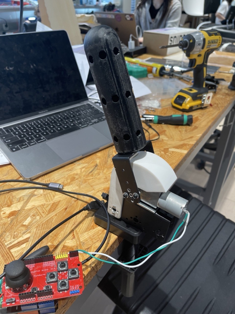
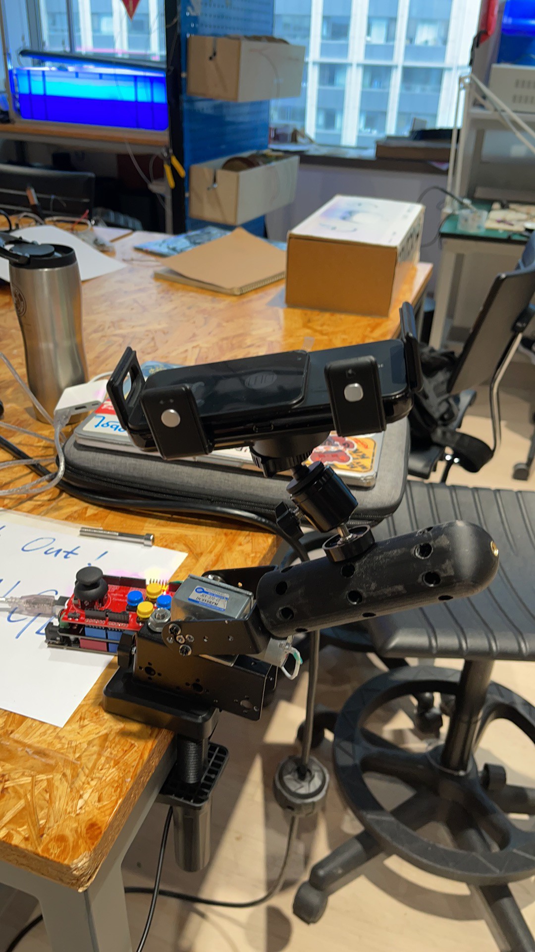
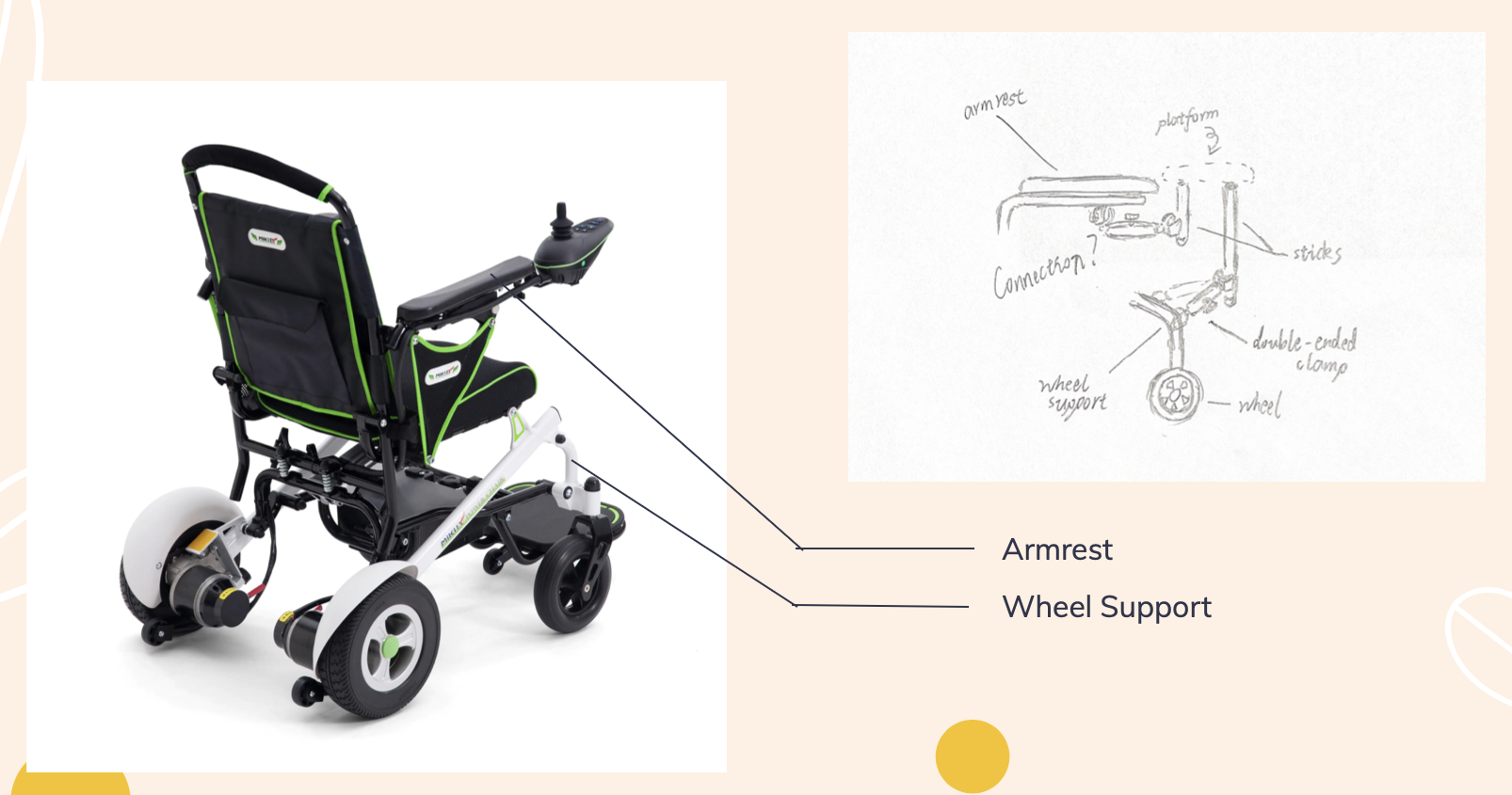
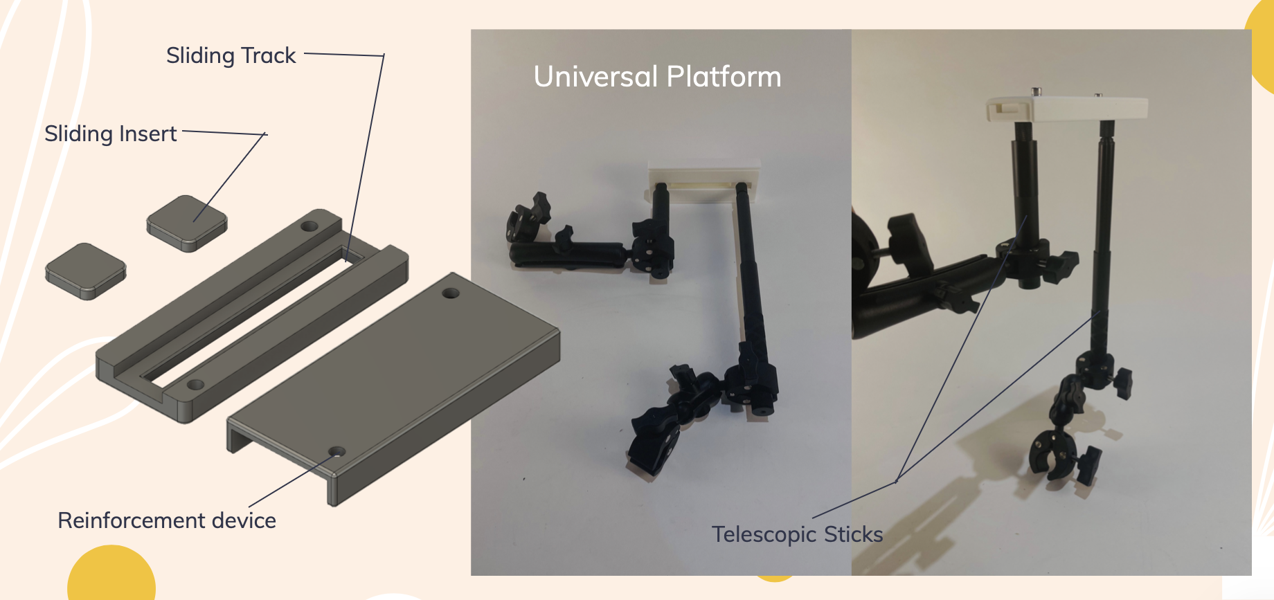
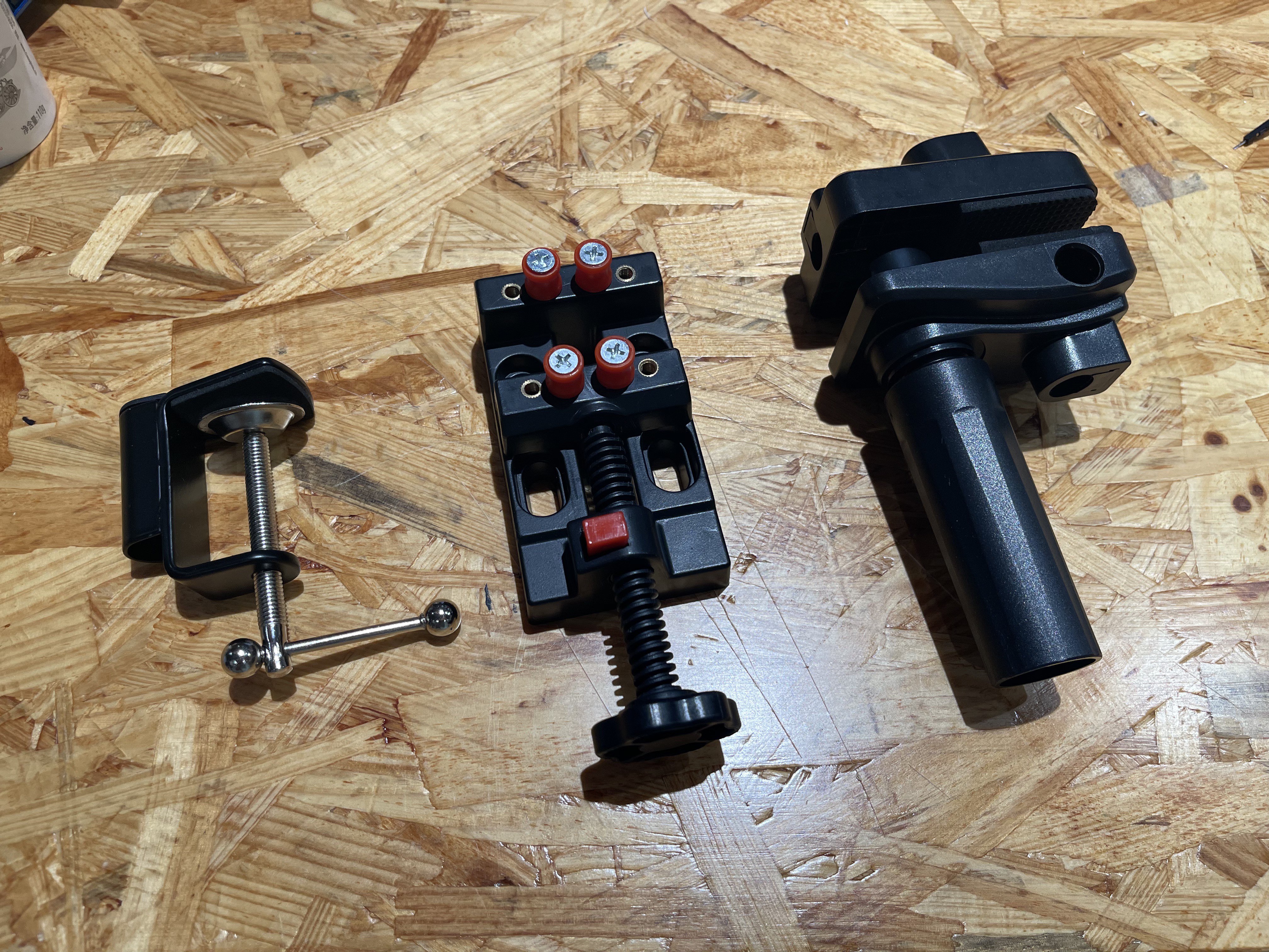
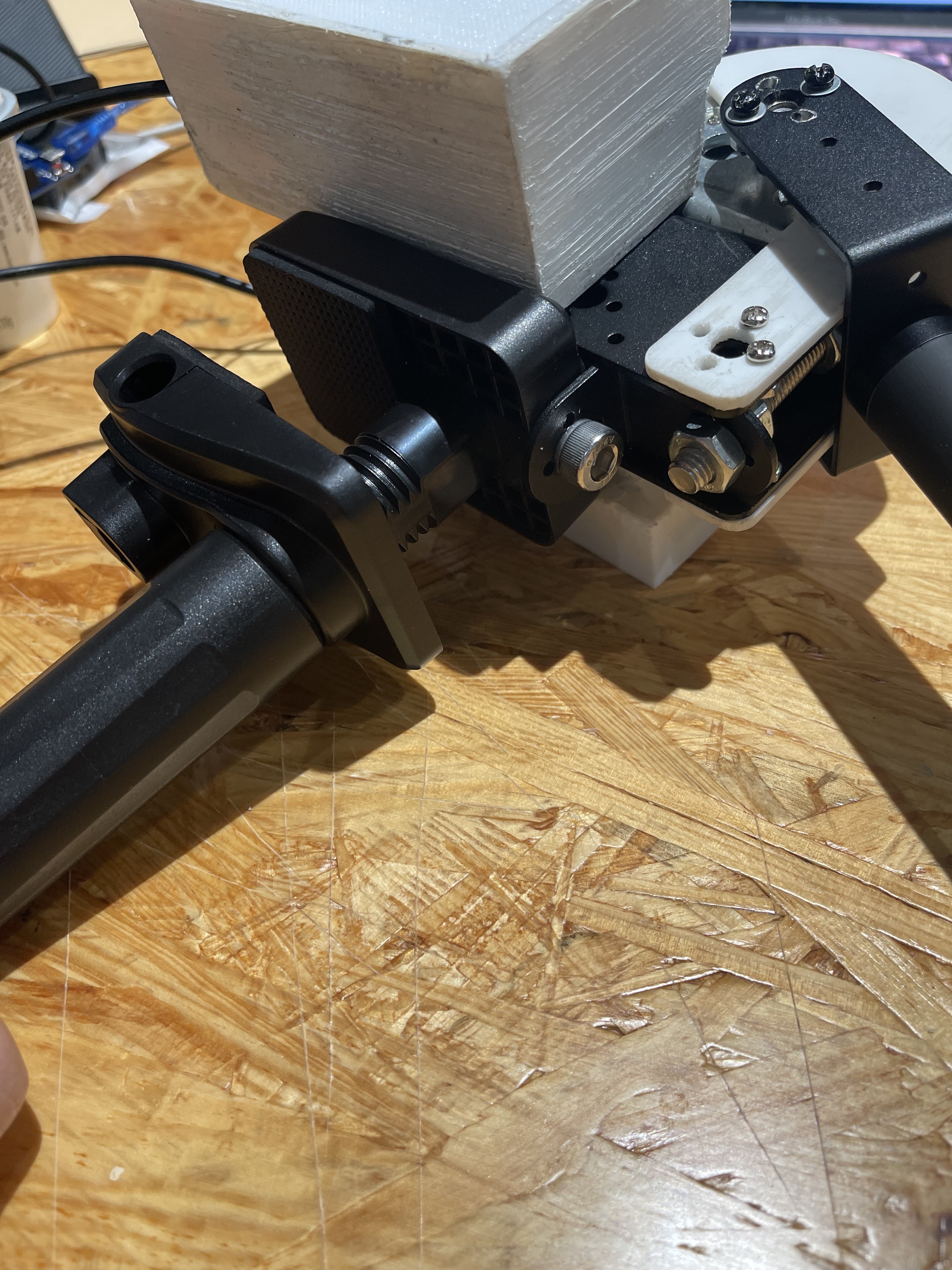
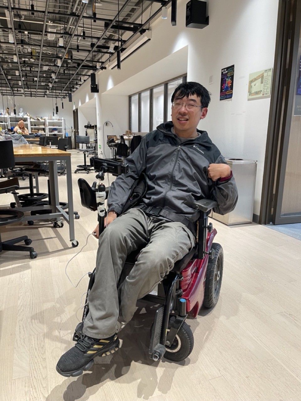
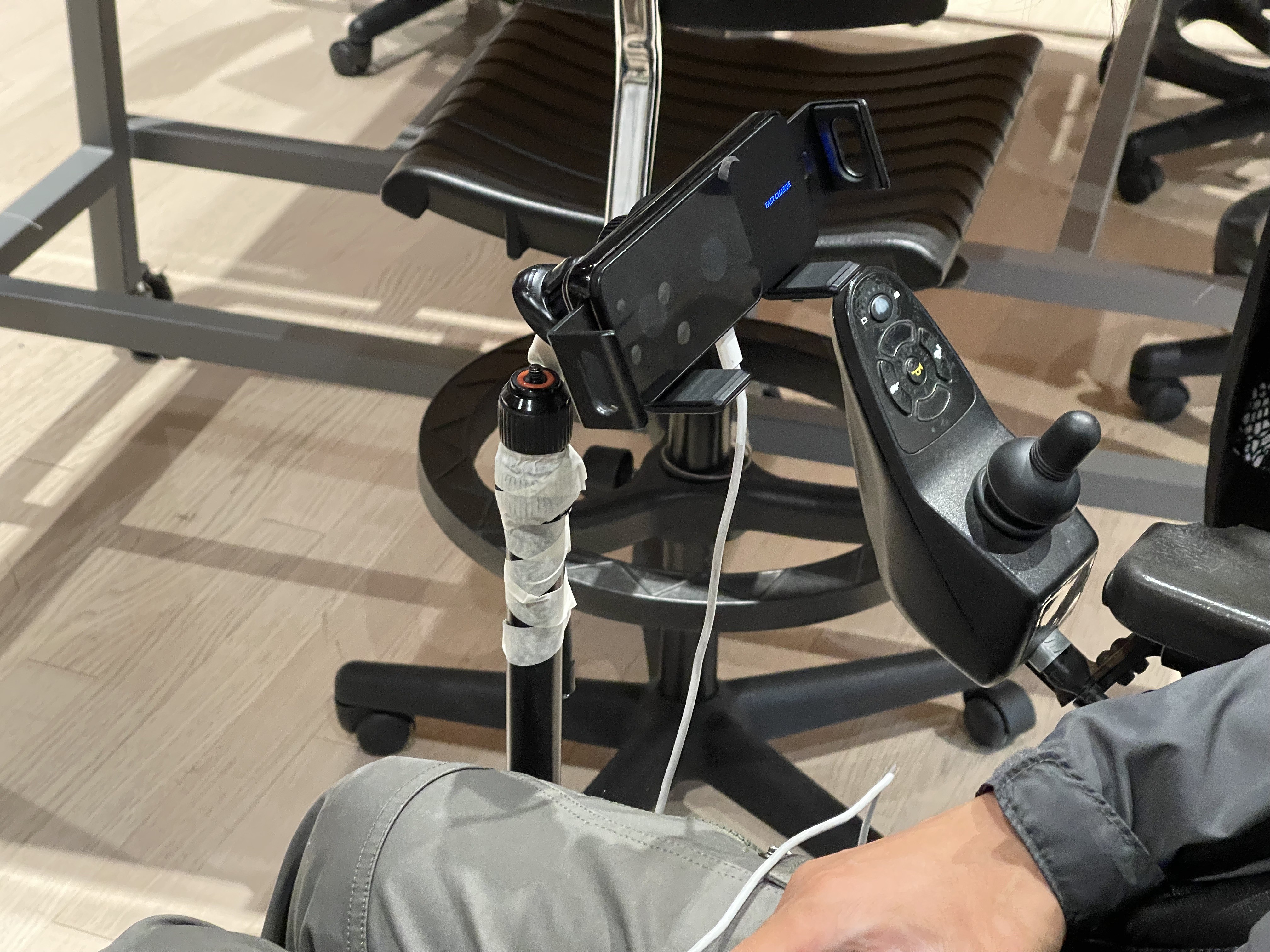
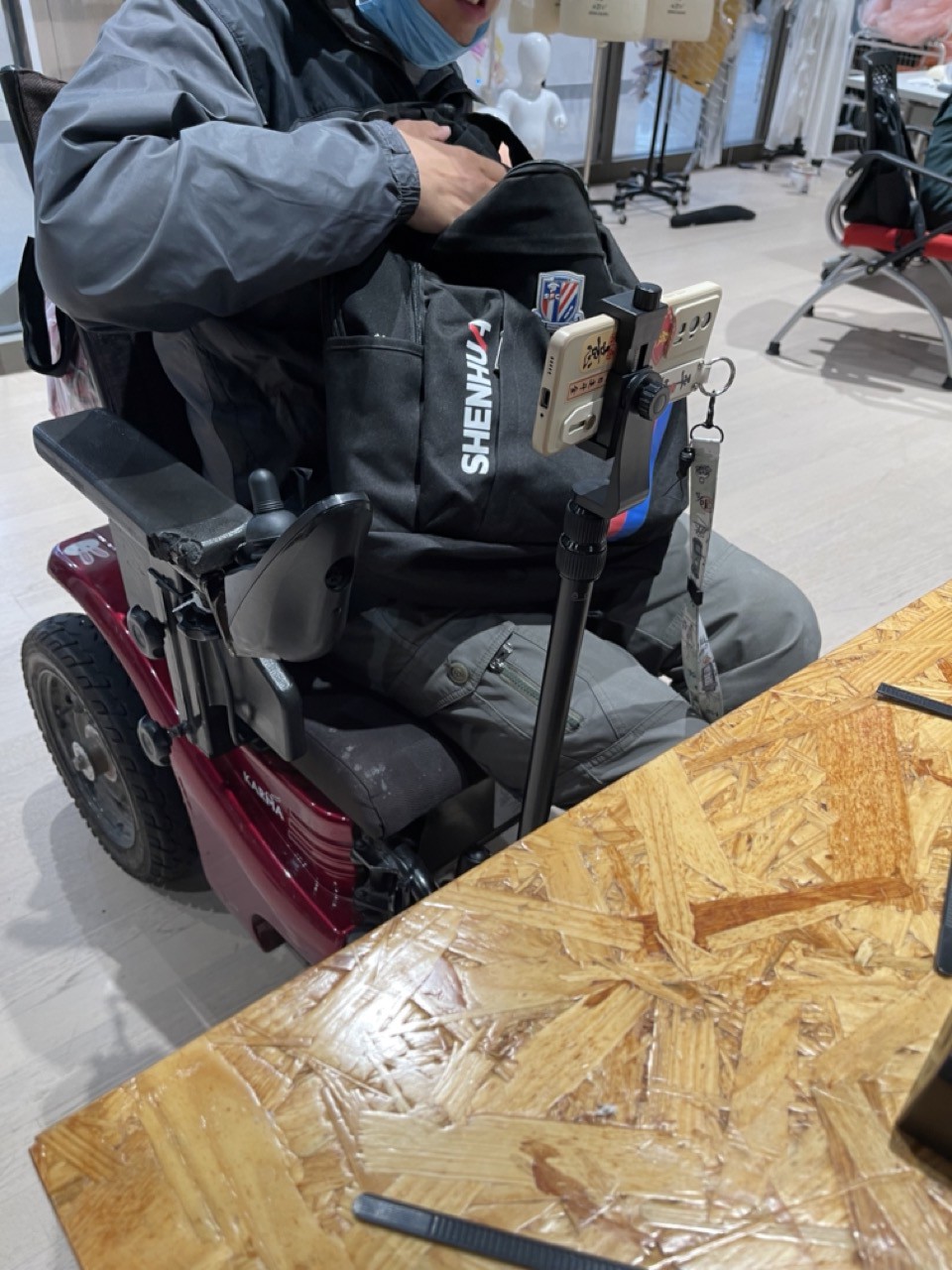
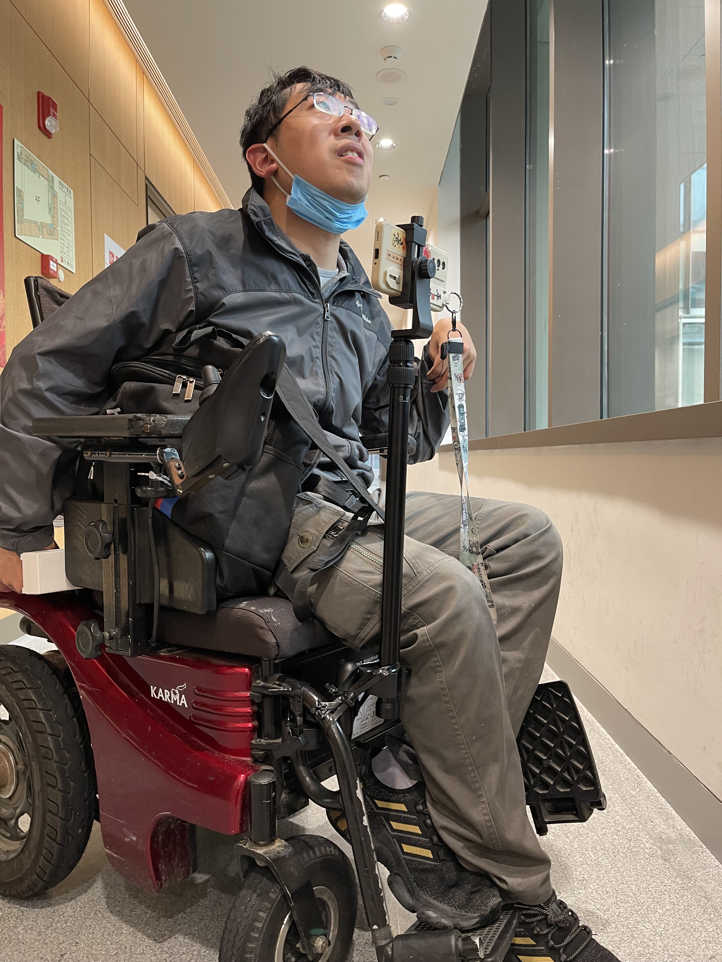
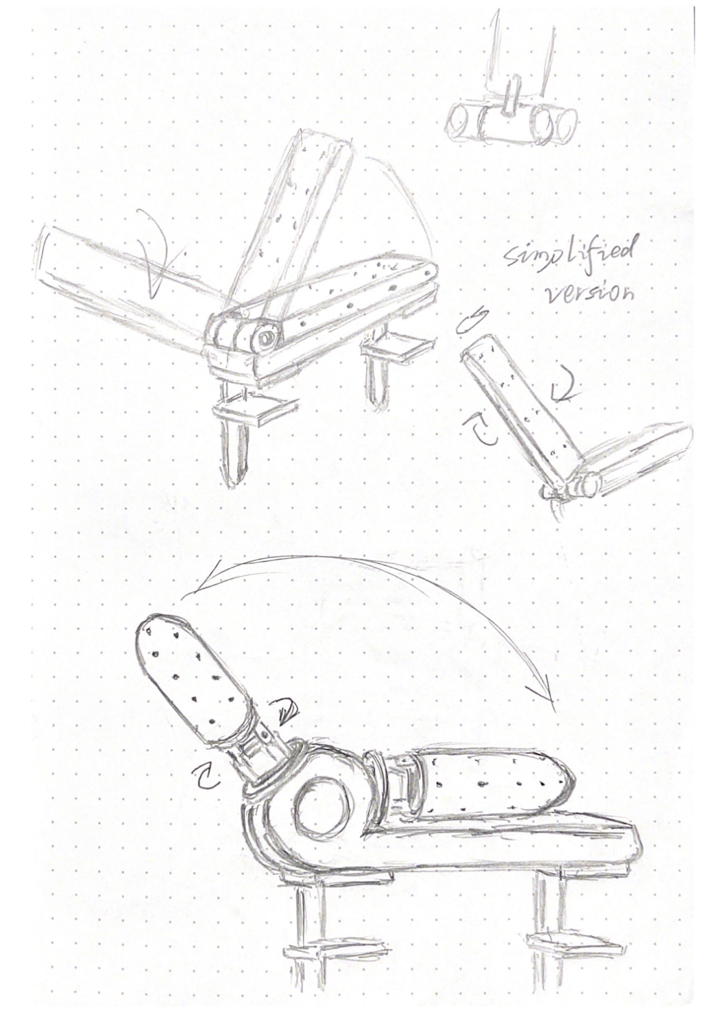
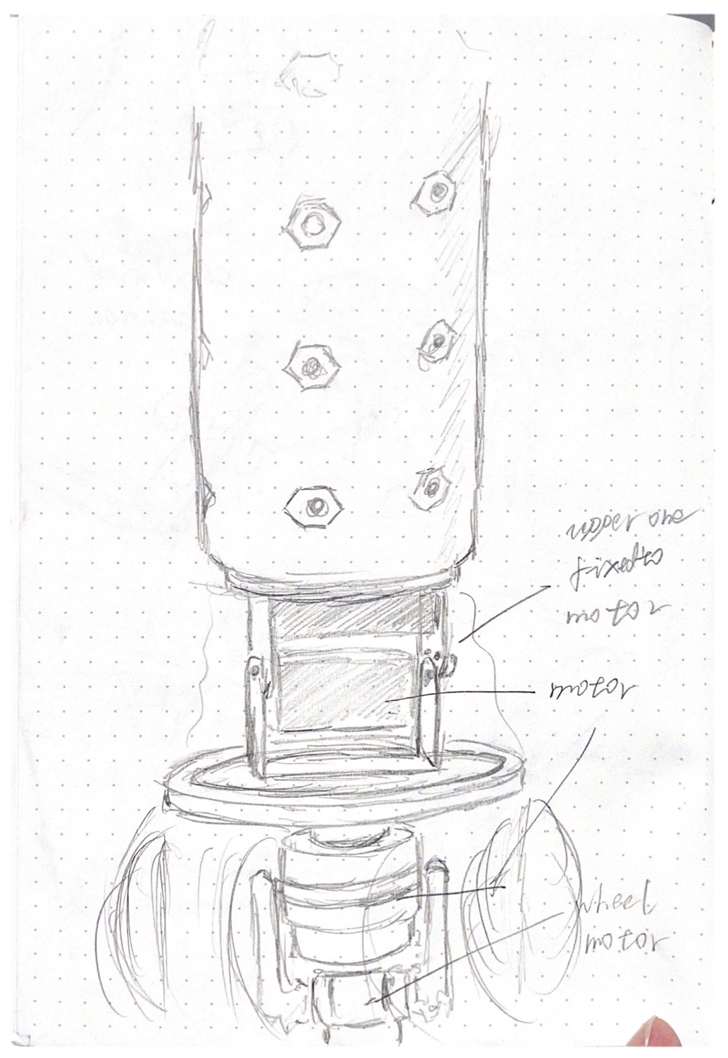
Creating AT for PRM: AnyAdapter (万接站)
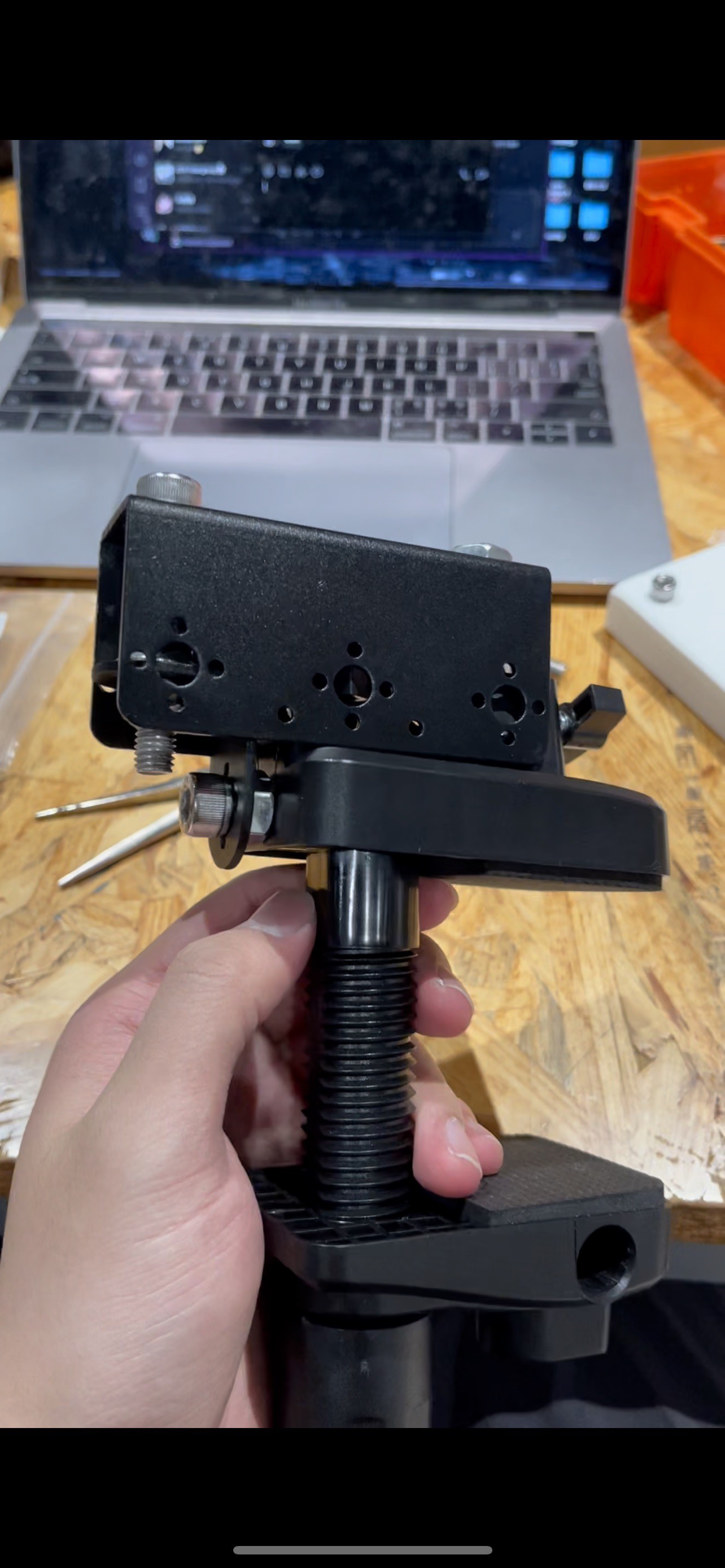
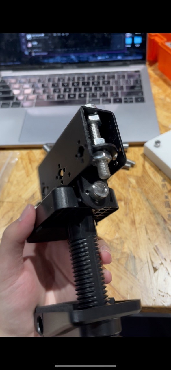
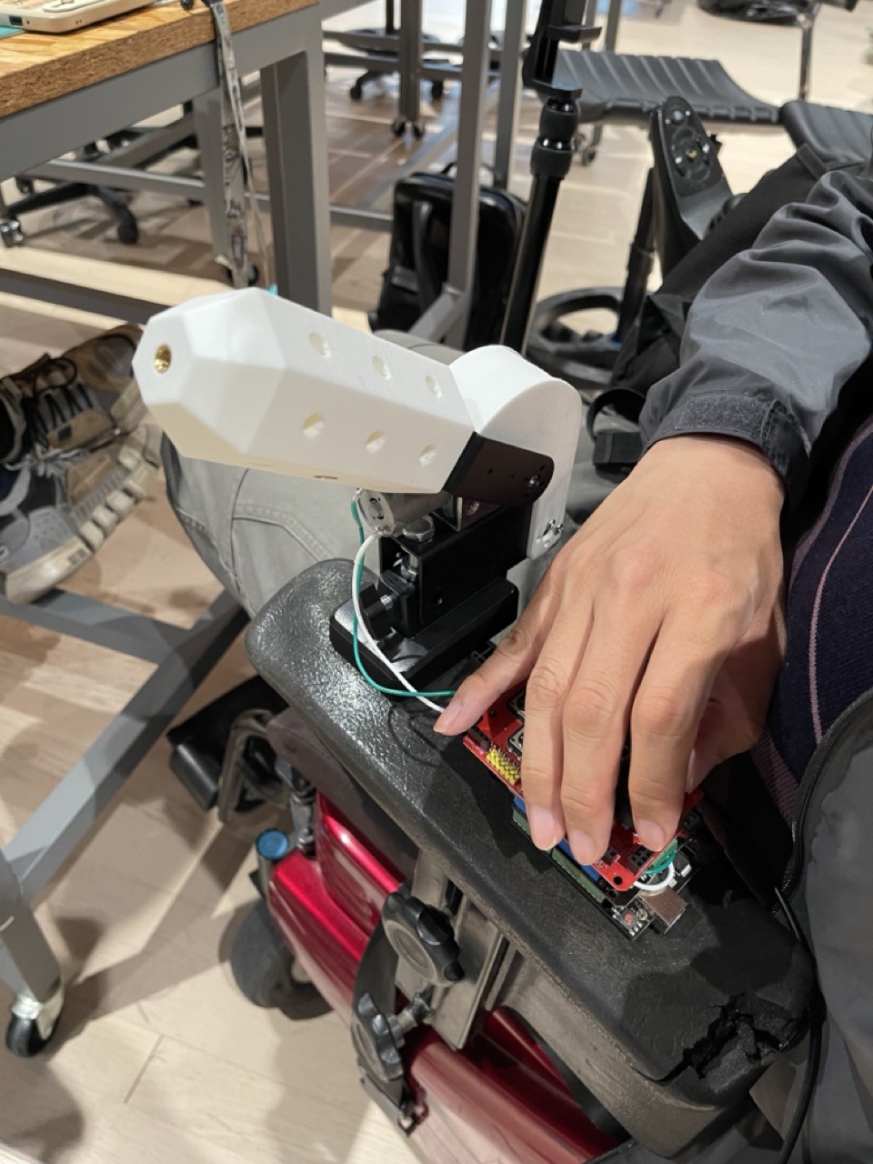
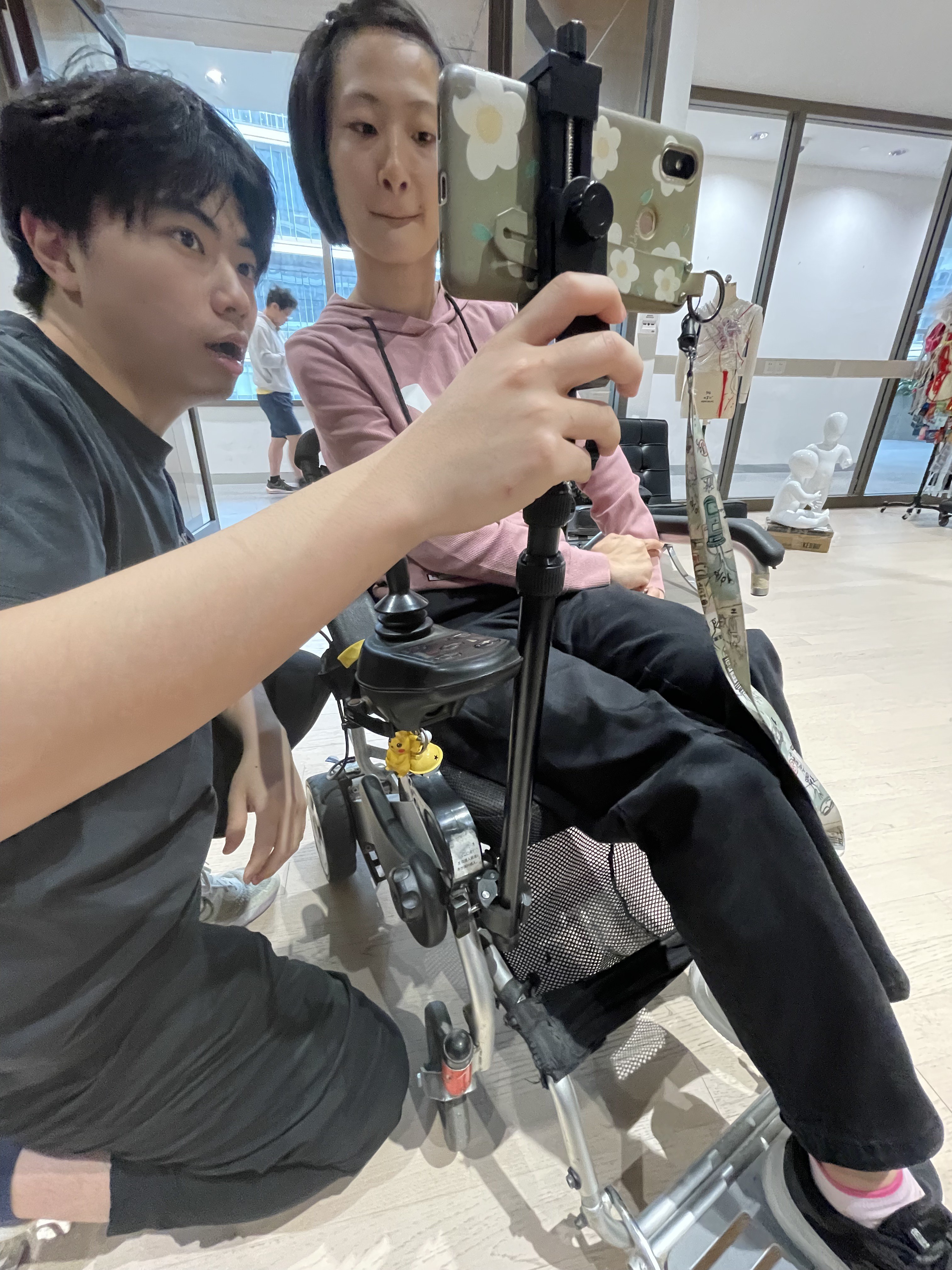
Multifunctional retainer attachment platform designed for wheelchair users.
 Junzhe Guo (Sebastian)
Become a Hackaday.io member
Already have an account? Log in.
Just one more thing
To make the experience fit your profile, pick a username and tell us what interests you.
Pick an awesome username
hackaday.io/
Your profile's URL: hackaday.io/username. Max 25 alphanumeric characters.
Pick a few interests
Projects that share your interests
People that share your interests

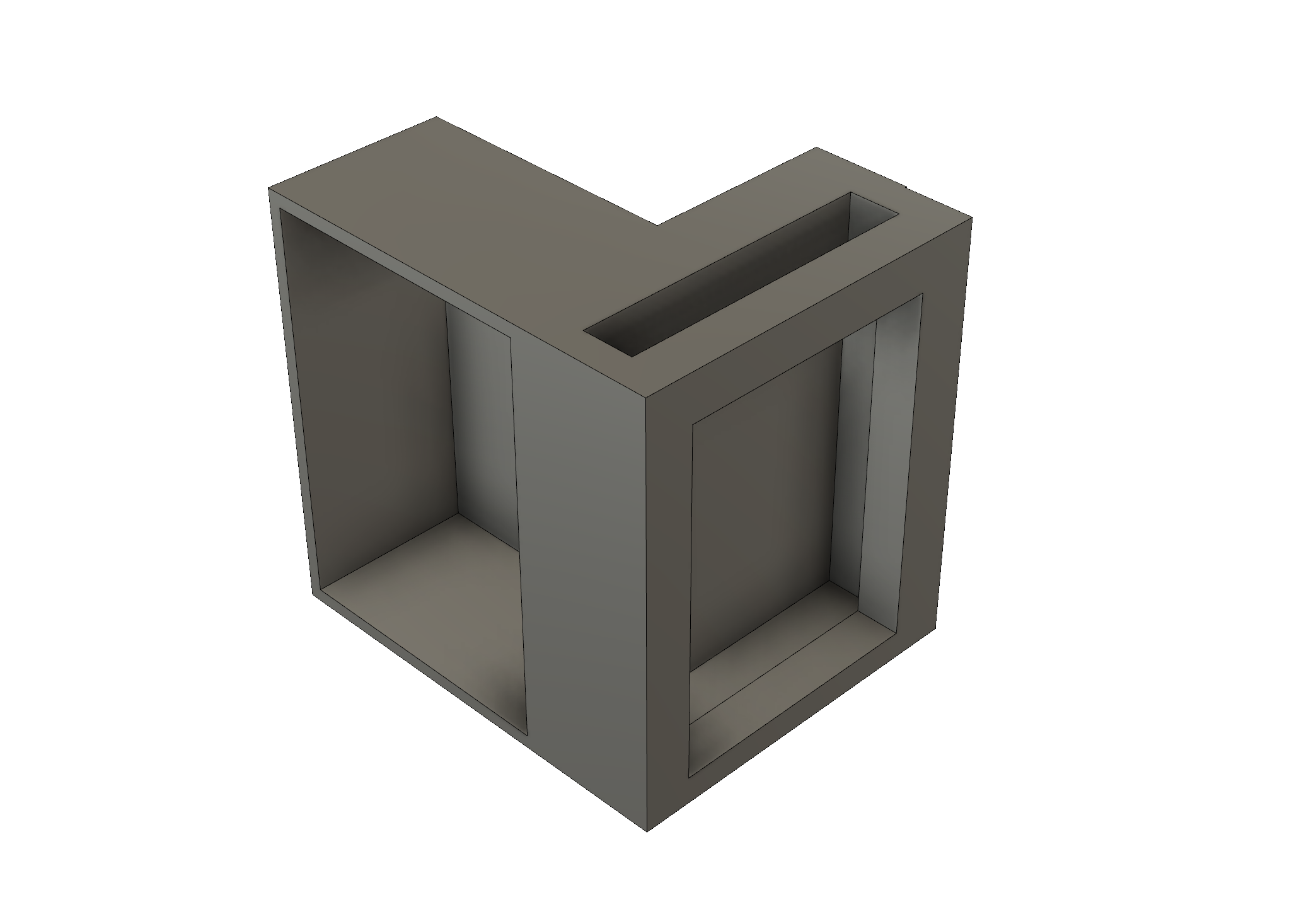
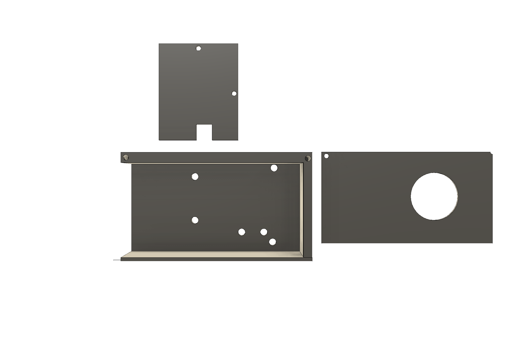
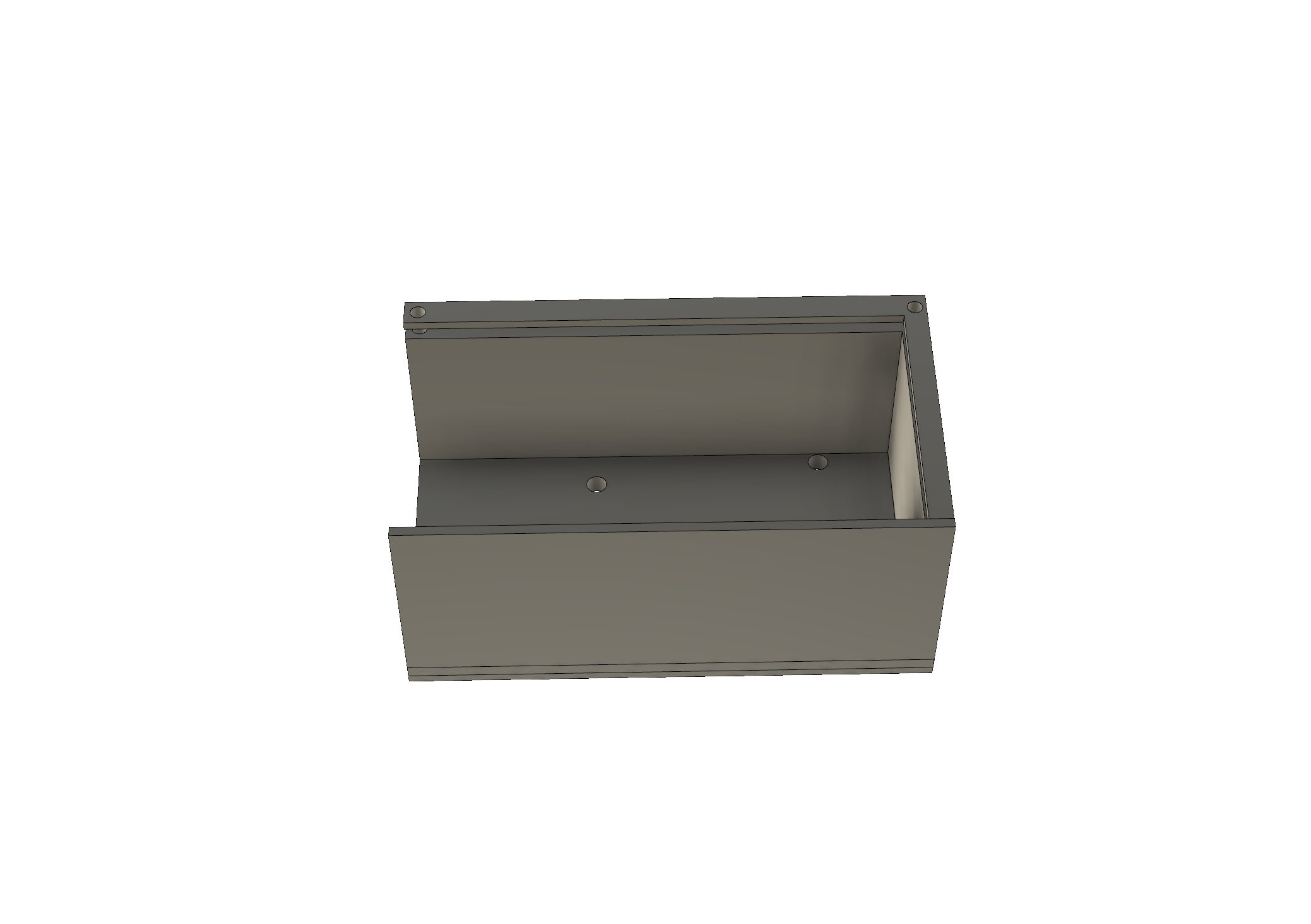
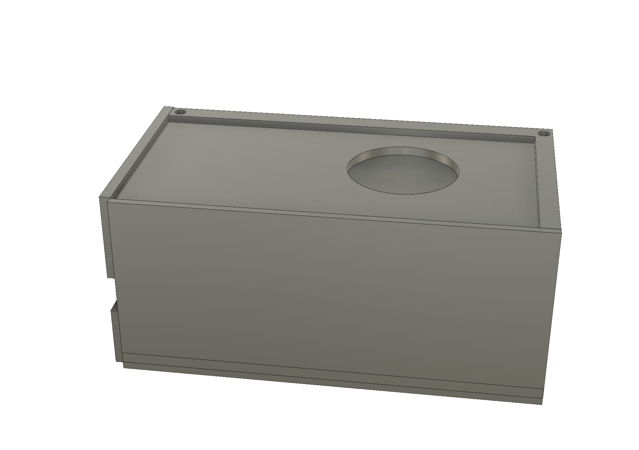
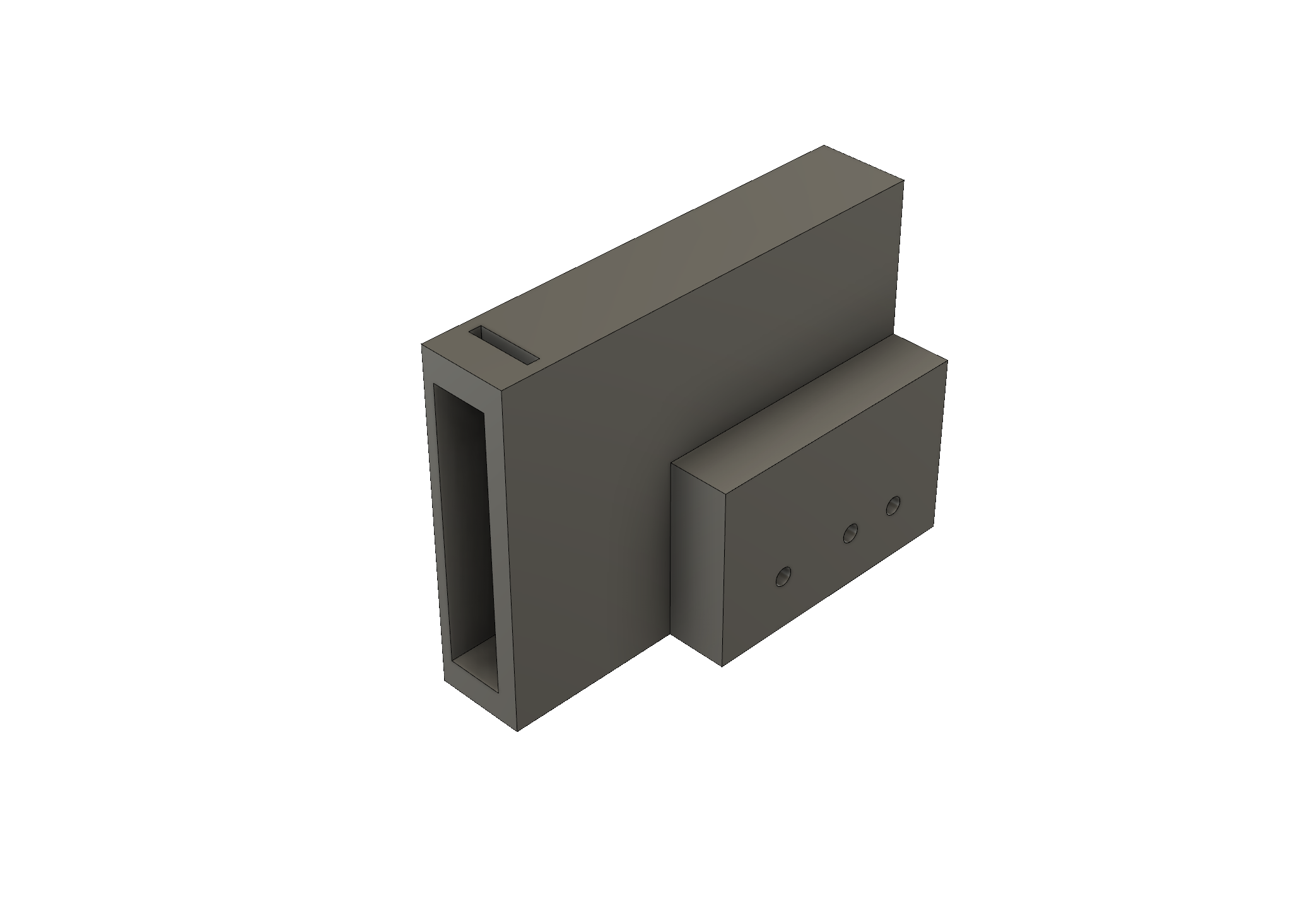
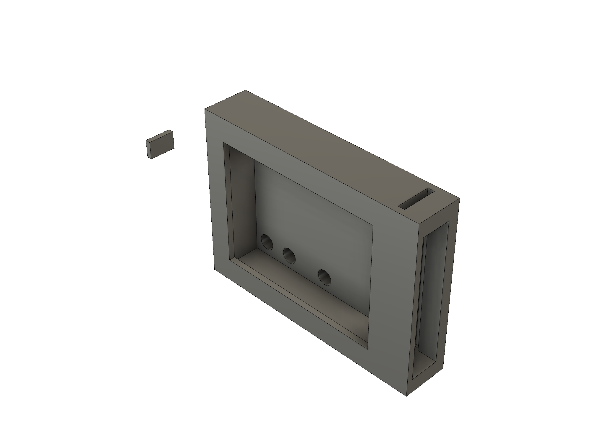
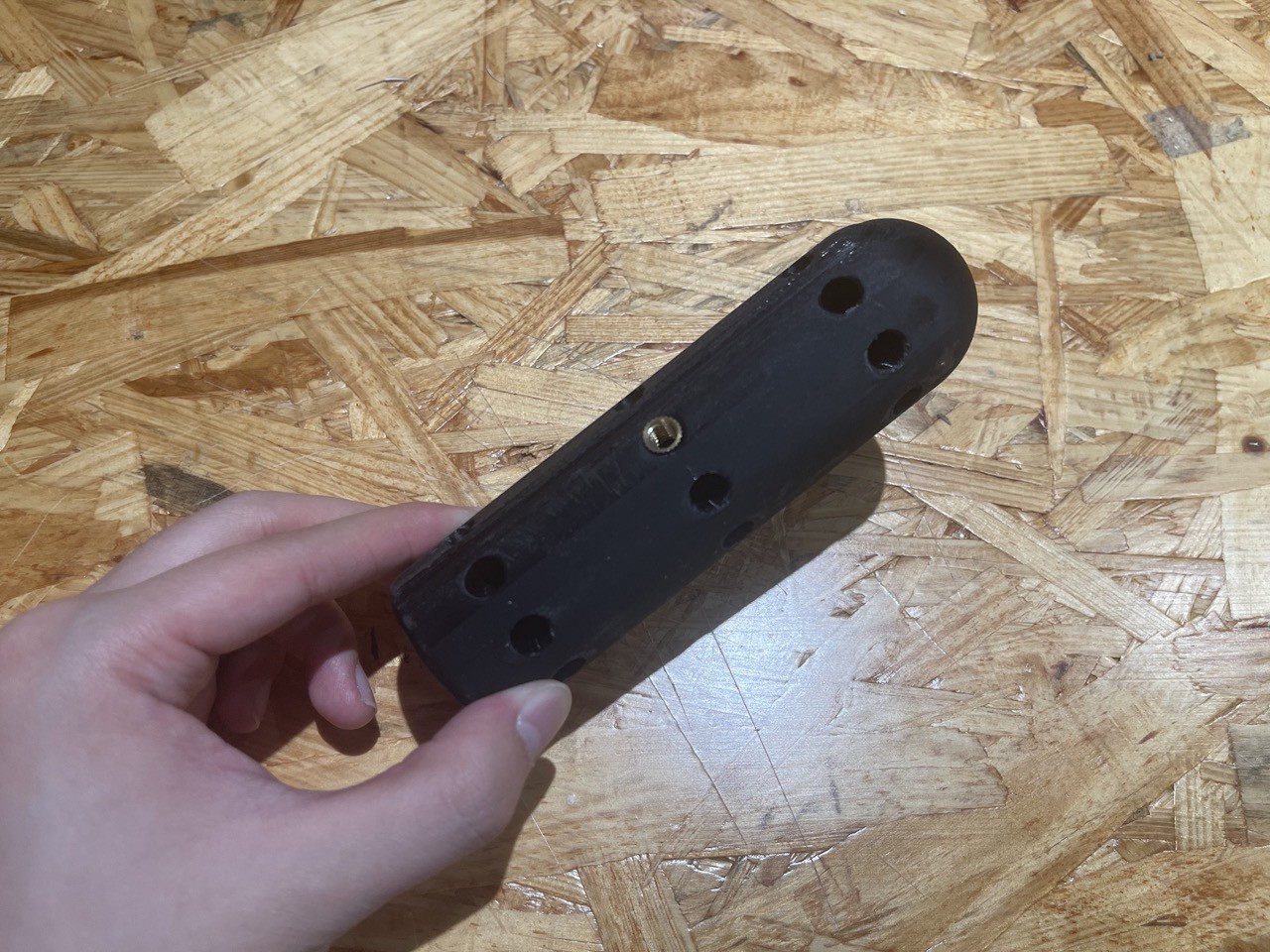
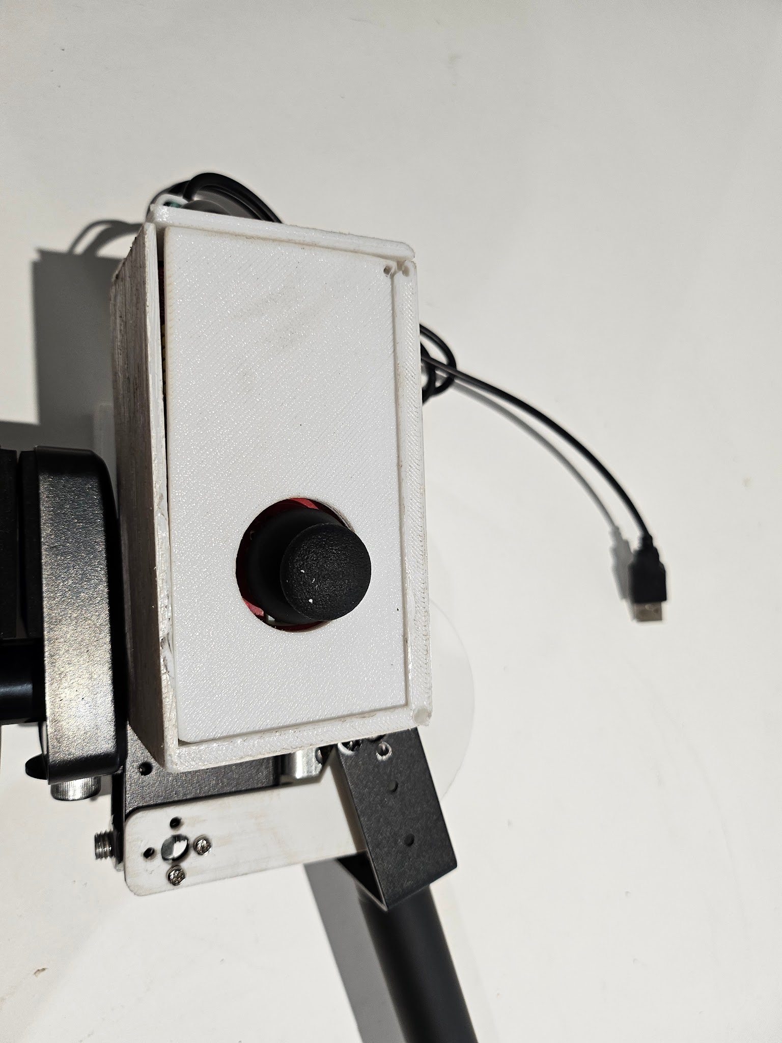 No modifications were made to the design, but in the future, I would consider incorporating a feature to completely conceal the wires from the user within this case.
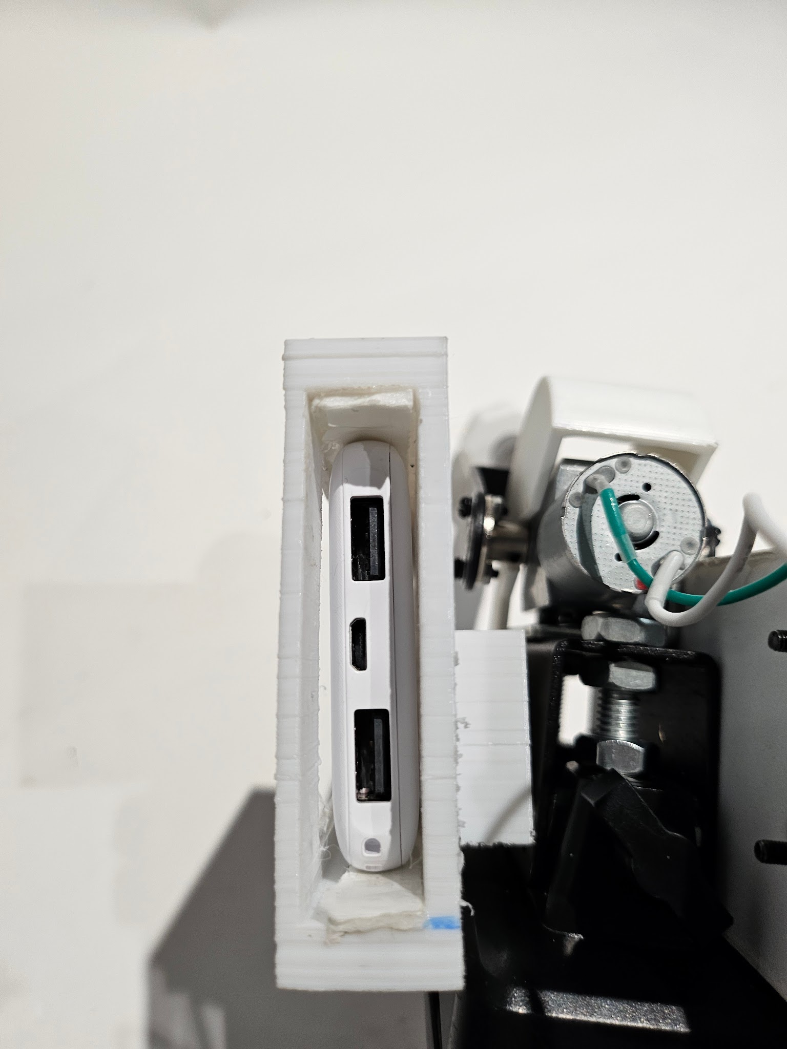


 TAIBHSE DESIGNS
 Shushanik Khachaturian
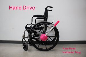
 Kate Reed
 Joseph Prosnitz