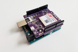
This project is an Arduino Uno R3 Shield using SPI to communicate with an sx1280 modem, a 2.4GHz Lora Module. This sx1280 sits atop the DLP-RFS1280 module, from DLP-Design.
I have a project that involves long range, low power communication, which a Lora device is a very good option for. Most current Lora devices operate on 433MHz, 868MHz, or 951MHz, so I was in trouble if I go outside of the region that my Lora Radio's frequency is license-less in. So I decided to make it easier by using the 2.4GHz spectrum which is available around the world and shared with Bluetooth and WiFi.
I wanted to create a device that allows me to text friends while backpacking and skiing. I chose the DLP-RFS1280 so I can add a larger antenna since it has a U.Fl connector. It's easily integrated into a project's PCB and it's FCC approved so it should be safe.
Begin by soldering the male header pins to the DLP-RFS1280 on a breadboard. Then Solder the DLP-RFS1280 to the PCB. Lastly the female header pins to the PCB. I've found if the PCB is resting on the DLP-RFS1280 and female header pins the soldering is easier.
2
Software
Open the Arduino IDE. Open the library manager to download the "sx1280OverSpi" library. Go to File > Examples > sx1280OverSpi > arduinoSendAndReceive to open the program for running the Lora Shield. Verify and upload to an Arduino.
3
Running
Open the serial monitor. Make sure you have the right baud rate. You should see a continuous print out. It will say what the DLP-RFS1280 is busy doing, the message being output, and the incoming message. Messages may be up to 255 characters so printing it may be very long.