 Bhavesh Kakwani
CircuitMaker project: https://circuitmaker.com/Projects/Details/Bhavesh-Kakwani-3/GLOVER-Rev-0
The electronics design is published under a Creative Commons "Attribution-NoDerivs / CC BY-ND" license.
Tactical glove for military stealth communications using hand signals
Already have an account? Log in.
To make the experience fit your profile, pick a username and tell us what interests you.
CircuitMaker project: https://circuitmaker.com/Projects/Details/Bhavesh-Kakwani-3/GLOVER-Rev-0
The electronics design is published under a Creative Commons "Attribution-NoDerivs / CC BY-ND" license.
BOM_PartType-GLOVER Rev 0 - SeeedStudio.xlsBOM for SMD components on PCB Rev 0 (I will update it soon with the through hole connectors as well)ms-excel - 32.50 kB - 11/18/2017 at 16:51 |
|
|
nRF52832_PS_v1.1_Datasheet.pdfnRF52 microcontroller datasheetAdobe Portable Document Format - 4.60 MB - 11/13/2017 at 23:20 |
|
|
BMD-300-Series-DS-V1.10.pdfRigado BMD-300 nRF52 module's datasheetAdobe Portable Document Format - 2.43 MB - 11/13/2017 at 23:19 |
|
|
PS-MPU-9250A-01-v1.1.pdfMPU-9250 IMU's datasheetAdobe Portable Document Format - 939.94 kB - 11/13/2017 at 23:19 |
|
|
MCP73831 Datasheet.pdfMCP73831 LiPo charging module's datasheetAdobe Portable Document Format - 823.05 kB - 11/13/2017 at 23:19 |
|
|
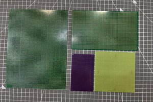
The PCBs have arrived from OSHpark! Thanks to them for sponsoring our first prototypes. Excited to reflow these as soon as possible. I'm currently cleaning up the BOM manually and deciding on which solder paste and syringe to order. Hopefully I can send in the Digikey order tomorrow. Check out the PCBs:
In some bad news, the PCB stencil I ordered from OSHstencil is gonna take a long indefinite time to arrive, because of the incredible inefficiency of USPS. Lesson learned: never use USPS for shipping! Seriously, the same thing happened to a university friend of mine a couple months ago too.
The full Rev 0 PCB Design is complete and gerbers have been sent to the manufacturer! We are manufacturing 3 prototype boards from the amazing OSHpark. It's a 2-layer board with all the components on one side.
In other good news, we got accepted into an incubator at the University of Toronto! More details to come soon, after signing some documents.
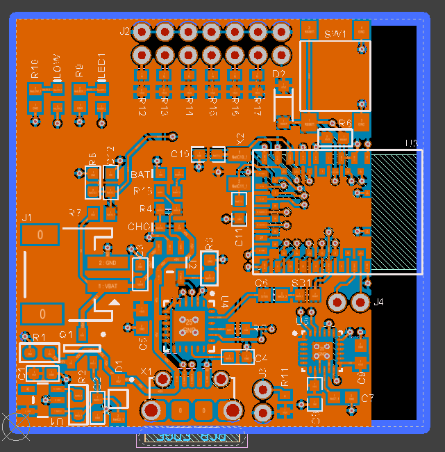
I should've created this Hackaday project page a long time ago...lots of progress has been made in the 1.5 months of working on this so far. The latest update is that the PCB schematics are complete and reviewed (thanks, Jimmy!) and the components have generally been placed in good spots on the PCB. Check out the 3D screenshot from our CircuitMaker project below!:
Let's hope it's not a pain to route it on a 2-layer board. Fingers crossed!

 And below is the 3D render for your viewing pleasure.
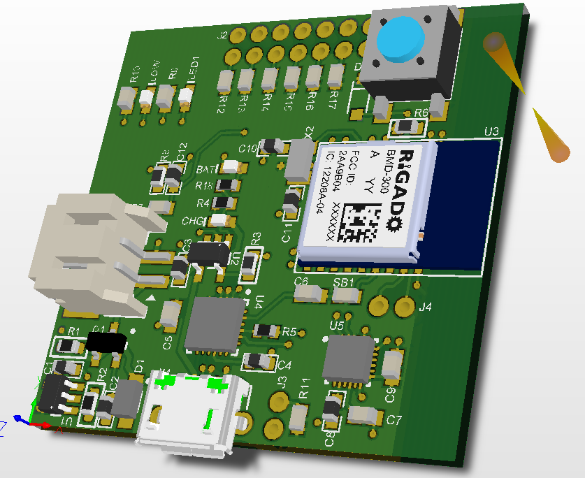 If you wanna check out the design, the board is called "GLOVER REV 0" in the CircuitMaker community. Don't ask me why they make all the project names all-caps :P
 ElectroBoy
 Lithium ION
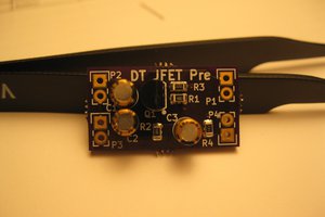
 AVR
AVR
 Michael Delaney