danjovic
-
Bugfix and findings
11/01/2015 at 17:52 • 0 commentsI have fixed a small bug that was making the slot to advance right after the device was inserted.
When the program enters the usbFunctionWrite() it compares the state of the LEDs against the last known state. If there is a change then one of the LOCK keys has been pressed and toggled its state.
The problem was related with the difference between the initialization value of LED_state variable with the first LED status reported (sent) by the host computer. The initialization LED_stat variable is 0xFF and the LED report is always 00000SCN being the 3 LSBits the state of SCROLL, CAPS and NUM lock. So the first compare, performed by a XOR would always result as a non zero. Then if the NUM LOCK was not set the XOR of its bit with the first state would always result in '1' and the slot was incremented.
The same occurred for CAPS LOCK, then the amount of taps on the CAPS Lock would vary from 4 to five.
The effect on SCROLL lock was hidden because up to now the password is being sent when the device is plugged in for the first time.
The bug fix was simple: The only time the LED_state variable is equal to 0xff is during the initialization (remember, the 5 MSBits from the LED report sent by the computer are always '0'), so the following statement solved the problem.if (LED_state == 0xff) LED_state = data [0];The whole function is shown belowusbMsgLen_t usbFunctionWrite(uint8_t * data, uchar len) { uint8_t changed; if (LED_state == 0xff) LED_state = data [0]; changed = data[0] ^ LED_state; if (!changed) return 1; else LED_state = data[0]; if (changed & CAPS_LOCK ) caps_toggle(); if (changed & SCROLL_LOCK ) { // scroll lock eeprom_read_block(messageBuffer, stored_password, sizeof(messageBuffer)); messagePtr = 0; messageState = STATE_SEND; } if (changed & NUM_LOCK ) { // advance slot, roll back at maximum if (slot < MAX_PASSWORD_SLOTS-1) slot++; else slot=0; } return 1; // Data read, not expecting more }Well, now about the finding... My laptop has a standard keyboard with no numeric keys. Well, I have found that the NUM LOCK function is processed locally, I mean, it happens on the keyboard level, not at operating system level. The effect is that NUM LOCK on my laptop and probably on other laptops won't be able do advance the slot. It is a pity but it is not a loss, because the operation using NUM LOCK / SCROLL LOCK is a redundancy. -
Button control: Working
10/31/2015 at 15:01 • 0 commentsI've managed to put both SELECT and SEND buttons to work by using a non-blocking de-bouncing routine than can even distinguish between 'short-press' and 'long-press'.
The algorithm is very simple
static int counter;

if (button_is_pressed)
    counter++;
else { // button is released
   if (counter < _time_short_press) return _no_key_pressed
   if (counter < _time_long_press) return _short_press
   /*else */ return _long_press
}
the real code is a bit more complex because you have to saturate the counter so it doesn't roll over, and at the release it has to be zeroed.
Another challenge was how to measure the correct timing for the temporization of short press (~100ms) and long press (500ms). Initially I have set the 'counter' variable to uint_16 and tried to guess the correct values but ,since the debounce routines run in the main loop, even a large value like 65500 counts were reached withing the time of a short press.
The solution was another trick involving TIMER2. We know from a previous log that TIMER2 increments at each 64us (16MHz/1024=15625Hz=1/64us). Using other words, the bit 0 from register TCNT2 flips at each 64us, then the bit 1 flips at each 128us, and so on.
Then if I consider again using a counter with 8 bits, and want to keep the long press time close to the end of counting, I can assume that 250 countings will be equal 500ms. Doing the math, a short press shall take at least 50 counts (100ms) and ONE count shall be as close as possible to 2ms.
Well, 2ms/64us is pretty close to 32 and now the problem is solved: The debouncing routine shall check if the 5th bit of TCNT 2 has flipped since the last time it was called. If so and the button is pressed, then increment the counter.The whole code for 1 button is shown below
#define B1_Pressed ((PINB & (1<<1))==0) #define treshold_short_press 50 #define treshold_long_press 250 uint8_t debounce_B1 (void) { static uint8_t last_timer_toggle=0; static uint8_t time_button_pressed=0; uint8_t temp; if (B1_Pressed) { temp=TCNT2 & (1<<5); // if ( (temp!=last_timer_toggle) & (time_button_pressed <255) ) {// advance and saturate VX7333b6450X time_button_pressed++; last_timer_toggle=temp; } return _no_press; } else { // button is released temp=time_button_pressed; time_button_pressed=0; if (temp < treshold_short_press) return _no_press; //below noise treshold if (temp < treshold_long_press) return _short_press; //above noise treshold and below long press treshold else return _long_press ; //above long press treshold } return _no_press; // redundant } -
Contest Entry Checklist
10/31/2015 at 09:59 • 0 commentsBased on the contest rules I've created a checklist to be printed and left in plain sight in my benchtop, so I can easily see what's left to be done as well as the deadlines. This will help me to not get disqualified by forgetting small things like fulfilling the BOM.
Checklist is available inOpenOffice format and in PDF
![]()
-
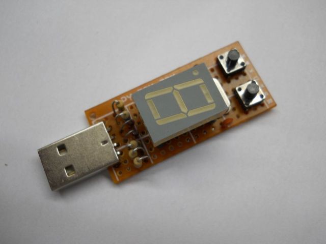
7 segment display: Working!
10/30/2015 at 03:22 • 0 commentsThe 7 segment display is now working. The display routine uses 3 most significant bits from Timer2 to select which segment to refresh. Taking the 16MHz crystal and using a prescaler of 1024 we have the following timings for each bit of Timer Counter 2:
TCNT2 =   7 6 5 4 3 2 1 0
          | | | | | | | |
          | | | | | | | +---  = 16.000.000/1014 = 15525   Hz
          | | | | | | +-----  = 15625 / 2       = 17812,5 Hz
          | | | | | +-------  = ~3906 Hz
          | | | | +---------  = ~1953 Hz
          | | | +-----------  =  ~976 Hz
          | | |
          +---+-------------  =  ~488 Hz
The 3 most significant bits from TCNT2 flips at a frequency of about 488Hz. Then, by using this 3 bits as an address for each segment of the display, I have a refresh rate of approximately 488/8 = 61Hz, and all segments will stay ON for the same amount of time, without having to worry about measuring time in code. I simply call a refresh_display( ) function with the segments that shall be on as an argument.
void refresh_display( uint8_t segments) {

    uint8_t segment_now = (TCNT2 >> 5);

	// turn on/off segment according with state of digit
	switch (segment_now) {
	case _A:   if (segments & (1<<_A) )  _A_ON; else _A_OFF;
		break;
	case _B:   if (segments & (1<<_B) )  _B_ON; else _B_OFF;
		break;
	case _C:   if (segments & (1<<_C) )  _C_ON; else _C_OFF;
		break;
	case _D:   if (segments & (1<<_D) )  _D_ON; else _D_OFF;
		break;
	case _E:   if (segments & (1<<_E) )  _E_ON; else _E_OFF;
		break;
	case _F:   if (segments & (1<<_F) )  _F_ON; else _F_OFF;
		break;
	case _G:   if (segments & (1<<_G) )  _G_ON; else _G_OFF;
		break;
	case _DP:  if (segments & (1<<_DP) )  _DP_ON; else _DP_OFF;
		break;
	}
}
The macros _A_ON / _A_OFF and so on simply set or reset one bit from one port. This makes my life easy, since not all bits from the display share the same port. Indeed, the bits are spread across ports B, C, and D for making the PCB layout easier.
The results can be seen in the video below. I am using NUM LOCK for advancing the slot.
-
A way to upload legacy passwords to the device
10/28/2015 at 13:35 • 0 commentsI am still wondering about how to upload legacy passwords to the device.
Initially I've considered using a bootloader, and that would also allow me to update the firmware, but this approach has its drawbacks: It requires installing libusb drivers and avrdude prior to the the first use.
Then I thought on an alternative solution: Use the LED states (lit/unlit) as clock and data lines, for instance:
NUM LOCK - DATA 0
CAPS LOCK - DATA 1
SCROLL LOCK - CLOCK
Then at every change on SCROLL LOCK I could sample 2 bits of data. Doing the math, for 16 passwords of 12 characters with a 6 bit wide character set I would need 16 * 12 * 6 = 1152 bits or 576 state changes. If I could do 20 changes per second (it's a guess) then it would take me half a minute to upload all the passwords.
Not bad!
-
BOM: Part Numbers
10/28/2015 at 00:33 • 0 commentsI've spent some time mining at Mouser website and compiled the bill of materials by manufacturer part number. I took care to choose items by availability and price.
Whole list with links to Mouser website available below, but the manufacturer part number makes easier to search for the same components in other electronics distributors (Farnell, Newark, Tarzan, etc)
Components / Part Numbers
- IC1 ATMega8-16AU
- DS1 SC56-11GWA
- D1,D2 ZMM5226B
- C1 12065C104KAT2A
- C2,C3 VJ0805A220JXGAT5Z
- R1 CRCW08052K20FKEA
- R2,R3 CRCW080568R0FKEA
- R4 CRCW080510K0FKEA
- R5 CRCW0805470RFKEA
- XT1 HCM49-16.000MABJ-UT
- S1,S2 B3F-3122
- K1 48037-0001
-
Use of buttons
10/27/2015 at 03:38 • 3 commentsI've been considering about removing both buttons and using [NUM LOCK] and [SCROLL LOCK] for changing the slot and sending the password, respectively. In this case a hidden reset button would place the microcontroller in bootloader mode.
On the other hand, without buttons I would not be able to use the Key Pass in devices without keyboard, like tablets and phones.
Maybe the best solution for now is to allow the change of slot by either pressing [select] button or [Num lock] on the keyboard, and sending (typing) the password either by [send] button or by [Scroll Lock] key.
-
Bootloader up and running
10/27/2015 at 03:25 • 0 commentsIn order to ease the development I've added the USBaspLoader to the project. The bootloader is activated by pressing and holding both buttons while the board is inserted in the USB slot (i.e. when the board is powered).
Using the Bootloader I've uplodaded the firmware from the inspiring project , ported to ATMega8.
I will probably keep the bootloader since it allows me to upload pre defined passwords to the EEPROM space of the microcontroller which is necessary to support legacy passwords.
-
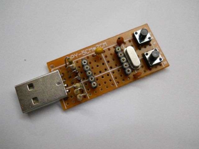
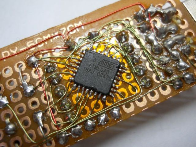
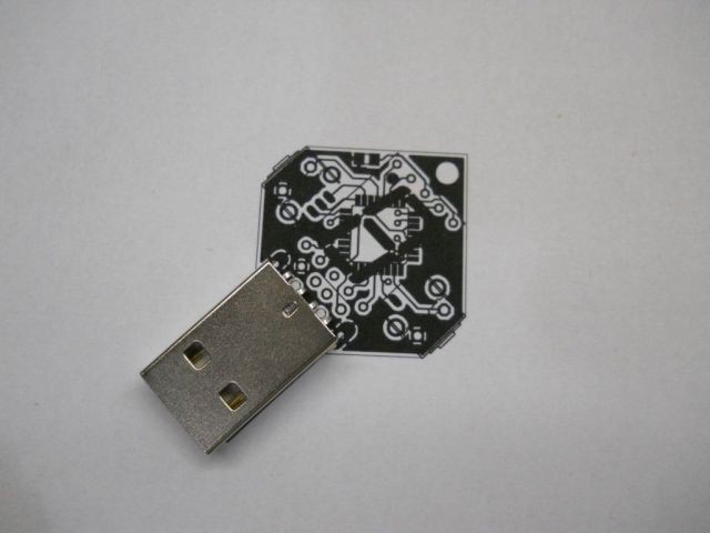
First Prototype
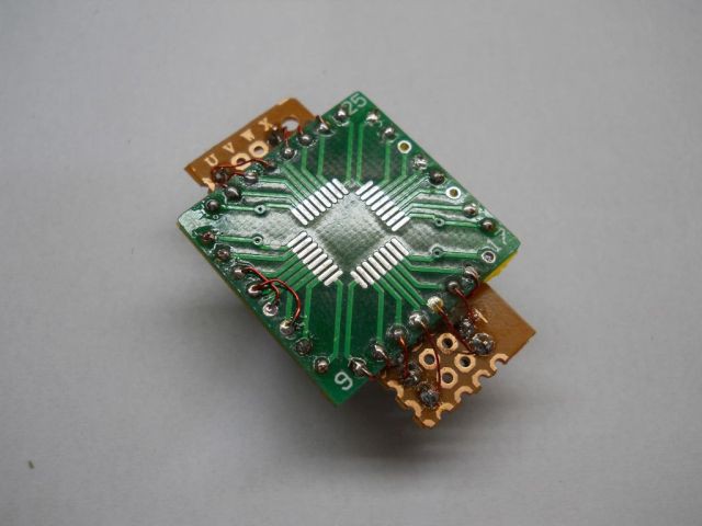
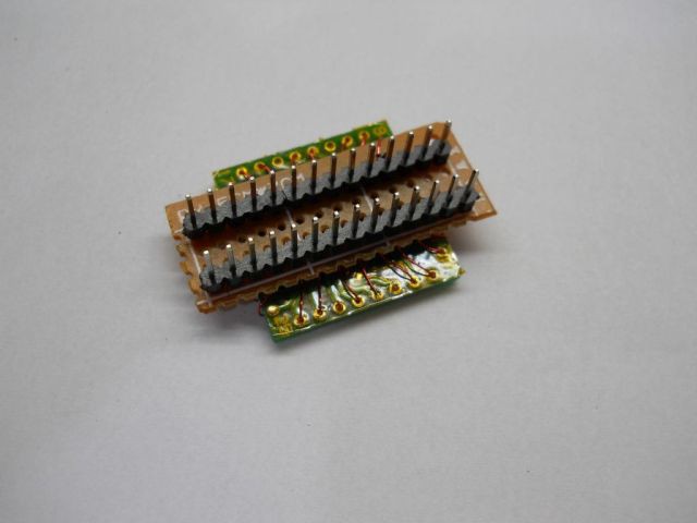
10/25/2015 at 20:33 • 3 commentsI've build a prototype for Key Pass using a piece of vero-board with a TQFP32 packaged ATMEGA8. The board has contact pins for connection with the ISP programmer.
![]()
![]()
![]()
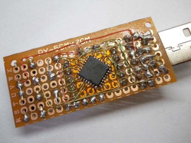
After assembling I've lost some hours trying to figure out why do the AVR refused to answer to my USBASP programmer. At some point I've started to think that the microcontrollers I've bought could be damaged. It was necessary to improvise a TQFP32 to DIP28 adapter in order to use the miniPRO programmer, pushing the chip to the board using a finger to grant contact. It was tricky but worked and gave me a clue about the problem.![]()
![]()
![]()
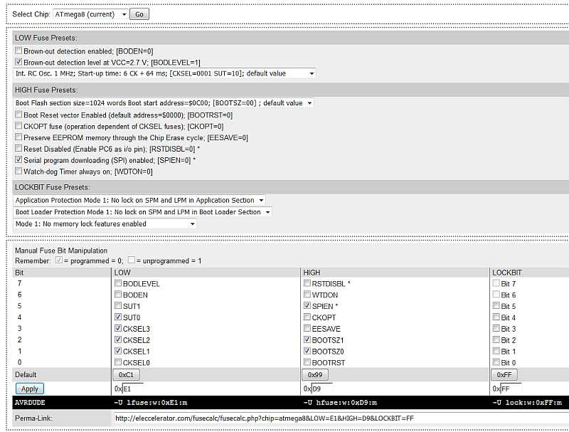
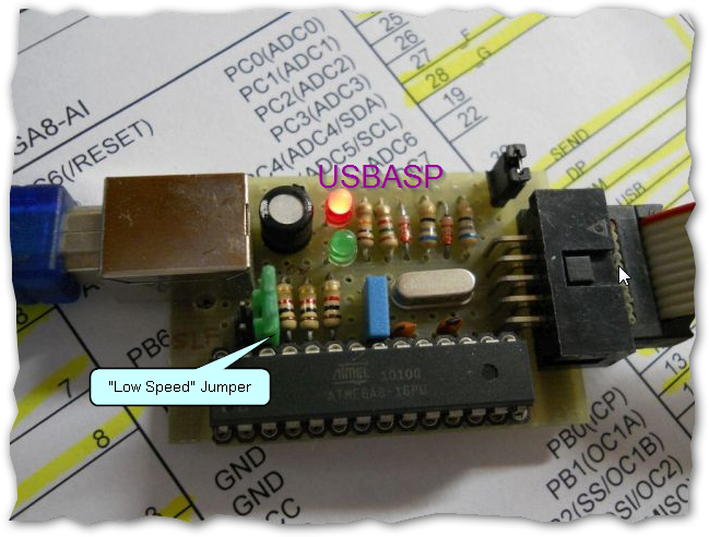
It happens that the ATMega8 I've bought have been shipped with the option for the internal 1MHZ and for the first time since I built this programmer I needed to install the jumper that configures USBASP to operate at low speed. Now the ATMEGA8 can be programmed. I am considering to use an USB bootloader .![]()
![]()
-
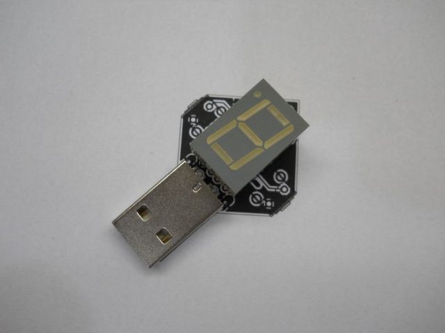
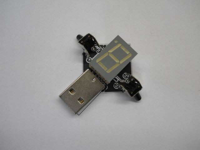
Tryout
10/25/2015 at 20:03 • 0 commentsFirst thing I've done was a try out of the components over a 1:1 image of the board. It looked well, but I'll try to find switches with smaller buttons as well as a display with less height.
![]()
![]()
![]()