 Michael O'Brien
A breif overview of why I started working on D-DAQ and what it's designed to do:
Oh, watch it on youtube with annotations turned on please. I've included CC too.
The original Doniol gauge used a 128x128 pixel, OLED displays and a MSP430 MCU. It tapped into a stock/OE Bosch MAP (manifold absolute pressure) sensor with a range of 2.5 or 3 BAR. It optionally had a daughter board for connecting a K-type thermocouple. It was simple and elegant as it fit right over an unused portion of a MK IV Jetta's instrument cluster. After researching the hardware and beginning my dive into electronics, I was able to figure out which display driver and which interface was used to interact with it. About a year ago I had the opportunity to talk to the creator and he was kind enough to answer a few questions for me even though I was in the process of starting my own project inspired by his creation.
Anyhow, onto the details about D-DAQ, you'll soon can see that for just a *simple* boost gauge and data acquisition logger, there is quite a bit of complexity here. Shush all of you who say it's undue. As a general overview to the base system design I've kept the layout simple. Feel free to start reading after the break for the nitty gritty details.
Main Pressure Sensor
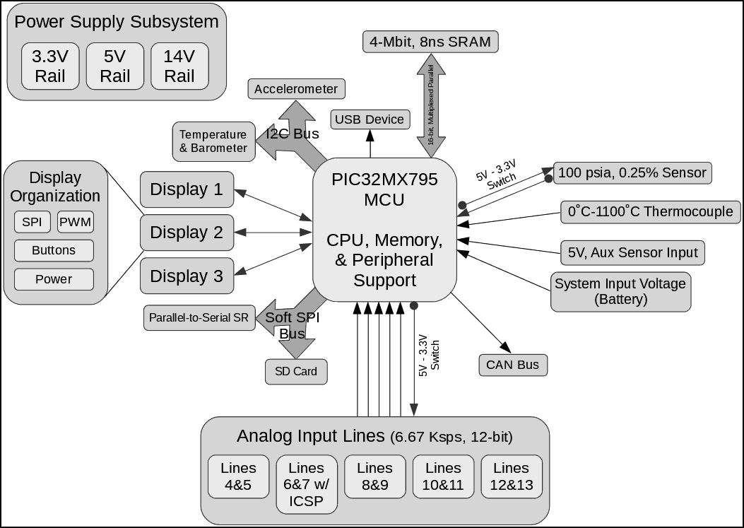
The main drawback of the original gauge was that it was closed source and hardwired to only work with two OE sensors. No code was ever released or details to help those figure out to keep it relevant. D-DAQ has an on-board 100-psi, absolute pressure sensor with 0.25% accuracy with a supply voltage range of -12V to 12V. With a dedicated I/O line for toggling a pair of solid state relays between a 3.3V supply and a 5V supply. Diesel engine require more boost pressure than gasoline engines of equivalent horsepower. Even still, there are few cars that go past 35 psi or 2.5 bar of boost. Diesel truck though, are a different story. That being said, even with the PIC32MX's 3.3V limit on the ADC, if boost pressure is below 60 psi-a, aka ~45 psi on your gauge, it is safe to use a 5V supply. This significantly increases the resolution of the sensor, which even without this trickery is capable of a resolution of 0.2 inHg. That means despite its range, it's still precise enough to measure the vacuum on gasoline engines. All ADC channels will be sampled at 60 Ksps, ~3.17 bits oversampling, to provide 12-bit ADC samples. "Huh?" You might ask. Well, I'm over sampling the oversampling to provide a better level or certainty to the output. If the ADC was capable of 12-bit samples, it would output as such. But simple nature of oversampling there will be error involved and I intend to minimize that. Anyhow, the oversampling and higher input voltage, the figure of 0.2 inHg resolution becomes 0.03 inHg.
Interface Summary
In designing D-DAQ, I want to remove so many limitations that are in current products but also give back to the TDI community something that I hope will equal the spirit of the original gauge. D-DAQ is designed around the 100-pin TQFP variant of the PIC32MX795L in order to work with an onboard SRAM buffer via a 16-bit multiplexed parallel interface, utilize 3 hardware SPI channels and 1 software SPI channel, an I2C channel, the remaining 14 ADC inputs, 2-3 Input captures, 4 PWM channels, and various control GPIOs. I won't talk much about the I2C line because it just holds an accelerometer and temperature & barometer packages. These are used for basic movement detection, ambient conditions, and cold junction compensation for the thermocouple. The single, soft-SPI interface is a dedicated one for the SD card. It doesn't need to be driven terribly fast, say 5 MHz tops I assume, but it's getting it's own line because I've read up on even name brand SD cards responding to SPI traffic even with not selected with the chip select line. Though originally planning on using a microSD card slot, I'm moving over to a full sized one instead, just in case someone becomes inventive and sticks in an Electric Imp or some sort.
Display Paradigm
The display connections are driven via the hardware SPI channels for primary communication. Though conceived with up to 3, 160x128 pixel OLED screens, evidence points to not being able to drive each SPI channel simultaneously, but instead in a round robin fashion. Due to this, the adapter boards for connecting the mini DisplayPort (mDP) cables to the display boards will have to be home to a secondary uC utilizing a SPI or Parallel bus for driving each display. If this is the case, the PWM lines from the master PIC32 will be dropped, but either way, they are there to control LED lighting for warning lights and accent LED lights on the display boards. The interface buttons have dedicated lines on the mDP cable, but are linked to a parallel-to-serial shift register connected on SPI channel 2. Due to only needing to be read out ever 5 ms at most, communication with it will hardly interfere with the display on this channel, Display 3.
Analog Sampling Backend
The heart of any gauge setup or data acquisition system is how well it can observe the parameters it needs to display. As mentioned earlier, the ADC hardware will be driven at 60 Ksps, though in order to achieve clean 12-bit outputs, the effective sample rate is ~6.67 Ksps. This is plenty fast enough to sample a crank shaft's position 10 times when spinning at 20,000 RPM. So, from diesels redlining at 5K to 6K RPM to gasoline engines spinning up to 10K RPM, there isn't a statistically relevant need to sample any faster unless you just want bragging rights. There are 14 ADC channels and 4 are taken in the base design for the pressure sensor, EGT via a k-type thermocouple, a 5V supplied auxiliary sensor i.e. an oil pressure sensor, and one to monitor the battery/alternator assuming it's the power source. The other 10 analog inputs are branched off in 5 pairs so they can nicely use micro USB, type B cables, which shield the D- and D+ lines that I'm using. These cables plug into sensor boards that are also supplied with 5V, 50 mA via the cable and the boards will contain a pair of conditioning or amplifier circuits for whatever you need. Because this is a modular setup, it's hard to know what is on the other side of the cable for the sensors. Well, taking a page from the 100-psi sensor, the power supply can be switched to a 3.3V alternate. When the boards detect this, they will divert the power to precision resistor dividers that need directly into the input lines. This voltage level will serve as an identifier so D-DAQ can know how to interpret the incoming voltage. This is a process that'll take place when the car is turned on, but can be initiated by the user through any of the displays.
Digital Inputs
There are 2, maybe 3 other inputs that need to be addressed. FYI, the third is unknown if it stays tied to the initial peripheral configuration or if it can be 'repurposed'. These are the Input capture pins. With a latency of 2 to 3 clock cycles to trigger an interrupt on a rising edge, falling edge, or a pulse, they are high performance, yet simple pins designed for reading crank position sensors, vehicle speed sensors, and even specialized sensors for some fuel injection systems. These are opposite of the analog inputs and oriented differently as well, which helps to identify their difference to the end user, while still utilizing a micro-B USB cable. They will provide live feedback to D-DAQ to synchronize data with the engine and user so differences can be more easily correlated.
SRAM, Oscillator, Misc Interfacing
To supplement functions not originally thought of, a 4-Mbit SRAM IC right next to the micro. This guy is capable of keeping up with the PIC32MX all of the way to 120 MHz if you want to "overclock" it. Now, for 3, 160x128 pixel displays at 16 bpp, I only need about 1 Mbit as a frame buffer. If you up that screen size, you might want some extra space, but you can also use it as a generic buffer for extensible communication or in case your SD card fills up while running a log. The oscillator for the micro a 20 MHz TCXO with a stability of 2 ppm. Though most timing will only be needed for 30 second logs or so, 2 ppm is precise enough for gaining or losing nearly 1 minute in a year. The USB hardware is configured as a device and will use a mini-B USB connection to differentiate itself from the general sensory inputs. Similarly, with the 795 series PIC32MX micro, there is native CAN Bus support and these pins are also accessible a mini-B USB connection, though on the other end of the board.
Interconnects & Cabling
I'm making D-DAQ extensible by nature of having the design functionally modular and using standard interconnects. Yes, this does add to the cost, but it prevents the need to find a custom part or needing to go find 3 ft of wire because of chaffed of melted through its insulation. The highest pin count, royalty free, and physically small, and inexpensive connector that I could find is the mDP connector. When utilized, 12 circuits can be taken off-board, though depending on adherence to the connectors, 14 are actually available. Because of how many inputs D-DAQ has, the end use will obviously want and need to change what information shows up on each display. Also, if something goes wrong, a visual cue needs to be present to notify the driver. Oh, and why not have it look a little cool? Either of these two lights can easily be disabled via a jumper though.
Care Taken for Use-Cases Unknown
Now, even though D-DAQ's intended purpose is to be used in a performance oriented vehicle, there isn't anything terribly specific to its function that forces you to use it for only this purpose. Even if they don't want to repurpose it, but maybe want to customize the UI, add additional features or sensor definitions, or take a peak at its inner workings. To do this I've broken out the JTAG interface. Yes, it requires an adaption PCB, but due to it's required level of know-how and capabilities, it's a cost reduction for the average use who'll never use it. Additionally, the standard ICSP pins are available. If you're keen enough to know that these programming pins are on 2 ADC lines, well, that isn't a worry. Special thanks to type-A USB cables, pins 4 and 5 are shorted together in the cable. This is taken advantage of and trips two pairs of relays to change the power line to access the MCLR pin and add a parallel resistor to the PTC resettable fuses to observe the 100 ohm max spec for the programming lines. Don't worry, when this a micro USB Type-A adapter, also known as a OTG adapter, is plugged in, the PIC32MX will detect that and switch the AN lines from analog to digital inputs. Yeah, there's extra hardware to handle all of this, but its faster and simpler than requiring the user to open up the case and change a few jumpers just to play around. Instead you just need to plug in the cable and off you go.
As alluded to earlier, the goal is to overbuild the connectivity of the device because I know I will not be able to conceive of every single way that someone will want to use it. This goes all of the way over to the power supply. It's not spec'd for just driving all of the hardware I have thought of with a little overhead in case the room is hot. It's actively cooled, but designed to sustain operation in 60˚C environments and that means I also don't expect the device to live in the engine bay ;). That all being said, every bit of information and knowledge I've acquired while designing and building D-DAQ doesn't have any significance if others cannot benefit from it. The hardware released under CERN's Open Hardware License, aka OHL, version 1.2 so those who know better than I can take the project and run with it. Sorry, but even the CC licenses' don't officially support hardware so, this is the one I prefer. Heh, there is also no reason someone cannot benefit from the mistakes I've made. Just look at my logs and start counting :p. There will also be more to come so please stay tuned.