 mr.jb
mr.jbBackground:
I wanted a charger for portable power that could be used with solar panels, TEG elements and dynamo. It was also important that the charger could take all available power. I quickly realized that LiFePO4 are the best batteries available. LiFePO4 batteries have a long shelf-life, can tolerate > 2000 charge cycles, and can accept high charge/discharge currents. They have very little internal resistance, not far from that of a super-capacitor. One of the toughest brands is the A123 Nanophosphate, with 7000 cycles at 1C before it is reduced to 80% of capacity (it can be used for spot welding or to start a car). I also wanted a wattmeter that could work down to 2.8 V (discharged LiFePO4). Long life and durability had highest priority.
Usage:
- Adjust CV (Vout) on the step-down to battery float voltage
- Adjust CC (current limit) for smaller batteries (or use 5 A to protect the charger)
- Estimate min. Vin needed for: step-down = battery float voltage (Vout) + 1 V
- Connect power source in serial or parallel to achieve sufficient Vin
- Suggested open voltage: TEG = 2xVin (MPPT)
- Suggested open voltage: solar panels = 1.25xVin (MPPT)
- Protect your TEG and solar panels with reverse blocking diodes
- When charging cells in series, use balancing circuit
Single cell LiFePO4 (8 Ah)
2x5 W solar panels (5.5 V)in parallel, or 2xTEG (12 V) in parallel
(PPXspecial edition)
CV = 3.55 V ( most of the energy is between 3–3.4
V )
CC
= 5 A (to protect circuit when charging from car battery)
Reverse
blocking diodes in cables (solar panels and TEG)
Charger design:
The heart of the charger is the step-down converter from prodctodc. I have tried at least 10 different models and what I like about this one is it does not heat up much, has a high efficiency, and can take a lot of beating. The modifications I have made to this circuit are simple; I have just inserted a reverse blocking Schottky diode and then moved the voltage sense resistor to the new +Vout. I also replaced the 470 µF Sanyo capacitors with equivalents from Rubycon. This step is not necessary; it is only done as a precaution to ensure a long life. The original Sanyo capacitor has low ESR and seems to work fine. Finally, I inserted a 0.02 Ω current sense resistor before −Vin. This resistor is used by the wattmeter. By connecting several diodes (as many as you wish) in parallel to the primary blocking diode, it is possible to charge multiple batteries at once. However, the most discharged battery should be placed after the primary diode (with CV sense). This is very useful when you leave your basecamp for a while and want to charge several cells. This is also a poor man's balancing circuit; that is, the batteries will soon have equal charge. Personally, I prefer four single cell LiFePO4 that can be combined into one 12 V battery, instead of one hard–wired 12 V battery.
Charging a battery is similar to a short-circuit, where the CC is the current limit. When the power supply is too weak, Vin will break down to approximately 1 V above Vout (battery voltage). To achieve a kind of poor man's MPPT, one should select an appropriate open voltage for the power supply (solar panel = 1.25xVin). A better solution would be MPPT (a future improvement). However, it is still possible to catch 90% of available energy from a 5.5 V panel using this simple approach.
Wattmeter design:
The heart of the wattmeter is a Attiny861 which has differential gain x1, x8, x20, x32. This means there is no need for an op-amp. Attiny861 also has four different Voltage reference sections ( 1.1V, 2.56V, Vcc (3.3V),Aref ). This gives a lot of options. I prefer to use the internal 1.1V and 2.56V Vref ( since this makes the circuit less dependent on the 3.3V supply). The 3.3V (buck-boost) voltage supply to the wattmeter is a gutted ebay voltmeter. It also has a voltage divider. The wattmeter is supplied from the battery ( Vout ). The buck-boost circuit ensure 3.3V when battery voltage varies between 1.7-25V. And finally a low power Nokia 5110 is used as display.
Less is more
I think the 0.005 and 0.02 Ω could be replaced with one 0.01-0.015 Ω resistance. This would simplify and also make the circuit more durable. The drawback is little less accuracy. I might consider to replace the buck-boost with just a 3V step-down ( not so sure yet )
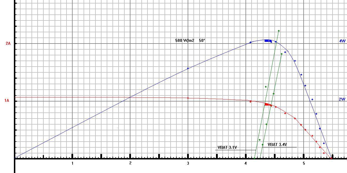
MPPT is easy on software side according to Energy Comparison of Seven MPPT Techniques for PV Systems. But a bit more difficult on hardware side, especially with a 3V control circuit. With 5.5V solar panels there is not much need for a MPPT control circuit. This chart is from an early experiment I've made with a simpler step-down ( no MPPT). The red-line ( available current ) will rise symmetrical with different light intensity. The green lines are load lines at different battery voltages ( 3.1-3.4V). The blue colored area is the power in Watt that goes in to step-down when battery voltage varies 3.1-3.4V. In this particular case 96% of available energy is received by the step-down.
Even though there is not much reason to implement MPPT ( with 5.5v panels) I still plan to try few approaches in the "future". I want a fault tolerant system ( meaning a want it to fall back to a ordinary step-down in case the control circuit fails )
1. Replace CC resistor with a digital potentiometer
2. "Wham Bam" control KEY input on step-down ( enable/disable input )
3. DAC and a oring diode to CV sense ( act like a current limit )
4. True PWM control of FET ( using the raw voltage from the Dickson doubler )
Durability, graceful degradation, and Arrhenius' Law:
The electrolytic Sanyo capacitors are probably the weakest link in the step-down, followed by the 0.005 Ω current sense resistor. Electrolytic capacitors are a necessary evil (see “eevblog: Capacitor Tutorial"). By replacing the Sanyo capacitors with Rubycon equivalents, I get half ESR and a guaranteed lifespan of 10,000 h at 110°C. For every 10 degrees of temperature drop, the life span is doubled. My primary workload is 3.55 V and 2–3A; with that load, the charger will stay below 40°C. The charger can work independently of the wattmeter. The weakest spot of the wattmeter is probably the zebra connector (i.e., display) and the 3.3 V buck–boost. Since my primary target is a single cell LiFePO4, I could connect the Attiny861 and display directly to Vout (2.8–3.55 V), in case the buck–boost fails. The reason for the buck–boost is to ensure a regulated voltage of 3.3V at any Vout.
Connectors and wires - Ohm's Law (like gravity) Is a Heartless Bitch
A big drawback when charging at low voltage is; the circuit will be very sensitive to connector and wire resistance. In fact this is the reason for the wattmeter; to detect faulty wires and connectors. I prefer XT60 on battery side,EC3 on supply side and multi strand silicone wires.
ADC reading:
ADCAccuracy Tests of the Arduino Internal ADC
Push your ATmega ADC to its limits
Software modules:
Basic Attiny programming, LCD routines , UART/Timer
Software :
The software has two modes: calibration and measure watt. The measure_watt calls an adc_read routine that reads current and voltage. Each second, 1500 ADC are read. Voltage and current are averaged in twelve measurement steps and, for each step, the wattage is calculated and the wattmeter measure increases. The display update frequency is 2 Hz. Fixed-point arithmetic with two decimals is used. Voltage and current have two ranges each. During calibration, the current and voltage are linearized to y = k*ADC + m, where the constant k is represented as k = k1/k2 (where k1 and k2 are uint32). The software UART uses a timer, which is also used to measure time
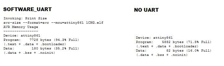
By #define SOFTWARE_UART all measurements are logged each second to PA7 9600 8n1. With this information sent to an external (connected-ish ;-) computer you can easily make charge curves and analyze your batteries over time.
The Number of The Bytes - resources used so far
Technical details :
Wattmeter :
sample rate : 250kHz
auto-range : A:[0 – 0.6, 0.6 – 6] V: [0- 10, 10 – 25]
F_CPU : 1000000 Hz
supply-current: 7.5mA
rs232 debug/charge curve : 9600 8n1
Module properties : non-isolated buck module
Input Voltage : 4-30V (limit 36V)
Output Voltage : 1.7-25V
Minimum Voltage Difference: 1V
Output Current Range : 0-5A ( peak 10A )
Output Constant Current Range: 0.3-10A
Operating temperature : -40°c to +85°c
Working frequency : 150KHz
Future improvements (add-ons) :
- Switch for display modes ( wattmeter, debug, gps, temperature)
- Measure TEG temperature ( protect the PPX from over temperature )
- MPPT ( control CC with a digital potentiometer )
- LED driver
- 5V step up USB
- GPS
Related reading :
Arduino Peak Power Tracker Solar Charger
Energy Comparison of Seven MPPT Techniques for PV Systems
Power-management functions for energy harvesting
Buck Converter Design Example Web seminar.
Choosing an RC connector, tjinguytech
SM74611 Smart Bypass DiodeHistory :
Chargers and batteries I have tried before I decided to make the 1Charger....
NiMh
Maha MH-C401FS NiMh,Imedion AA 2400mAh, Guide 10 Plus Recharger
Li-ion
Adafruit, solar Lithium Polymer battery charger, LiPo Rider Pro,
ML-102 V6.0 USB Charger For 18650 / 26650 battery, TP4056,
LiFePO4
Sherpa 50 LiFePO4 12V ( with MPPT ), Xtar MP2,