 Quinn
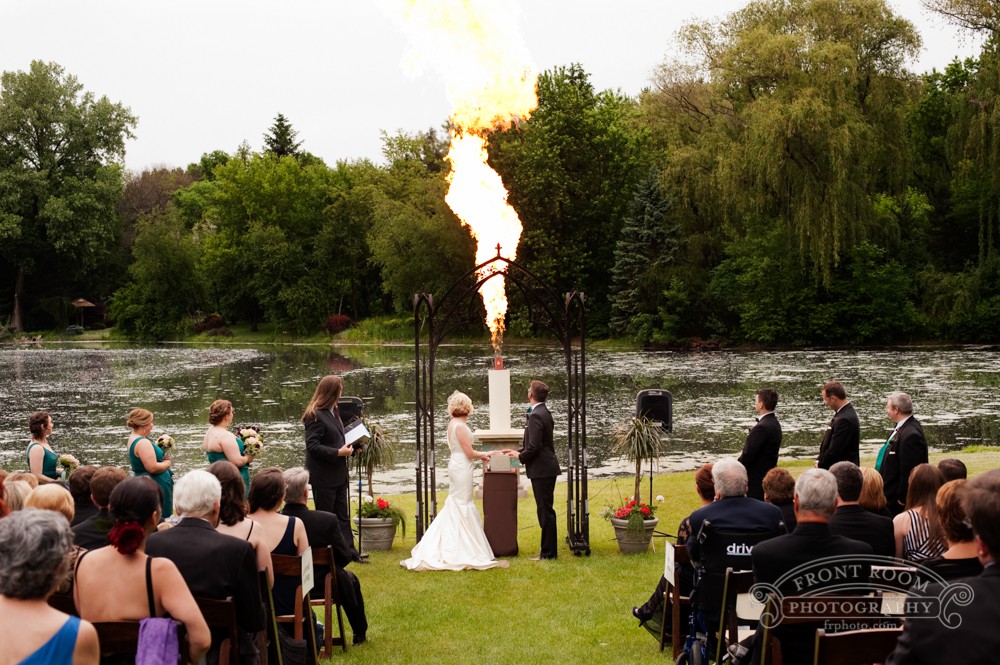
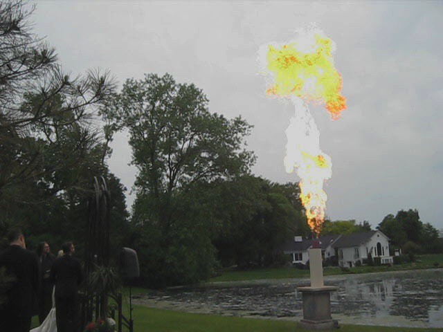
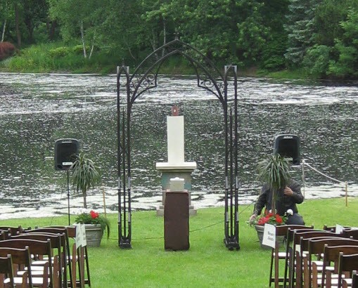
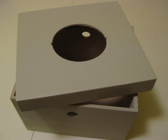
QuinnA "Unity Candle" is sometimes used in a wedding to symbolize the two people coming together. Each participant uses a small lit candle, and together, they light a larger Unity Candle. Continuing this symbolism, but representing the background of this particular couple, they sought a much larger flame. A control box is located in the ceremony space to allow the couple to light the candle. It has a large firing button on the top, and key switches on the sides. They each have their own key to symbolize their joint efforts coming together. Once armed with the key, the large button becomes active to fire the candle. When fired, a 30 foot high fireball comes out of the candle itself.
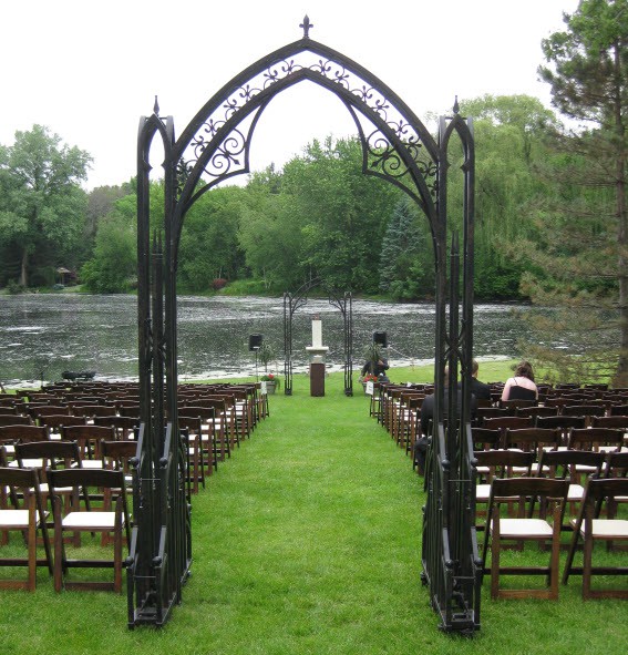
Front Room Photography took this fantastic photo during the ceremony:
How the ceremony came together: (this is not the THP entry video, see link on left for that)
If you have any questions or comments, please use the comment box below.
Project log index:
More details
How it all worked out
Installation and setup of the system on site
Wiring the system on site and being a connected device
Construction of the firing button and keyswitches
Discussion about electrical robustness in this system
Rain shield for the hot surface ignitors
Estimating the heat output and costs of operation
Additional testing of various sequence parameters
Building the decorative shell
Code running on the Arduino Micro
Added circuitry, schematics and design notes
Modifications to the controller
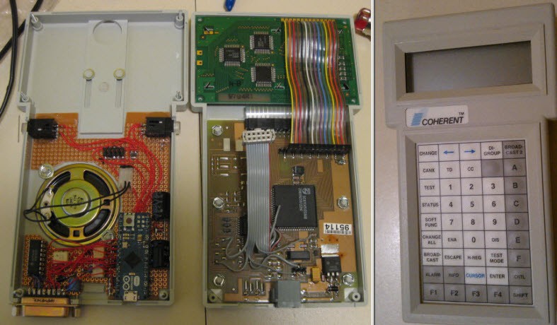
Reverse engineering the existing hand controller
Notes on getting the parts
Initial manual testing of the propane poofer
Mounting the ignitors
Building the relay board to drive the poofer
Assembling the propane poofer
Initial discussion of safety design
Researching details of a propane poofer and possible improvements
Researching methods of making a fireball
Disclaimer: This project should only be attempted by those who fully understand it and have appropriate training. This project information is not appropriate training which must be sought out elsewhere. Anyone attempting must comply with their local ordinances and codes.
THE PROJECT DOCUMENTATION AND MATERIALS ARE PROVIDED "AS IS", WITHOUT WARRANTY OF ANY KIND, EXPRESS OR IMPLIED. IN NO EVENT SHALL THE AUTHORS OR COPYRIGHT HOLDERS BE LIABLE FOR ANY CLAIM, DAMAGES OR OTHER LIABILITY FROM THE USE OF THIS CONTENT OR OTHERWISE.


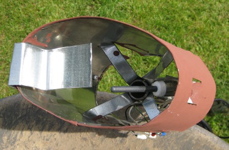
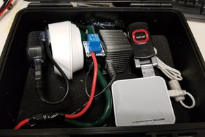
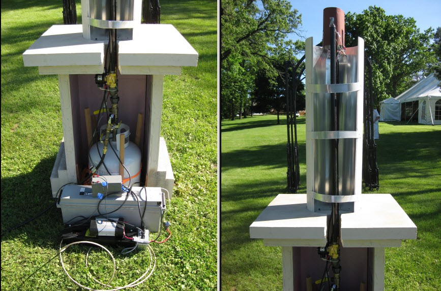 Behind the shell was a large industrial deep cycle battery(grey). This powered an AC inverter(black and grey, up front of the large battery) to power the hot surface igniters. I didn't measure the HSI's, and they didn't come with a datasheet, but both were powered fine with a 400w inverter without causing an overcurrent on it.
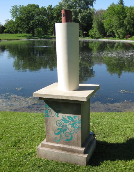

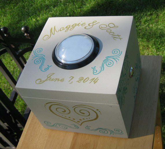
 The box was placed on top of a tall table(a plant stand I believe) in the ceremony space. This picture was from the rehearsal. For the actual ceremony, the table was covered in a table cloth matching the wedding colors, and the wire was buried. The table was also attached to a pair of stakes to make it level.
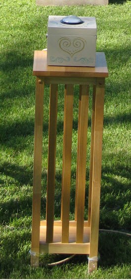


 mark.reeves.78
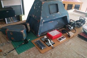
 Andrew Bills
 Steve Hernandez
Are you just advertising?