 Quinn
QuinnSeveral pictures of the nearly finished plumbing. The first is of the accumulator tank end:
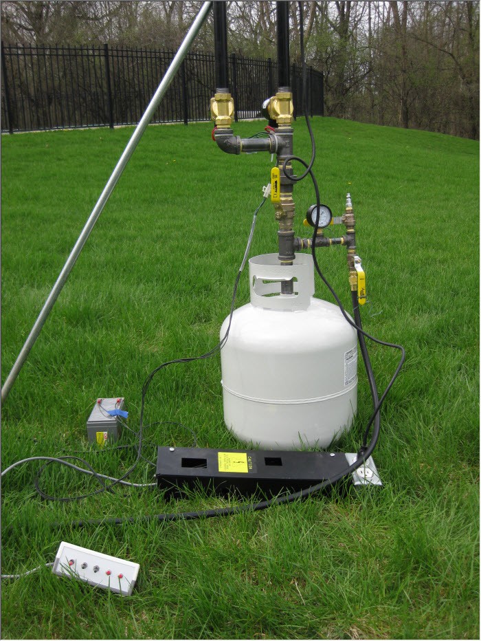
The accumulator tank is at the bottom. I sourced a new, purged and never used LP tank from the hardware store to remove worries of residual propane when removing the fitting. The normal fitting must be removed because we require vastly more flow from this tank than it can provide. Though it is a standard 3/4" NPT threaded fitting into the tank, it is glued in. In the end, I constructed a version of a "propane tank valve wrench" out of a 6" segment of 3" black pipe. I crudely cut out notches on both ends with an angle grinder. Had I realized that this type of wrench is easily available online, I might have purchased one instead of constructing. I used a truck tie down strap to strap the tank to a long large board, and a segment of pipe to turn the valve. I used a heat gun on the tank near the valve(not on the valve; metal expands when it gets hot), and with probably 200 foot pounds of force it turned.
Above the tank is a collection of fittings, nipples, T's, etc to make all the connections. The main flow path is linear with no bends to facilitate maximum flow, and is all done with 3/4" black iron pipe. Black iron is required for gas use, and is rated for LP. All connections are threaded, and sealed with yellow teflon tape as required for gas use.
A 3/4" ball valve is included above the tank and functions as the manual shut off valve. With this closed, gas cannot be vented, no matter the state of the solenoid valves. A ball valve is used for maximum flow, and quick shutoff. Above this, is another T, and the two solenoid valves(brass) which lead to the barrels. The solenoid valves must be rated to support LP gas as it is semi corrosive to seals. These have Viton seals. The barrels are about 4ft long so that all added together the exit aperture is just above most people's head height.
Split off the main pipe from the tank, is an area using 1/4" pipe. 1/4" can be difficult to get, so check your suppliers before assuming you can get it locally. Attached on this branch is a gauge to show what pressure is present in the tank. I used a 200psi gauge per recommendation that it should be double any working pressure. I designed to work up to 100psi, though I don't think it will ever be used that high. I probably should have gone with a 100psi gauge for better scale granularity.
Past this are two fittings with ball valves isolating them. One goes to a 3/8" flare fitting for the LP hose, and the other to a standard tool air supply fitting. The flare fitting is for the input. The air supply fitting is for pressure and leak testing, as well as to purge the tank.
All ball valves are oriented so that when closed, they are less likely to be bumped into an open position.
The angled silver colored pipe is a stake, which is being used as a precaution so that the system won't tip given the uneven grass.
I'll cover the electrical elements separately.
The second picture is of the source tank end:
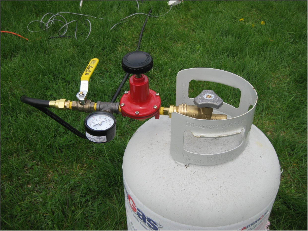
This is a standard, full LP tank. Connected to it is a full bore POL fitting. The large hand screw type fitting used on a grill has limited flow, and we require about 10 times that. a POL fitting screws into the inside threads with a reverse threaded nut.(counter clockwise to tighten)
The POL fitting is connected to a high pressure regulator. This is a harder part to source as most regulators have several up to maybe 20psi. In this application, I needed to support higher than this. I chose a 100psi model, though a 60psi probably would have been sufficient. Again, this regulator must be rated for LP gas.
Past this is a gauge to show the regulated pressure. And past this is a ball valve, and another 3/8" flare fitting for the LP gas hose. The hose must be LP rated.
When all connections were made, I used an air compressor to pressurize the system at 100psi, and gas leak detect fluid to check for leaks. This is the first time I've done this many threaded connections, as well as the first time I've done gas, so I will take it as a relatively good job that out of 28 connections, only 2 leaked. I removed, cleaned off, and re-taped and fitted them, and resulted in no leaks. I've always heard the idea of using soapy water in a spray bottle, but I have to say this lead detection fluid is way better. It really stays on the joints for an extended time, and makes easy to see bubbles.
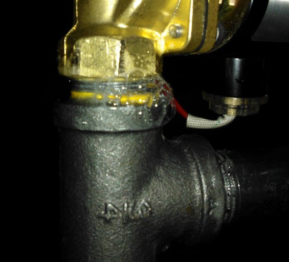
It cleans up easy by just wiping with a paper towel.
With leaks gone, I left it pressurized for several hours, with no change to the gauge reading.
Note that I could not test the connections between the POL fitting and the first valve after the regulator. The regulator does not hold pressure backwards. For those, I tested the connections using the LP tank later.
Discussions
Become a Hackaday.io Member
Create an account to leave a comment. Already have an account? Log In.