 AVR
AVRSunLeaf
An Open Source Sensing Module
Abstract
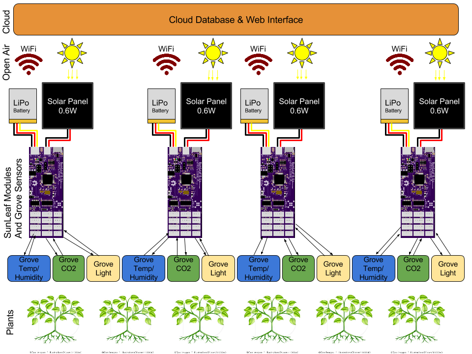
The SunLeaf is a wireless sensor module for remote sensing applications. The module is solar/battery powered, low power, connected via WiFi, low cost, and highly scalable. SunLeaf interfaces with several variety sensors, samples, and transmits the data to the cloud. Data is viewed through a web interface. The SunLeaf module intends to be a solution for many remote wireless sensing applications, such as plant health, agriculture, monitoring pollution, and monitoring climate.
Overview
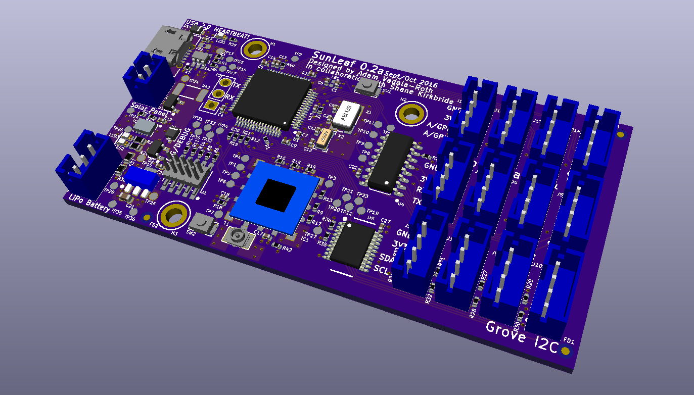
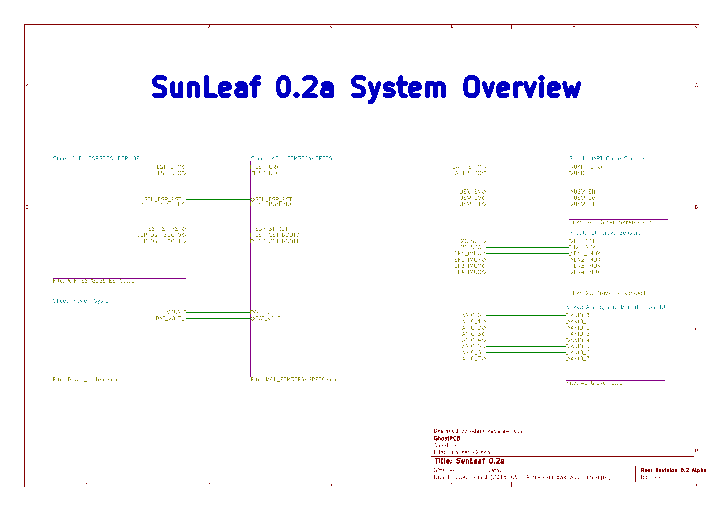
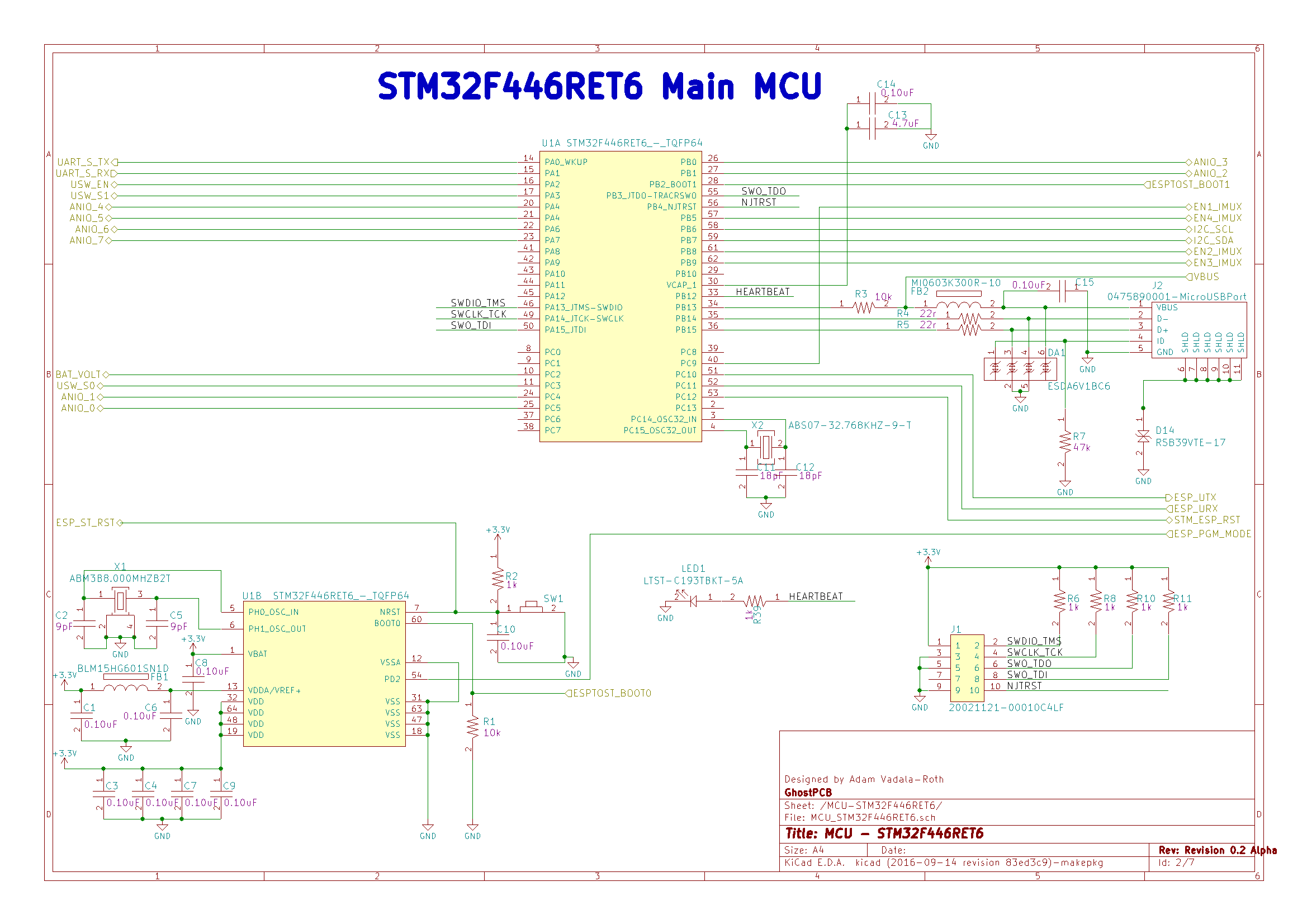
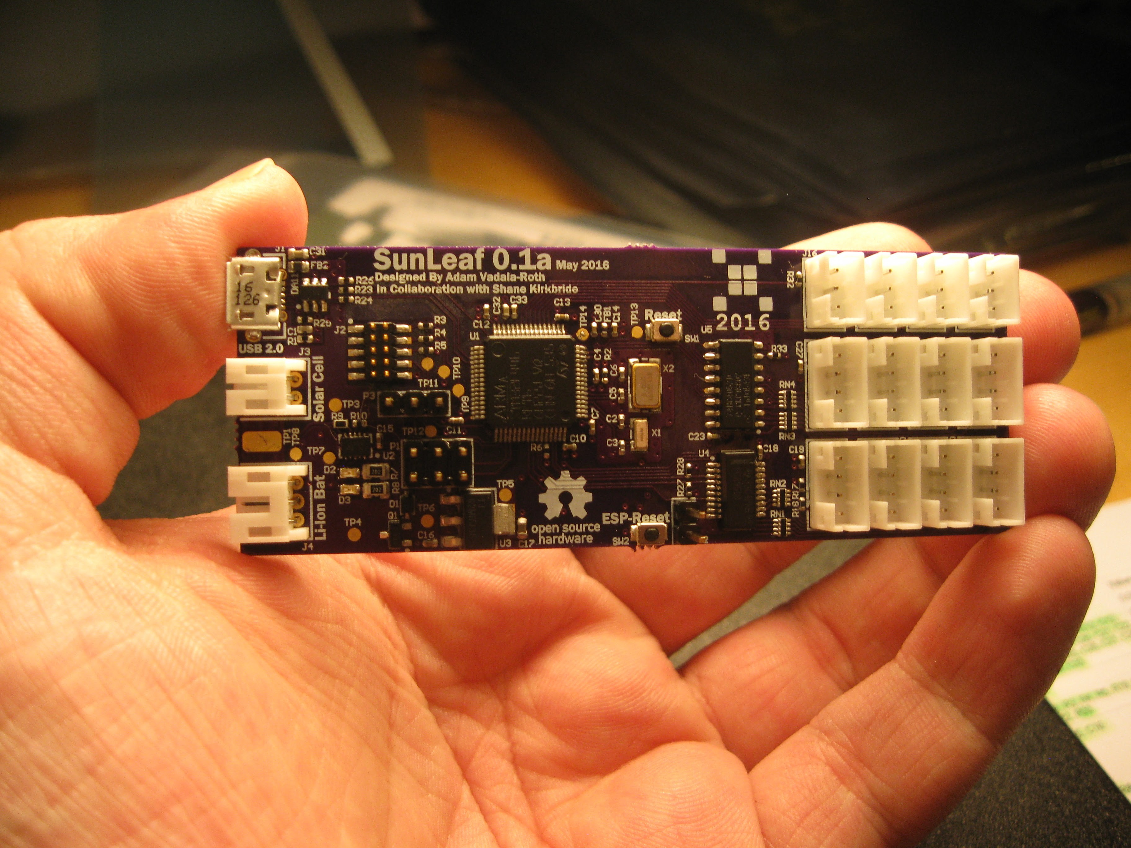
SunLeaf is a wireless sensor module for remote sensing applications. The module is a simple low power device that interfaces with sensors and transmits that data to the cloud. The SunLeaf hardware makes up a rather complex printed circuit board. The brains of the device are an ARM Cortex M4 microcontroller and an ESP8266 module. The ARM interfaces with the sensors, and is the general brains of the device, the ESP8266 acts as a dedicated WiFi modem and interface to the web. SunLeaf will be able to perform firmware updates over the air. Sensors connect to the module via SeeedStudio Grove sensor connectors, SunLeaf accepts up to four UART, I2C, and analog/GPIO variety sensors. Module power is supplied by an onboard lithium ion battery, of which is charged by an onboard charge controller via solar panel or USB. Configuring the module for a given sensing application is performed by connecting with a PC either over USB or WiFi. The data logged from the sensors attached to a SunLeaf module is logged into https://thingspeak.com/ channel.
Inspiration, and Why
SunLeaf has roots dating back to HydroPWNics in spring 2015. Originally SunLeaf was going to be a redesign of the sensor modules and module hub as a standalone board. A module for interfacing with both digital sensors and analog sensors transmitting it over WiFi. Just being able to interface sensors and transmit data wirelessly wasn't enough, so the ability to run off a solar charged battery was added as a core feature. Solar power is an important feature because the module will be self sustaining also it makes the project innovative being one of the first solar powered sensor modules of this kind. All those features packed together made the module capable of much more than monitoring plant health and the environment. In short SunLeaf is a solar/battery powered pic power wireless sensing module for all wireless sensing applications.
Applications
Hydroponics:
SunLeaf has its roots in hydroponics, given that it is an evolution of the original hydroPWNics project’s electronics. In the application of hydroponics SunLeaf would be employed for monitoring the environment of the plant grow room. Multiple SunLeaf modules would be deployed along with a multitude of SeeedStudio Grove temperature and humidity modules. Additionally a single SunLeaf with equipped with Atlas Scientific (https://www.atlas-scientific.com/ ) pH, dissolved oxygen, electrical conductivity, temperature, and ORP sesnsors, these sensors will allow precise monitoring of water quality and with software monitoring of the nutrient content of the water. The same SunLeaf in charge of water quality monitoring would also be setup with additional hardware for controlling pH and delivering nutrients to the water supply. All SunLeaf units in the grow room should be able to run off excess light from the grow light units.
Water Quality Monitoring:
As mentioned in the hydroponics application SunLeaf also has use in water quality monitoring and management. The application is not limited to hydroponic water monitoring. Another application is pool water quality monitoring, make sure there isn’t too much or too little chlorine in the pool. A SunLeaf would be setup in a waterproof enclosure with the right probes with the solar panel on top, it would just float in the pool and run of the sun. In some parts of the country some folks do have access to water utilities provided by their town, in this case they have a water well that...
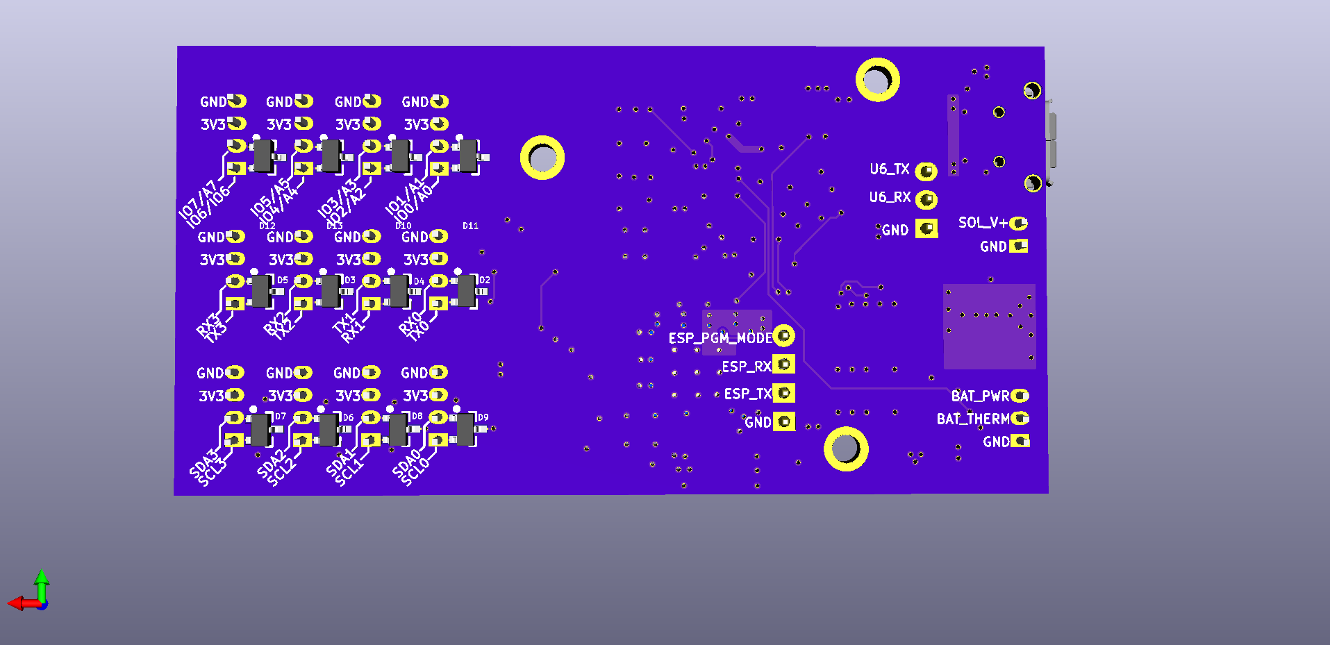
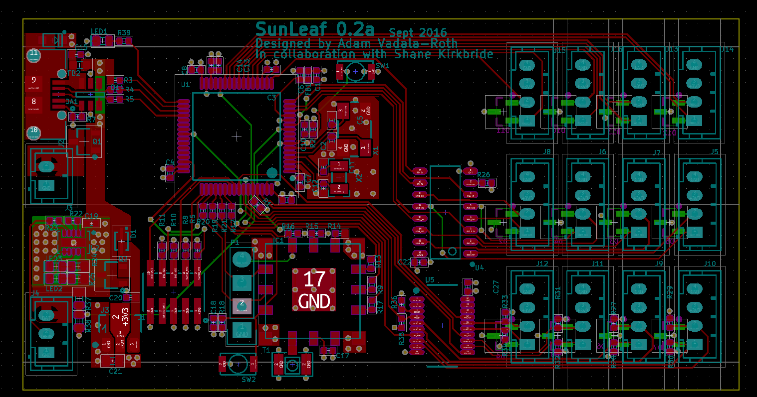
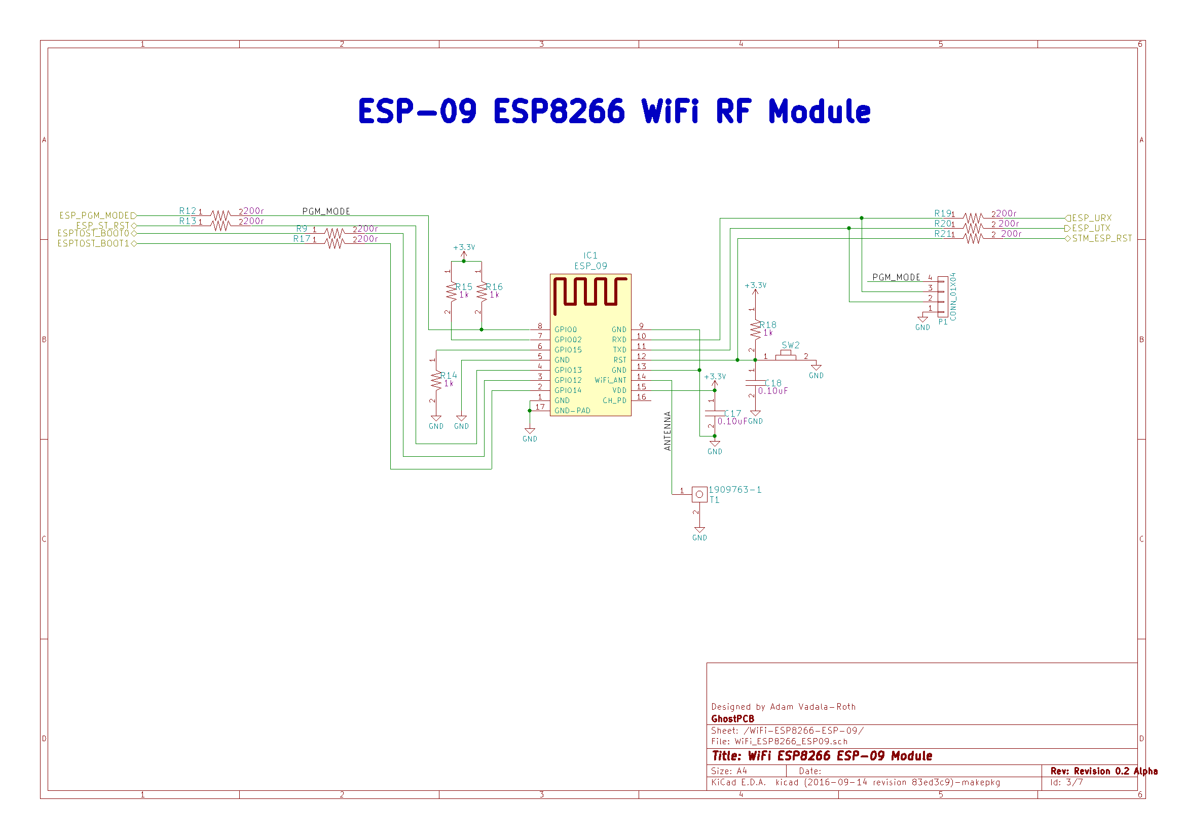
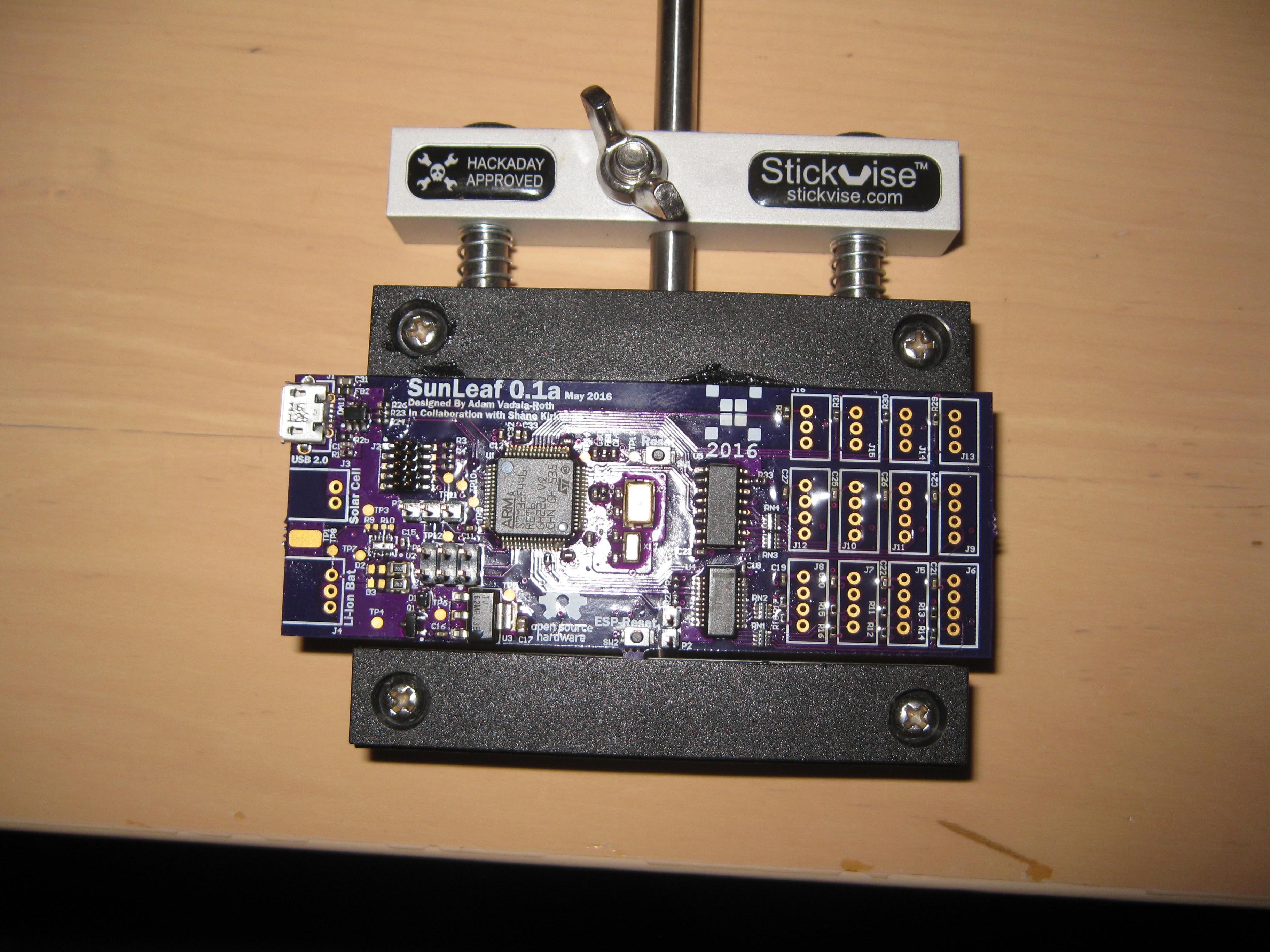
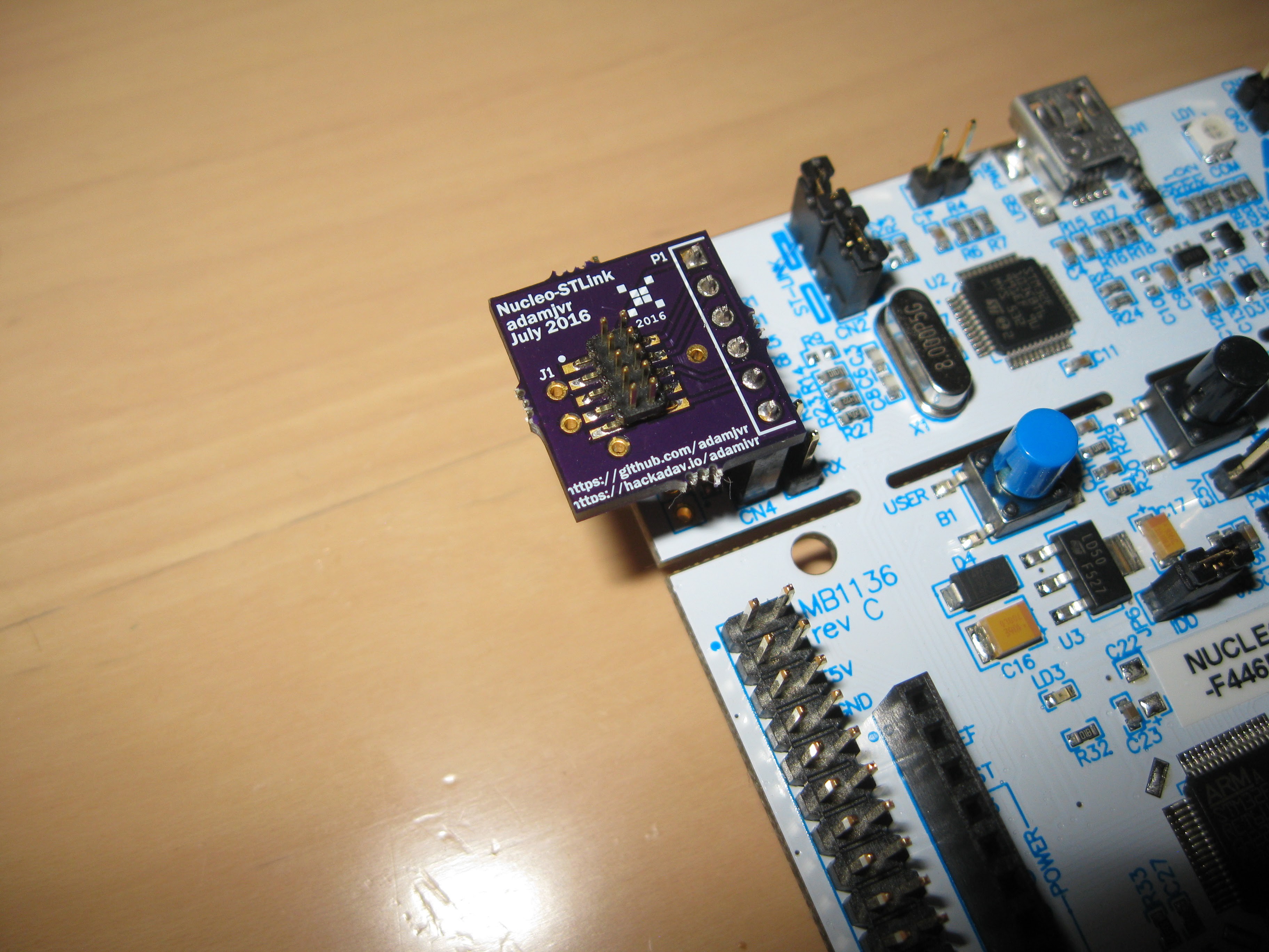
Read more »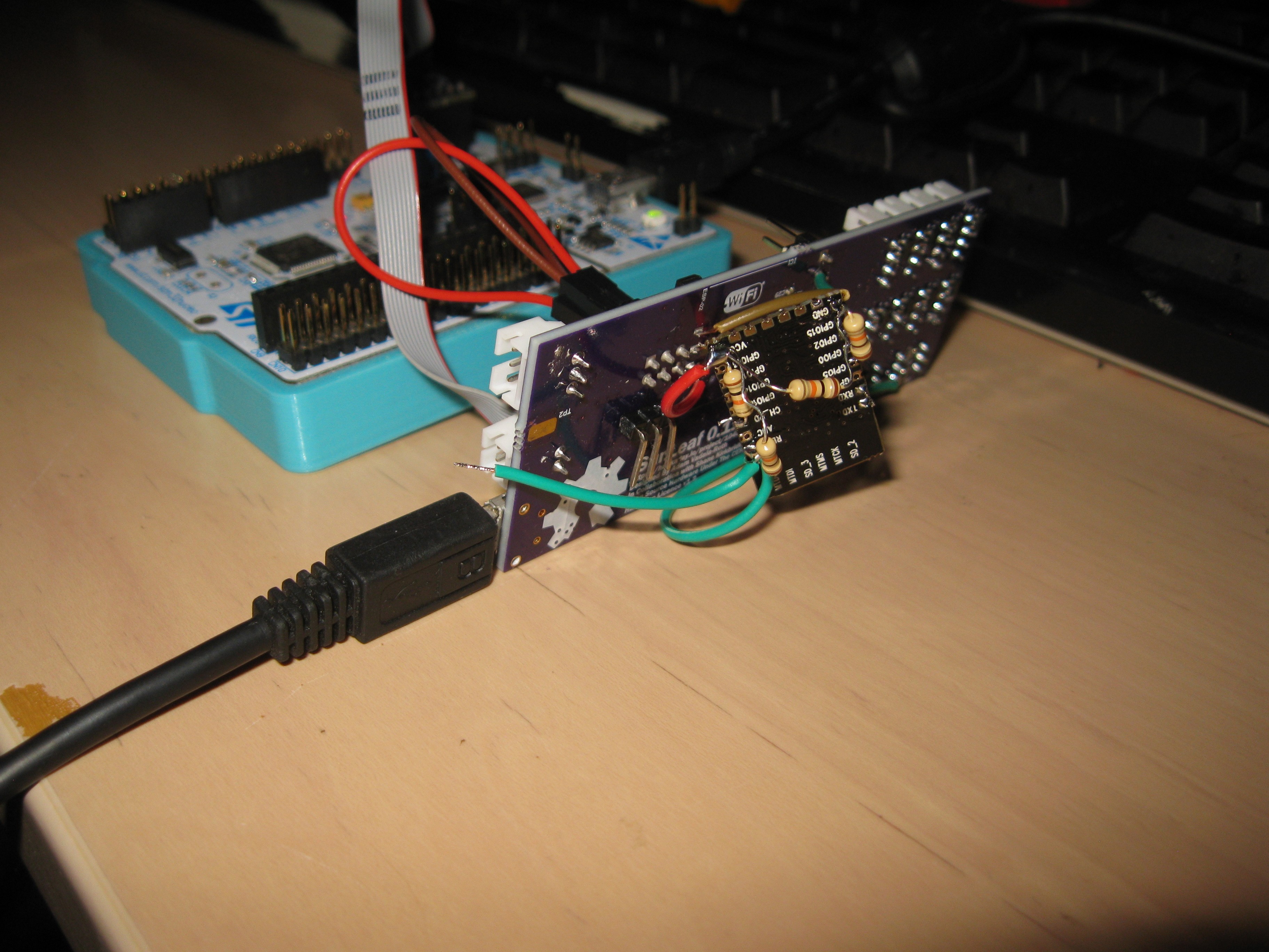 Not my proudest moment or cleanest assembly/build but the damn thing works! And it even works well off battery power (battery not pictured). What is next is to create a version of the PCB that works flawlessly. I have already teased and shared the nearly solidified SunLeaf V2 design a few times arleady. The reason why it has yet to be fabricated is because the WiFi module needs to be tested separately. On the open web there are not many people using the ESP-09 module, I am using it since its very barebones and allows for a smaller PCB layout allowing my to mount it top side on the rev2. So in order to confirm this module before running another 4 layer PCB through the fab process, I made a small two layer PCB that will allow me to test the ESP-09 module and our software for the ESP8266.
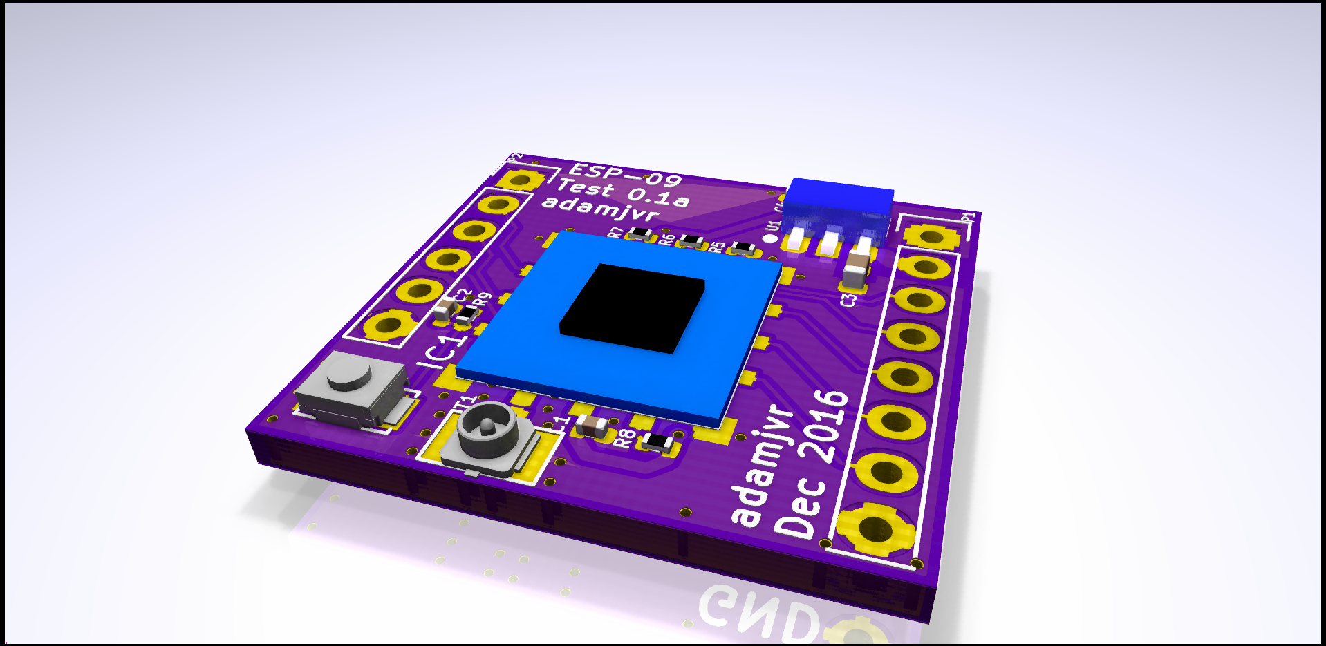


 pastcompute
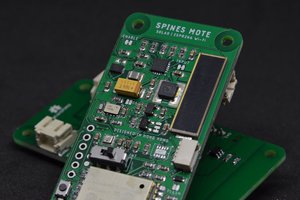
 Joshua Young
 Dorijan
Nice