 infinityis
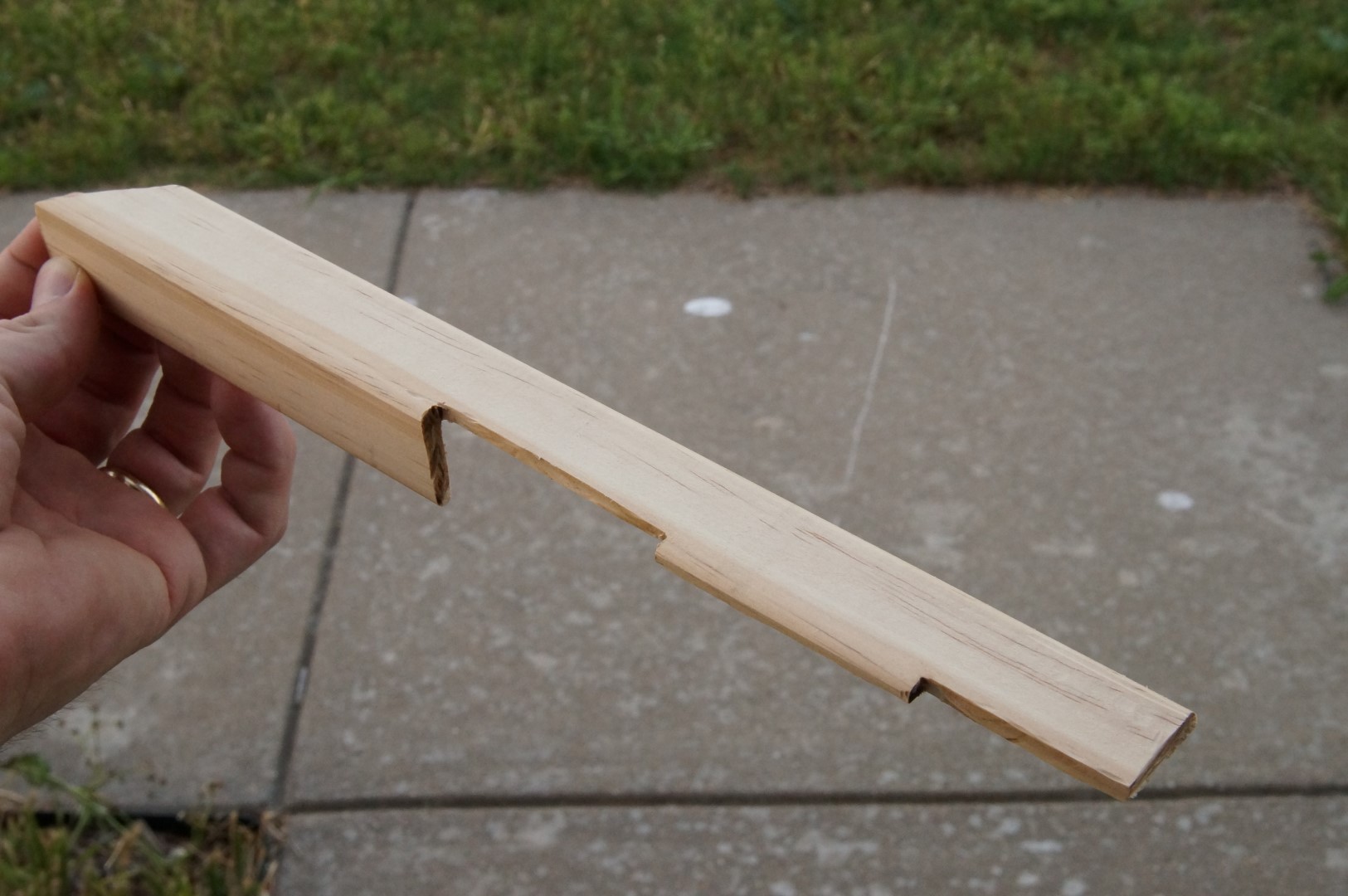
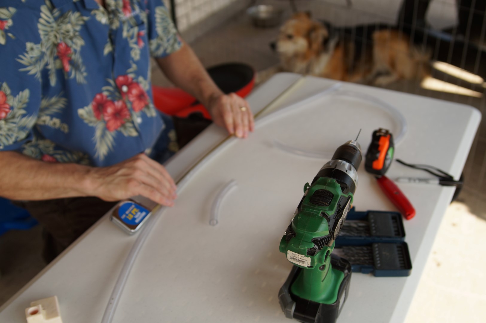
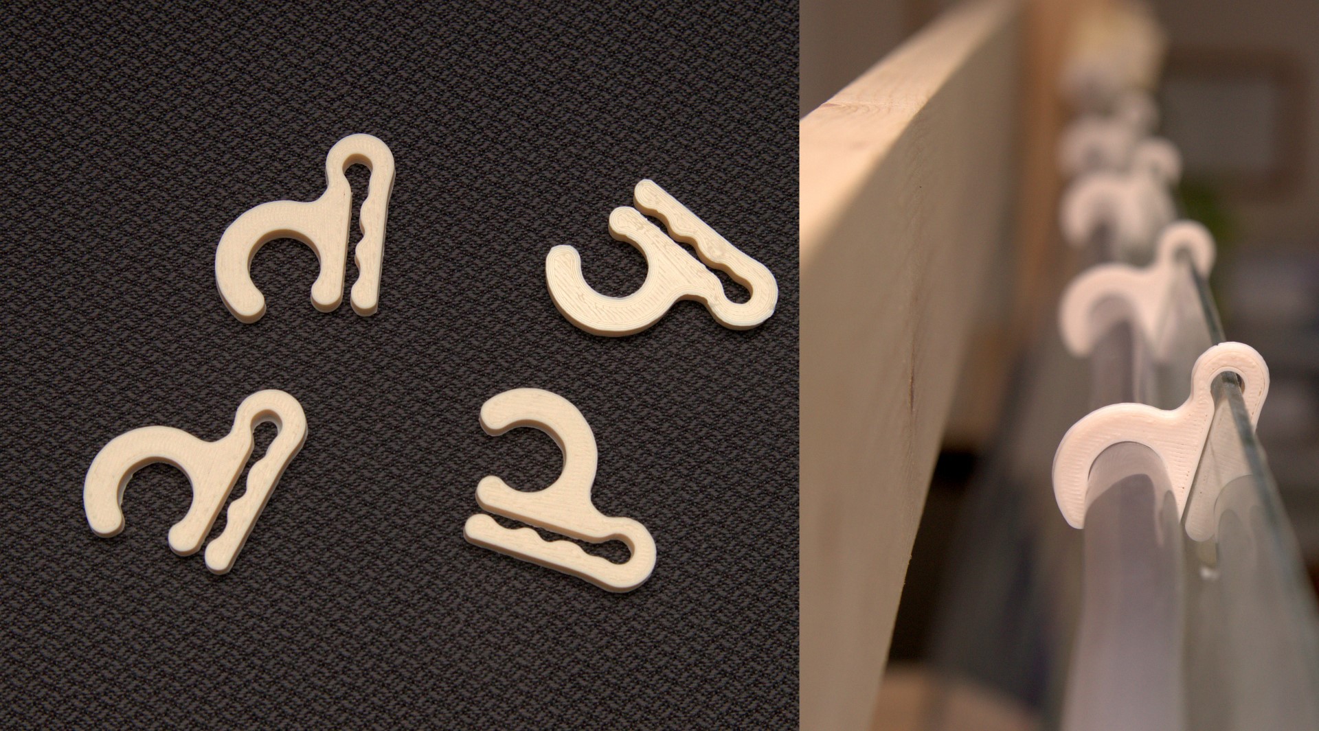
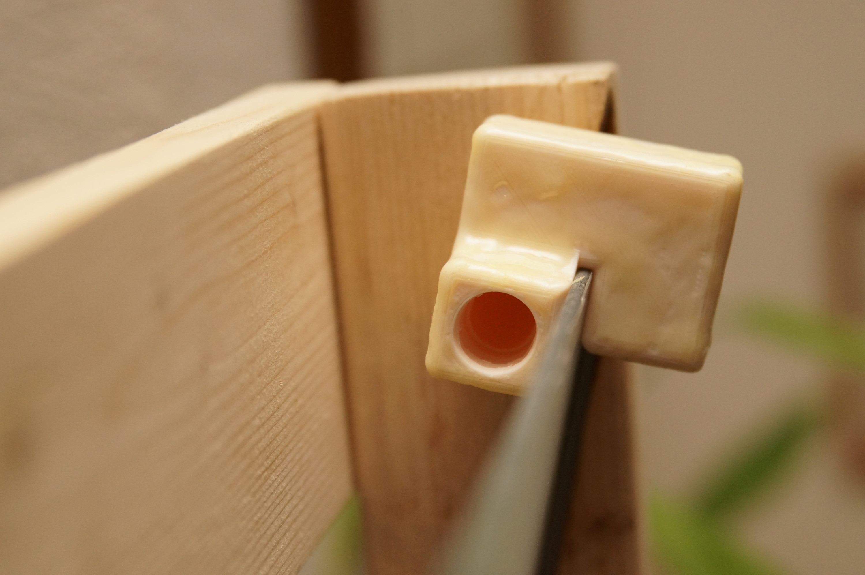
The Waterfall Wall with LED Illumination encompasses many different domains including electronics, woodworking, programming, plumbing/water management, and 3D modeling/printing. Consequently, it is challenging to capture the comprehensive capabilities and characteristics in a consolidated design document. In recognition of the emphasis Hackaday places on the connected nature of devices, my primary focus will be on the electronics and programming portions of the effort with the hydro-mechanical aspects playing a supporting role.
Videos
System Design Document
Below is the design document showing how user input data moves from a convenient control interface toward changing the state of LEDs and controlling water pumps. It is a perilous journey, taking two hops over the air and ultimately dealing with high voltage (for the AC-powered pumps) and high current (for the LEDs). The "connected device" requirement is met through multiple wired, wireless, and software data transformations (e.g.: User interface -> Python data handling -> Telnet -> 802.11 -> Ethernet -> Python data handling -> SPI -> 2.4GHz wireless of some kind -> SPI -> MSP430 data handling -> WS2812B protocol via SPI)
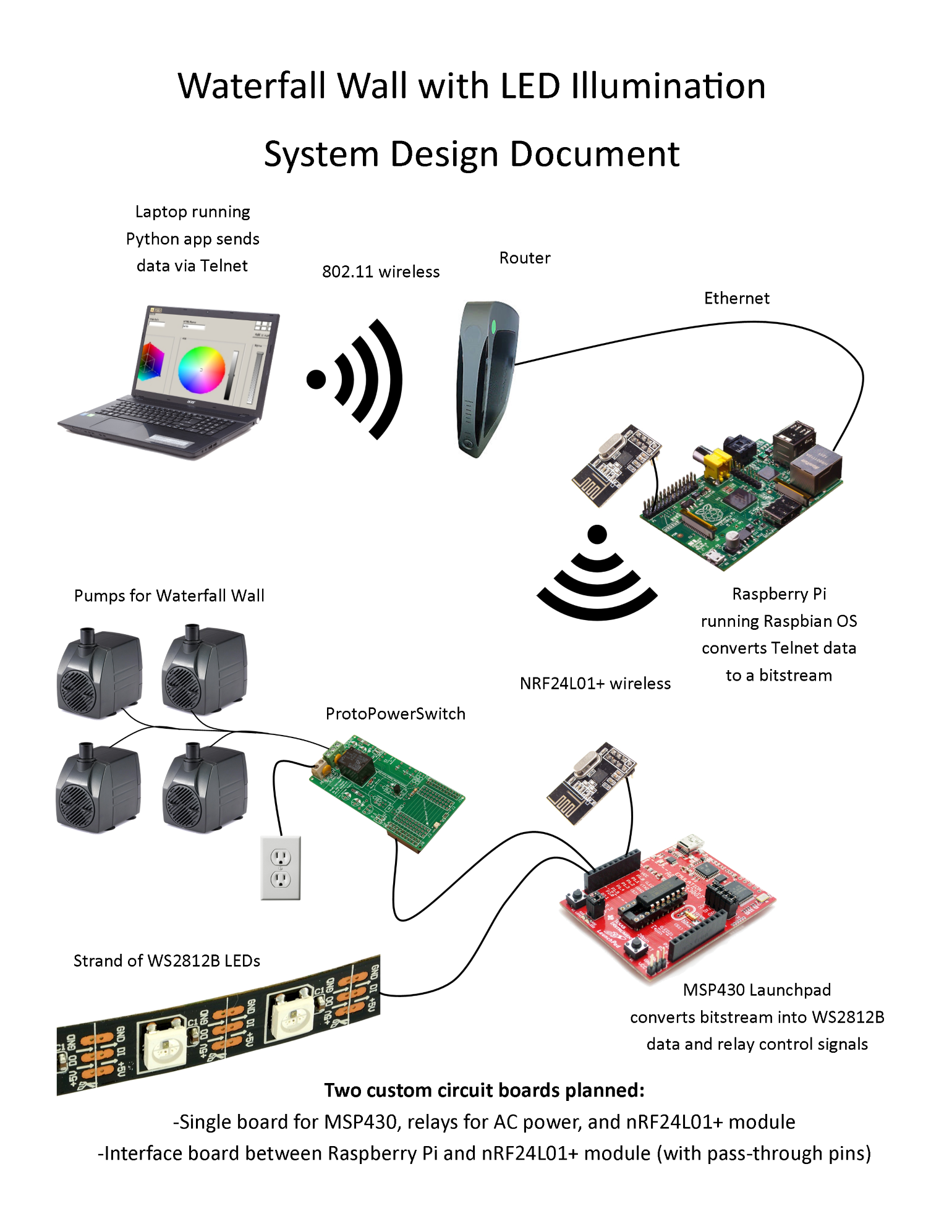
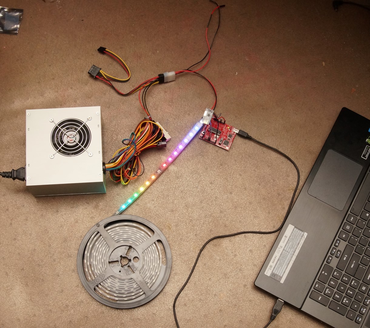
At the moment, the system is very much in a prototype configuration: there are jumper wires going to each nRF24L01+ wireless board, the MSP430 Launchpad is only intended for microcontroller prototyping & development, and the ProtoPowerSwitch board is intended for prototyping and development of circuits interacting with AC mains voltages.
As of 11 August 2014, the main design path has been verified operational; that is, I can use a Python color picker app on my laptop to control the LEDs by sending data along the path shown in the system design document.
The next step will be to design and build circuit boards to get all the capabilities into a much smaller and more product-like package. After the boards are designed and sent out for fabrication, I will have a good opportunity to modify the software codebase (on the laptop, on the Raspberry Pi, and on the MSP430) to improve the capabilities of the final system and make the code more clear/documented/useful to other open source hackers.
Open-source licenses and permissions
This project would not be possible without the support and examples provided by many, many open source contributors:
LED controlling software for MSP430 was derived from GitHub user RoXXoR with no license specified; GitHub T&C includes rights to view and fork.
The color picker Python app is derived from the wyPython cubecolourdialog created by Andrea Gavana, licensed under the wxPython/wxWidgets/wxWindows license
The MSP430 wireless code is derived from nRF24L01+ Library for MSP430 provided by GitHub user spirilis under ISC License
Python is licensed under the Python License
Raspbian is licensed under the GPL.
Quick2Wire for the Raspberry Pi is dual licensed under the MIT License and LGPL.
nRF24L01p.py is from GitHub user klalle with no license specified; GitHub T&C includes rights to view and fork.
miniboa-py3 (Python 3.0 Telnet server) licensed under Apache License, Version 2.0 (note, I had the same issue/fix found here), Server codebased derived from the included miniboa chat room example.
And this link (previously featured on Hackaday) was very helpful as well


 Darian Johnson
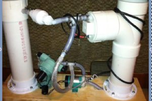
 Scott
Scott
 ProgressTH
 Evan Salazar
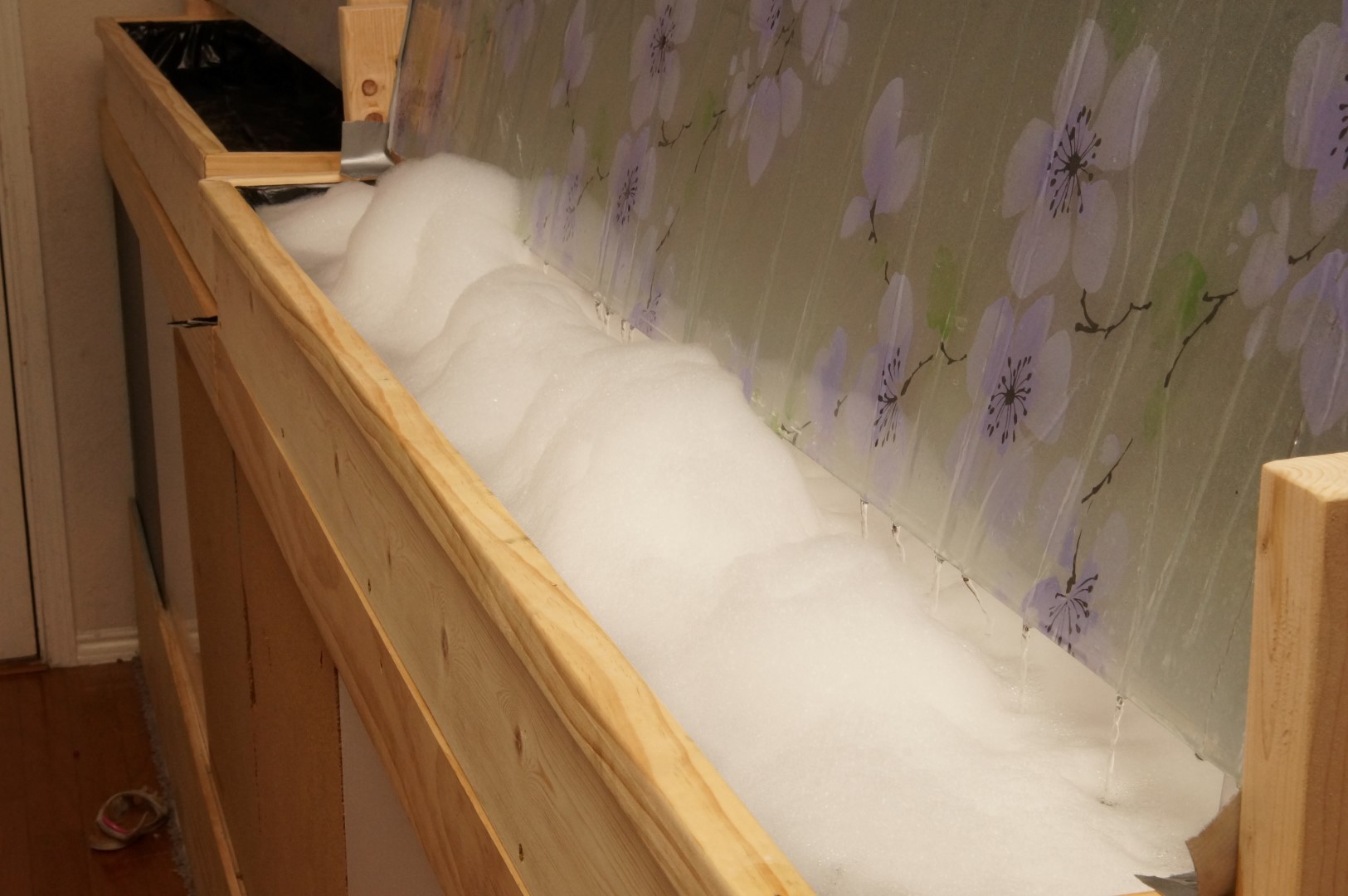
I LOL'd about the laundry detergent. Reminds me of a prankster who dumped a bunch of soap in a fountain one day at the University I attended. Turned out like a foam party at Ibiza!