 GearheadRed
-
1Step 1
Bike Module
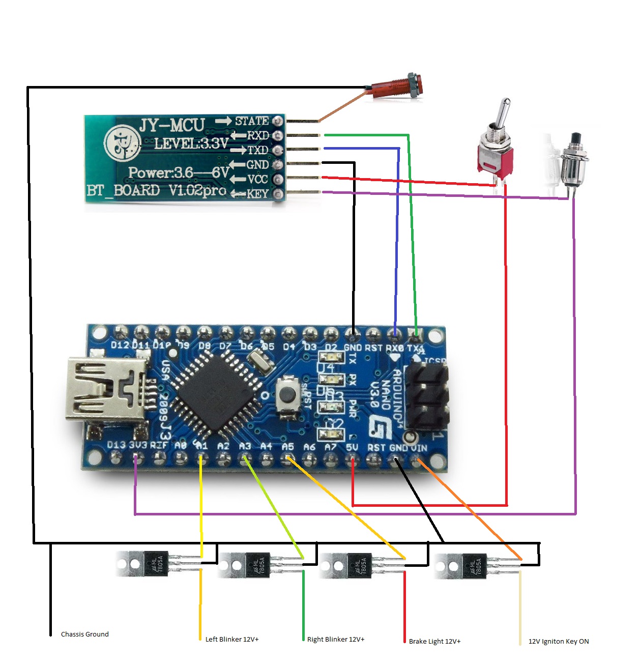
Wire up the bike side module. I made up a really straight forward picture for this:
![]()
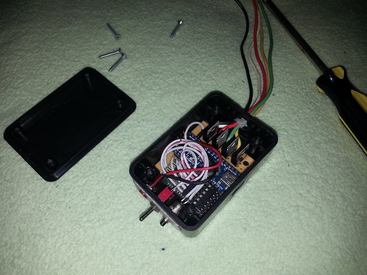
You can solder everything down to one of the mini perf boards to hold everything solid and mount it into the project enclosure like I did, or design your own assembly method and enclosure. I was lazy and skipped designing a printable case or custom etched primary board for this part as design was not as large of a concern with it being mounted within a motorcycle chassis.
[NOTE IMPORTANT: mount this module away from heat sources like exhaust or oil reservoirs on motorcycle chassis unless you enjoy melted stuff and fires.]
Program the Arduino with the BikeModule.ino sketch from github.
No changes to the sketch should be necessary provided you followed the wiring diagram above, but feel free to modify the wiring and sketch as you see fit for your particular design/needs.
![]()
Operation:
The mini switch turns off the Bluetooth module, which allows for the USB reprogramming of the Arduino. Turn on the mini switch and the indicator light will start blinking. This is the bluetooth module attempting to pair with a jacket module.
If the module has already been paired the light will blink until a connection is established with the jacket module, and then the indicator will remain steady on.
If the module has paired and you would like to release the pairing to pair with a different jacket module, press the SPST Momentary Switch to release the pairing.
It is suggested to only have one jacket module turned on and within range of a bike module at a time during pairing operations.
-
2Step 2
Jacket Module
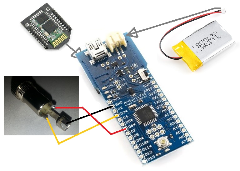
The jacket module is even simpler to set up than the bike module. The image below is a diagram for the setup of the jacket module. It is extremely simple as everything is socketed aside from the headphone jack.
![]()
You will need to hook up an FTDI module to program the Arduino Fio with the JacketModule.ino sketch from github. The USB port on the board is only used for charging the LiPo and powering the Arduino.
No changes to the sketch should be necessary provided you followed the wiring diagram above, but feel free to modify the wiring and sketch as you see fit for your particular design/needs. A fair warning, if you intend on altering the coding often make sure you make considerations to easily access the FTDI programming pins.
[I would include a picture here of it inside an enclosure but I have included an optional 3d printable case design and instructions down on step 4 and nobody likes redundant images.]
Operation:
Make sure the LiPo battery has been charged. The orange CHG light will light while the unit is charging. Once fully charged the light will go out.
Plug the headphone jack from the jacket wiring into the jacket module.
Turn on switch for the jacket module. The bluetooth module LED1 light will start blinking as it waits for the bike module to pair with it.
When the bike module pairs with the jacket LED2 will light up steady. From this point any blinking from LED1 is indicating communication with the bike module.
[INITIAL Testing: After first pairing, check communication by signaling both blinkers and triggering the brake on the active motorcycle to make sure the jacket matches the output. If something is backwards or not signaling on the jacket as expected check the bike module wiring to make sure the correct wires have been tied in with the correct bike light wires. If you continue experiencing issues feel free to comment on this project and Ill do what I can to help.]
Stuff the module into an inside pocket on your jacket and you are ready to ride.
-
3Step 3
Jacket Wiring, LED Setup, and Light Pipe Assembly.
I never took pictures of this process with the first prototype so I need to complete the second prototype and take pictures to use as visual aides along the way, I should have them up in another week or so. I may end up designing some nice 3d printed LED holders for mounting too.
First off we need to get the Light pipe set up. Measure the length of the light pipe and cut it into two equal length pieces. Press one end of the light pipe onto a piece of tin foil and cut out a small disk using an X-Acto knife. This disk is placed between the two segments of light pipe to prevent the signals from bleeding into each other from the opposite end, and act as a mirror to help brighten up the end of the pipe that lacks an LED. [In the future there are plans to experiment with dual LED terminated segments, along with additional pipe segments that can be programmed to operate in a different manner].
Cut an inch and a half length of clear heat shrink. Insert the Light pipe, aluminum foil disk, and other segment of light pipe. Center the aluminum foil disk in the middle of the heat shrink. Press both lengths of the light pipe and sandwich the aluminum foil firmly. Heat the heat shrink tubing with a blow dryer or heat gun(do not use flame as it could discolor the light pipe) to lock the light pipes and aluminum foil into position. Continue to apply pressure sandwiching the aluminum foil until the heat shrink has cooled.
Lay out the pipe on the back of your jacket in the configuration you see fit, making sure to keep the heat shrink tube centered in the middle of the jacket. Curves are acceptable, just try not to have any tight radiuses so the light will continue down the pipe well. You can get a bit creative here. The only point to remember is the more light pipe used, the dimmer the pipe will end up becoming towards the middle when the segments are longer than around eight inches(depends on curves and LED brightness).
Attaching the light pipe to the jacket is still a work in progress as far as trying to find the best method. Currently I am using some 100lb test fishing line and sewing it into the jacket about every inch and a half, then using super glue to lock the knot and seal the holes in the leather where the fishing line penetrates. This is not the easiest method since puncturing leather in general is a difficult process but it does work and I have not had any issues yet with it failing to keep everything together. I eventually would like to find either light pipe that has a sewable welt along the edge or some clear sewable hollow piping that the light pipe can be pressed into.
Locate an inner pocket in the jacket where you would like to have the headphone jack come out at. Next locate the two points where the light pipe terminates on the jacket. Determine the best path from each end of the light pipe to the pocket. You will need to route a length of 24 gauge speaker wire from each light pipe end into the pocket, I found using a piece of stiff wire to push from one end to the other and then using it to pull the wire through the jacket saves a lot of time and energy. Leave enough length on both ends for trimming, and to pull the jack out from the pocket to easily plug in the module.
At this point determine which legs of your LEDs are positive and negative to prevent issues and confusion as you solder up the wiring and resistors.
If you have standard resistors instead of SMD resistors, it is easiest to solder them into the headphone jack. Cut them short and solder one each to the left and right leg. Slide the headphone jack cover up the wires. Next slide a length of heat shrink up the wire coming from the right side of the jacket and solder the wire to the right headphone jack leg. Do the same with the wire coming from the left side of the jacket on the left headphone jack leg. Finally solder both ground wires from each side to the ground leg. Slide the headphone jack cover down and screw it in place. At the light pipe ends solder the ground and positive wires to each LED.
If you have SMD resistors it seems to be easiest to solder the wiring directly into the headphone jack, we will use perf board and create a mount for both the LED and resistor at the light pipe ends. Cut the perf board to approximately a 3x3 hole square. Solder the 4 legs of the LED in place, then solder the ground wire to the negative side of the LED. Next solder the SMD resistor down to the board at the positive LED end, and solder the positive wire to the SMD resistor.
At this point it would be a good idea to plug the module into the headphone jack on the jacket and test to ensure the LEDs are lighting as expected. You can do this by either connecting with the bike module and pulling the break/using the blinkers, or by connecting the jacket module over bluetooth to a computer and using the arduino console to send "HH\n" to the module(excluding the quotes).
Eventually I want to design some 3d printed LED holders for mounting that will hold the LED securely and capture the end of the light pipe, they will also provide some points for sewing down on the jacket as well. Until then I am using more heat shrink tubing. Cut an inch and a half length of black heat shrink tubing and slip it over the LED far enough to cover some of the wire as well, then slip the other end over the light pipe. Press the LED to the light pipe firmly making sure the pipe is centered on the end of the LED. Heat the heat shrink tubing with a blow dryer or heat gun(do not use flame as it could discolor the light pipe and damage the LED) to lock the light pipes and LEDs into position. Run a little superglue around the wire and heat shrink to ensure a watertight seal, the light pipe and heat shrink should seal up nicely by its self. Push any excess wire back into the jacket and then superglue around the wire to prevent it from pulling and damaging the LED and to seal the hole. Finally Run one last stitch of fishing line over the ends of the light pipe where the heat shrink is, and superglue from the fishing line back to the end of the LED within the heat shrink tubing.
I know the superglue concept does not sound as appealing on a motorcycle jacket as you would imagine, but it works extremely well with the leather. If you use a careful hand so as not to allow for drips the superglue is not noticeable in most cases. The fishing line can be seen slightly if someone is inspecting up close so aesthetically it is not the best but it works quite well without blocking any light emission from the light pipe.
Again, sorry for lack of images on this section, I will work to get some pictures made and added soon.
-
4Step 4
Optional 3D Printed Jacket Module Case
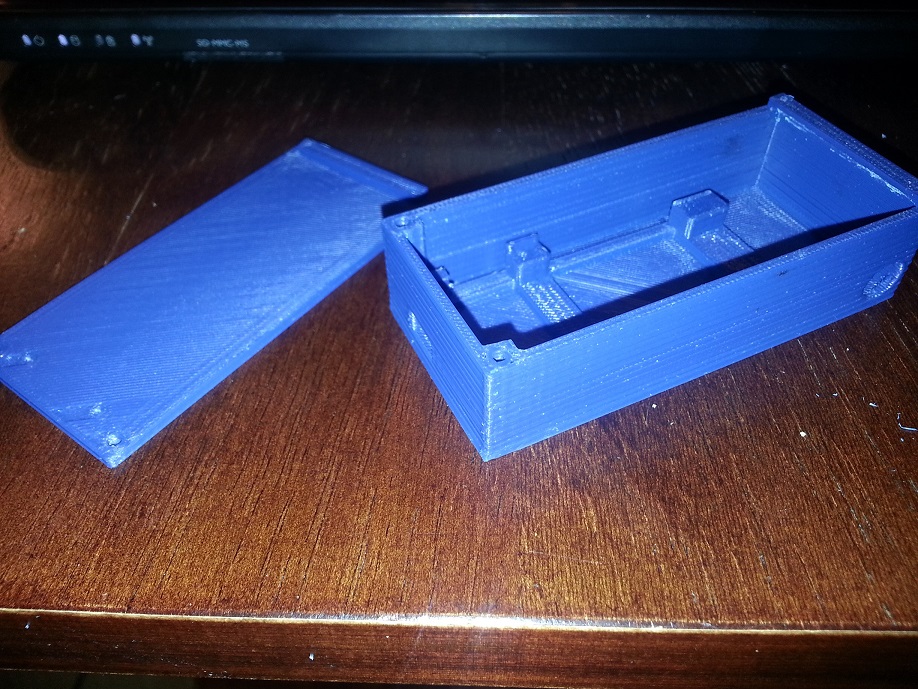
Download the Base and Top to the case and print them on your favorite RepRap OpenSource 3D Printer. It should come out looking similar to this(colors may vary ;) ):
![]()
The headphone jack hole may need to be cleaned up with a drill bit or X-Acto knife prior to screwing in the female headphone jack. Solder wires to the jack long enough to stick out from the case. Then solder the wires to the Arduino Fio as shown in the diagram from step 2. The LiPo battery has some electrical tape added to help increase the amount of insulation between it and the boards.
![]()
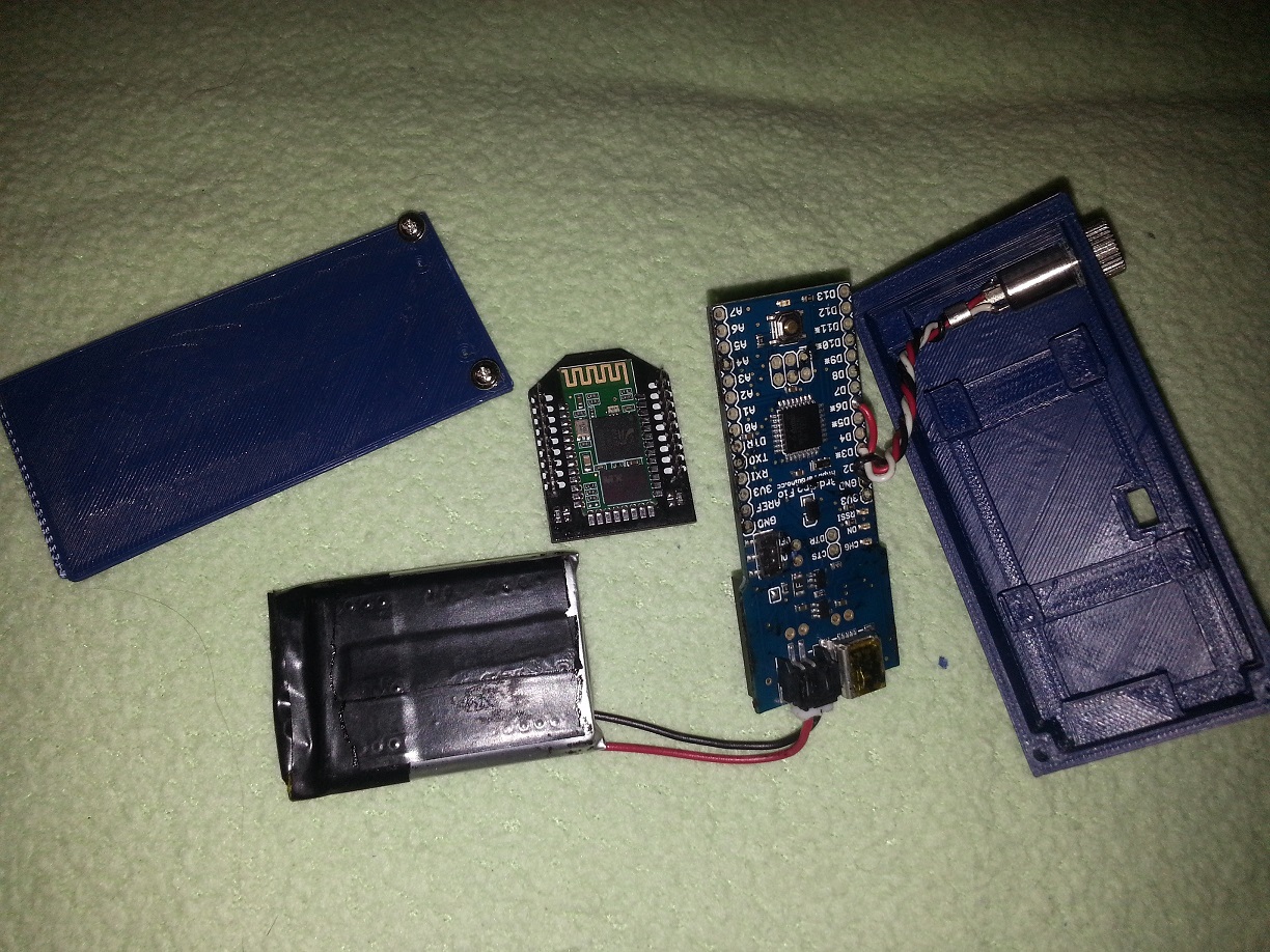
The image below attempts to show the process as it goes into the case. The Arduino Fio side with the actual components and sockets faces downward into the case with the sockets opposite the headphone jack. The case has risers and tabs to help position the Arduino Fio correctly but it is a friction fit the case is tight enough that everything stays in place just fine with the lid installed. The LiPo stacks in next and is partially sandwiched between the Arduino Fio and the Bluetooth Bee.
![]()
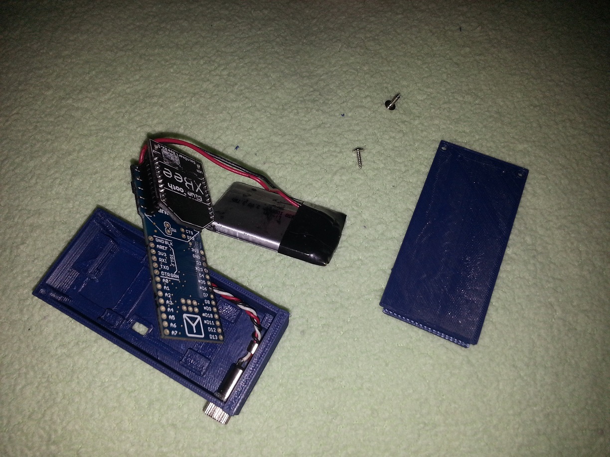
Below is it all stacked into the case.
![]()
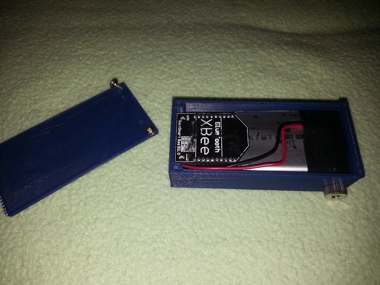
The lid on, screwed in place, and connected for charging.
![]()
The main items to note with this case:
- Its ugly.
- The USB port on the Arduino Fio is only used for charging. To re-program the Arduion Fio the Bluetooth Bee and LiPo will need to be pulled from the case to access the FTDI programming pins.
- The switch is recessed a fair bit. You will need something like a toothpick or bent paperclip to reach it. I had intended to design a printed slider for the switch but have not had time.
- The lid does have two very small holes located near the screw holes so the Bluetooth Bee LEDs are visible from outside the case. If your 3d printer is not heavily accurate for tolerance you may want to adjust the STL file to increase the diameter of the holes, or once printed just drill them out with a fine drill bit.
FireCoates
Motorcycle jacket that mimics signals using input from motorcycle brake and turn indicators for additional visibility.

Discussions
Become a Hackaday.io Member
Create an account to leave a comment. Already have an account? Log In.