 Peter G
Specifications:
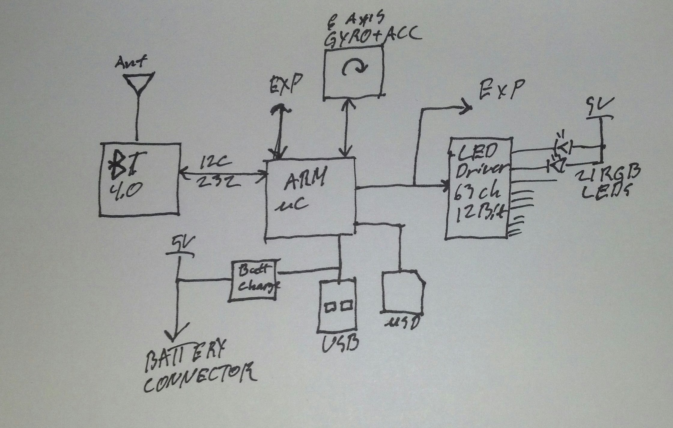
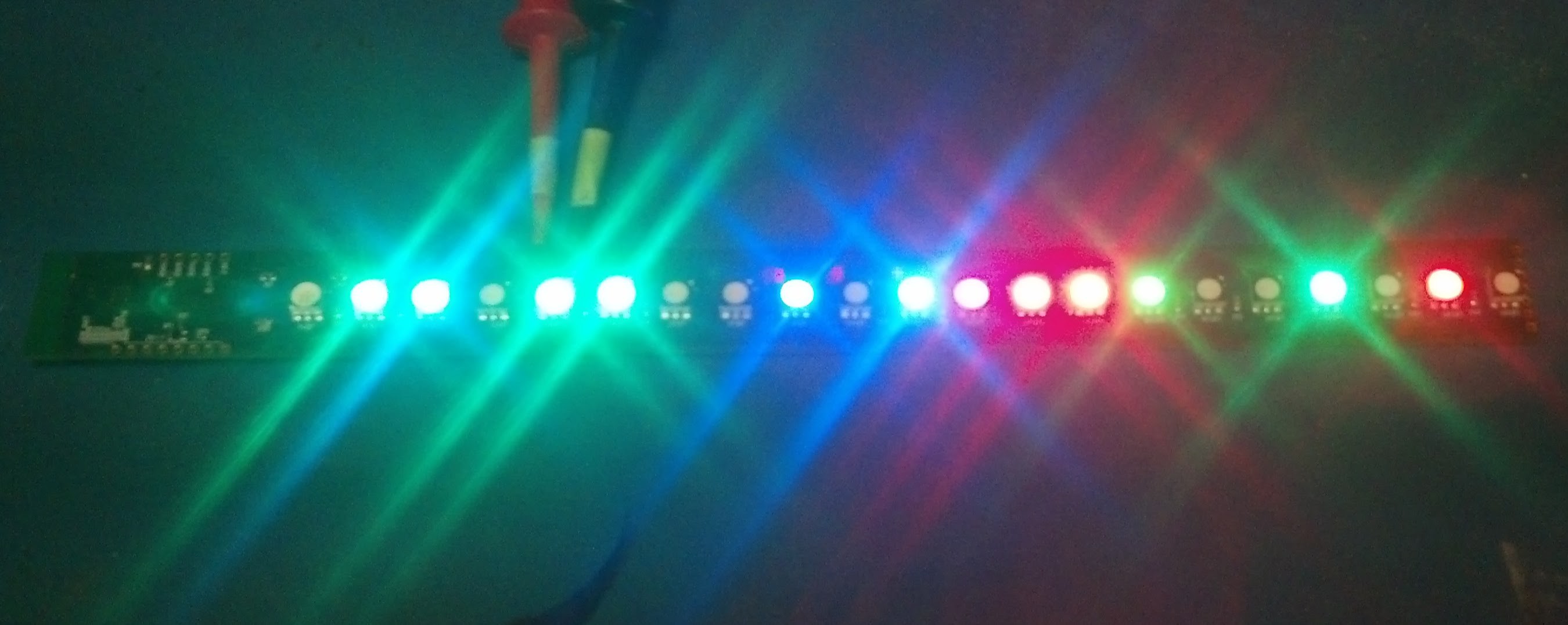
- 21 high brightness RGB LEDs.
- 6 DOF Accelerometer and Gyro for speed and position detection.
- 72MHz ARM M0 processor with 20kB of ram and 68kB of flash.
- USB interface with Lithium battery charging circuit.
- Bluetooth LE radio for remote control.
- General Purpose Digital and analog IO for interfacing sensors and whatever other circuits you may dream up.
- uSD memory card interface for storing animations and effects.
- Daisy chain-able to enable construction of arbitrarily sized POV display.
- Open source
Future improvements:
-Arduino compatible
Here's a professionally produced back of the envelope block diagram:
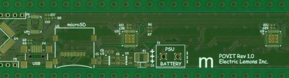
Schematic and PCB prints:
https://github.com/peggus/POVIT/blob/master/POVIT.pdf
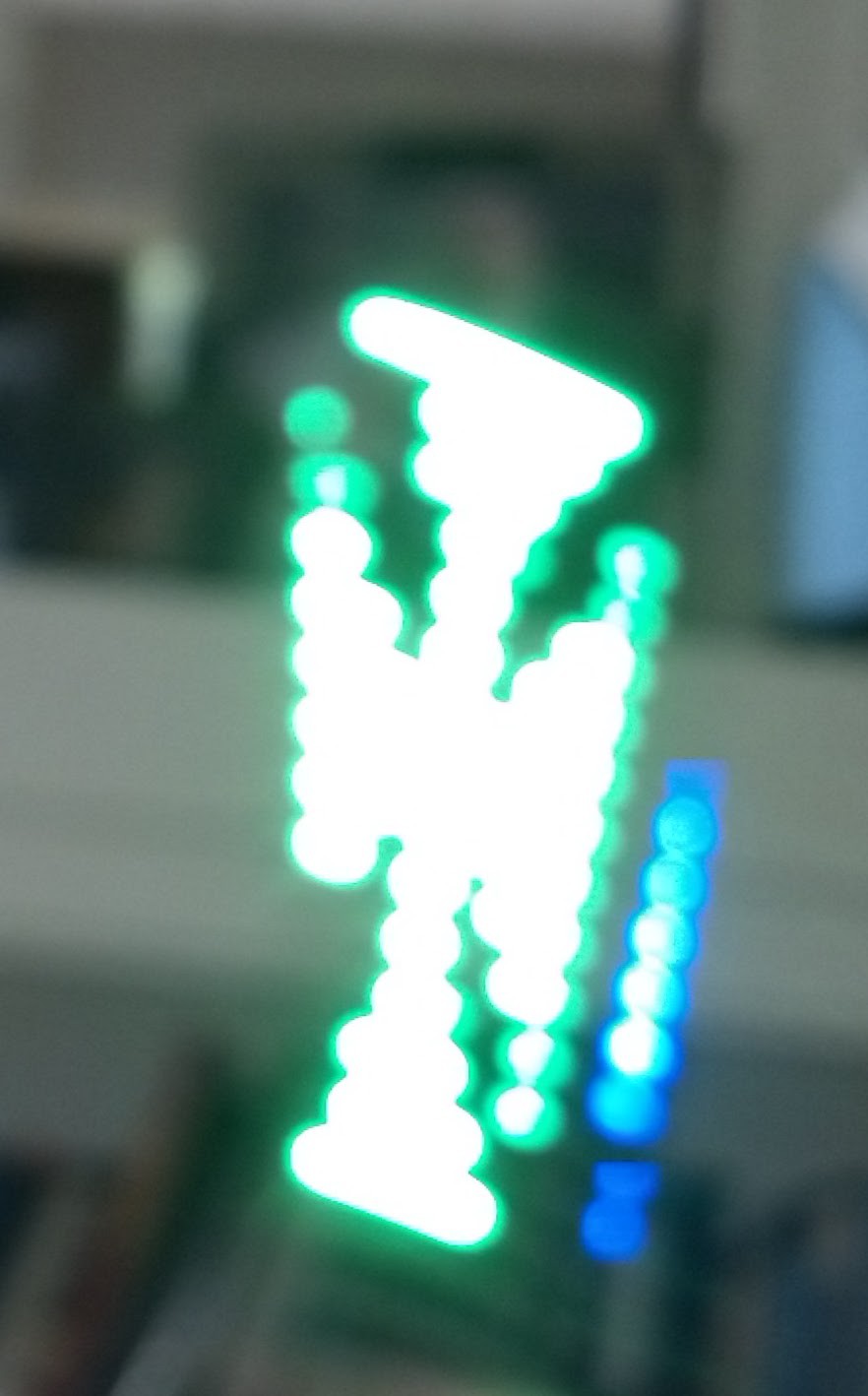
This is a very crude first software release. Mostly a jumble of test routines. It estimates the z axis angle based on gyro and accelerometer data and displays a bitmap one line per degree.
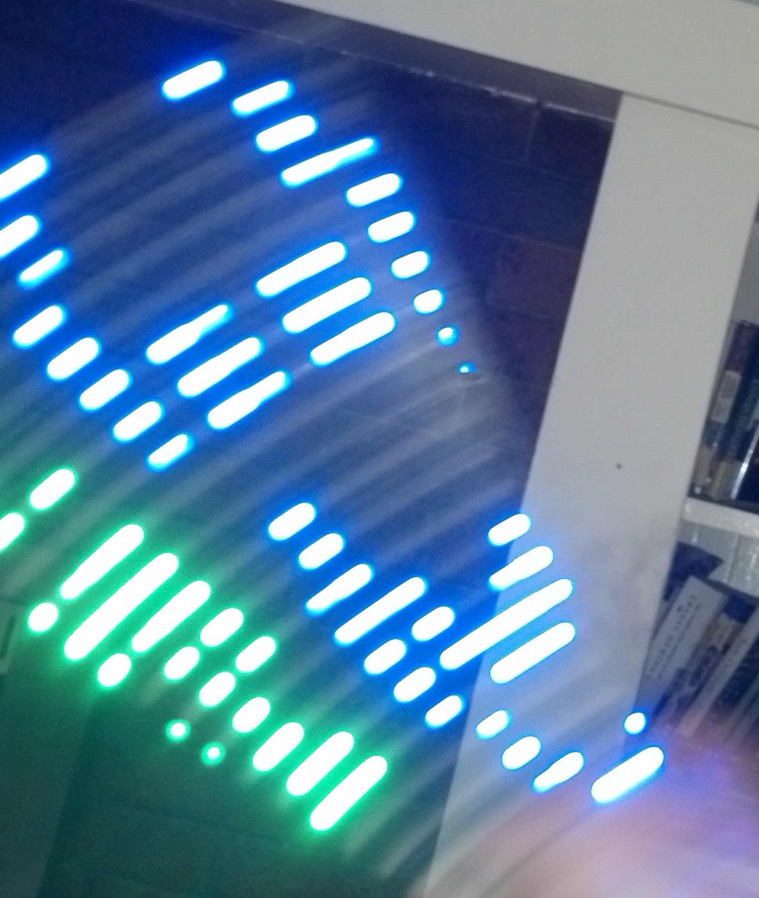 Smiley face
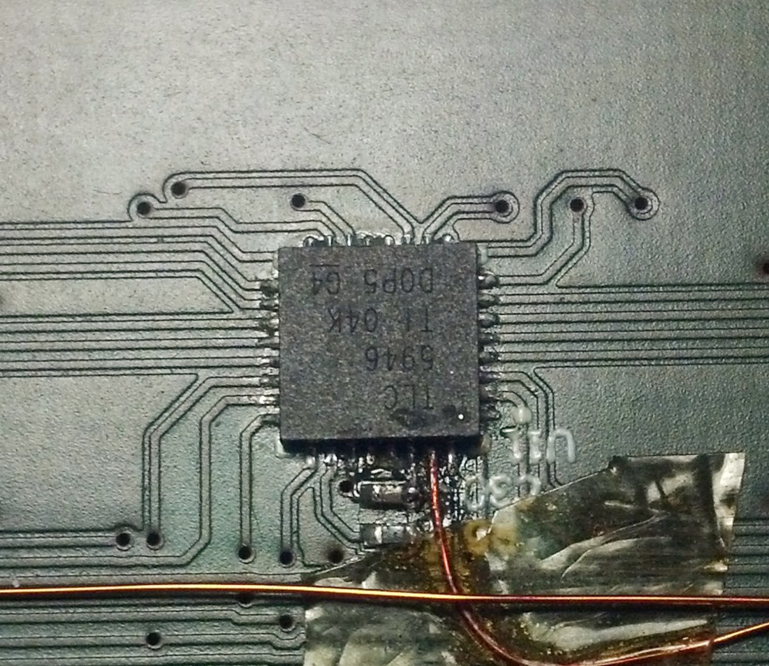
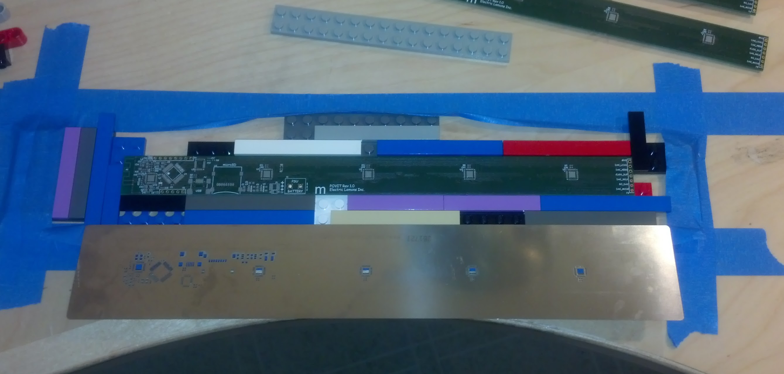
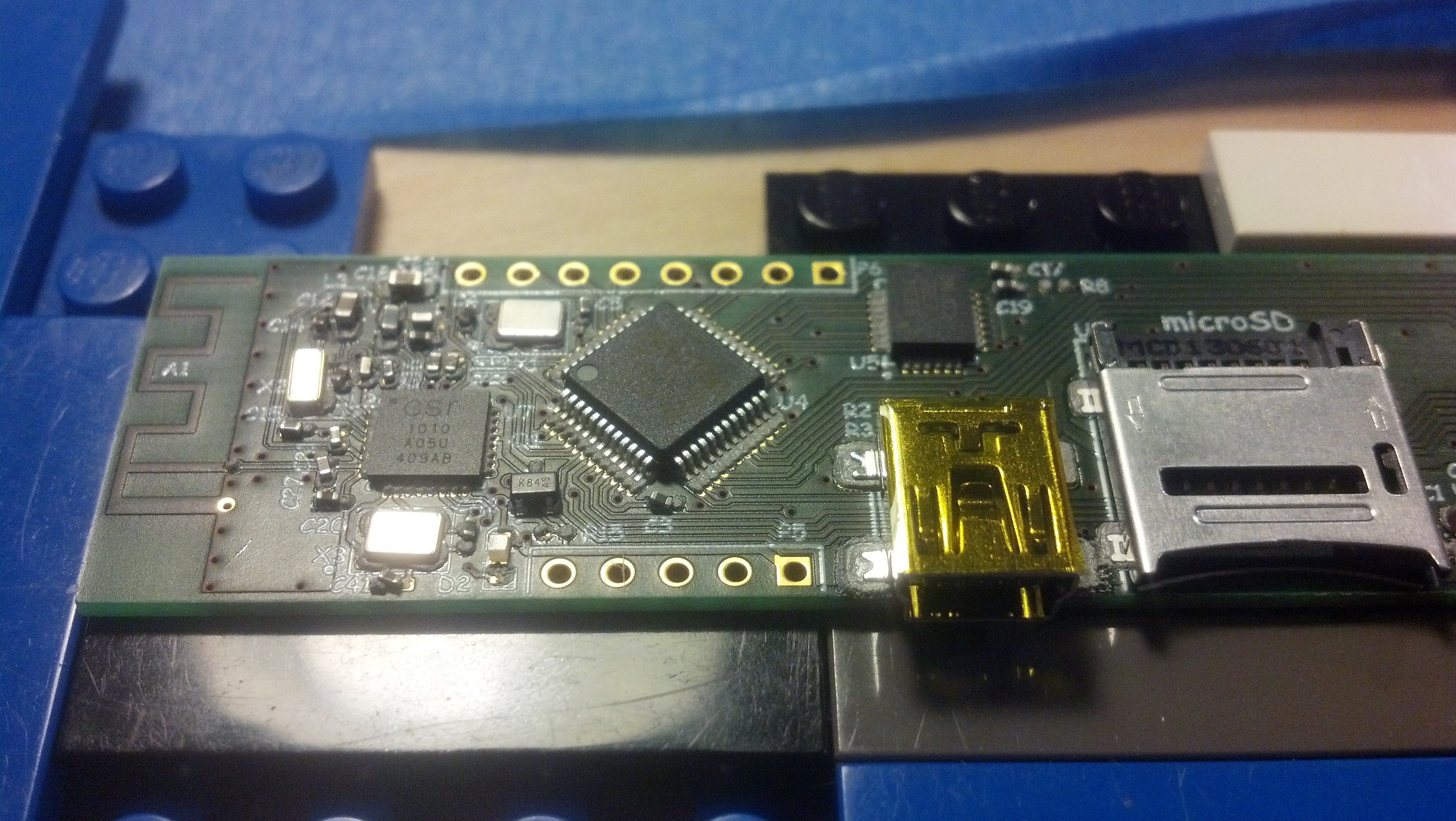
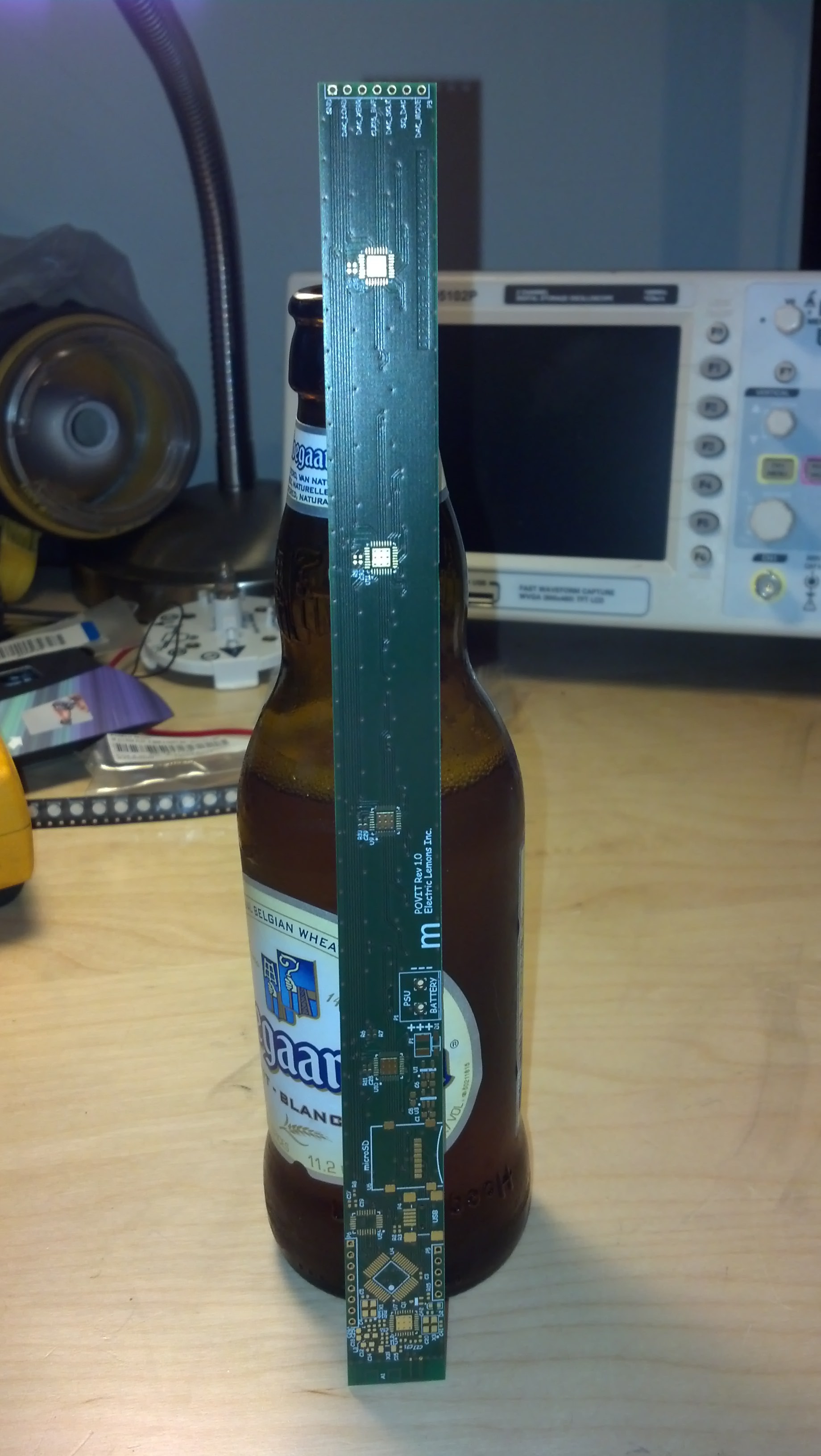
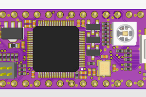
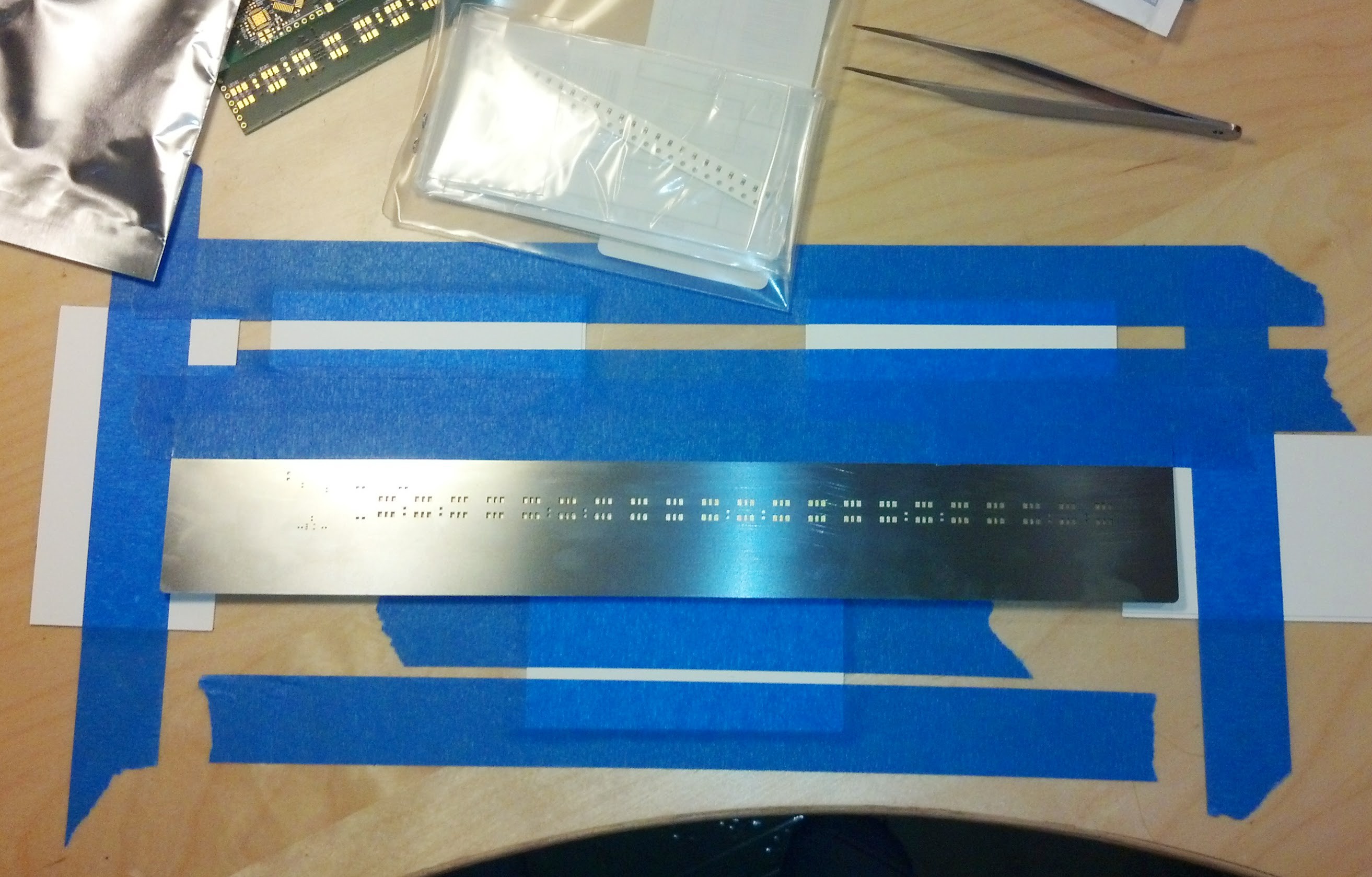 Stenciled
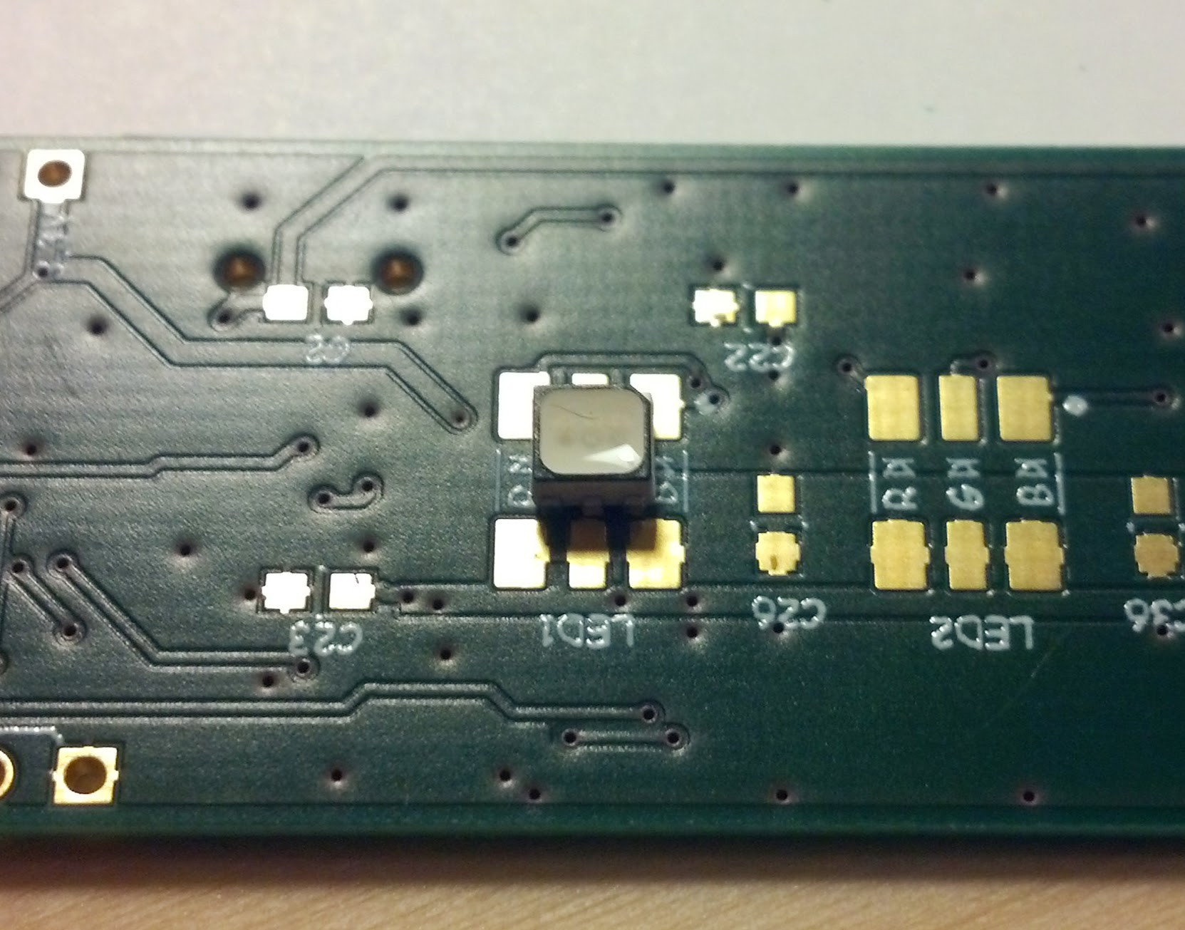
 Stuffed and soldered, one side anyway.
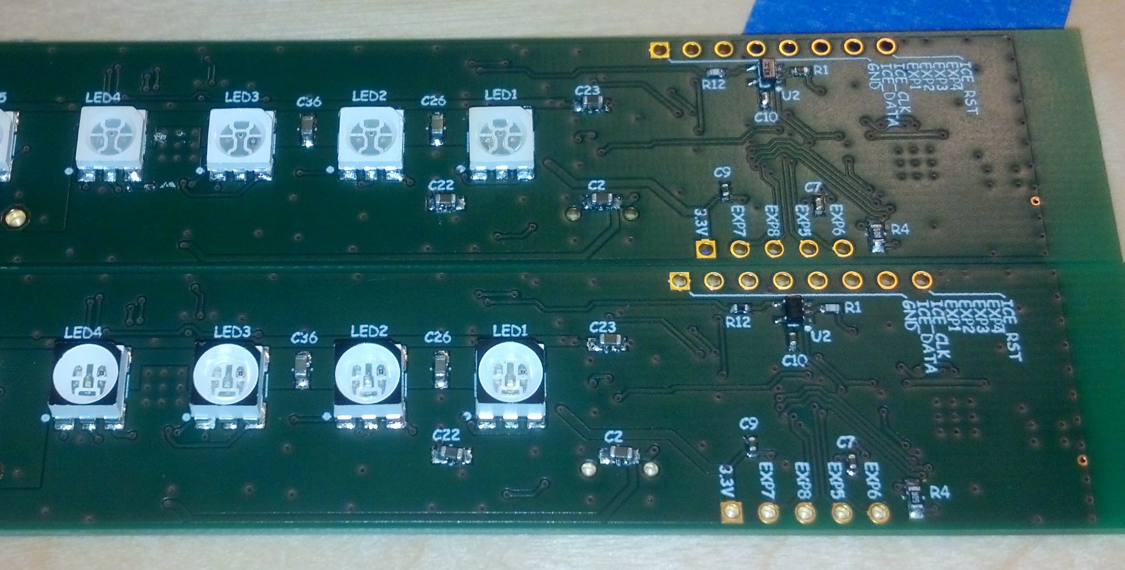


 STAR
STAR
 Clyde D. Corpuz
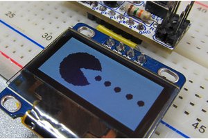
 Simon
Simon
 Jacob Still
very interesting, what gyroscope did you use for this?