 doctek
Probably the first important detail is that I am currently travelling and can't get to all the design files (like schematics and board designs) that I intend to post for this project. Most of the pieces are working, but still have to be "packaged" and complete software for the Teensy 3.2 must be completed. Enough excuses, I'll try for some actual meat here.
Never mind! I'm home now and will add as much as I can in the remaining two days!
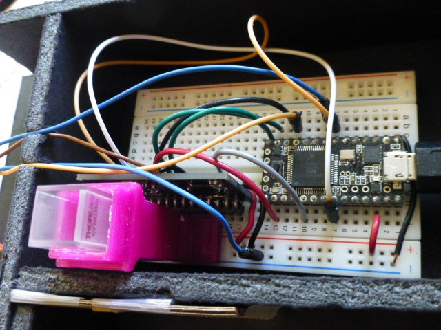
Actually, Teensy 3.0, 3.1, or 3.2 will work for this. Shown is a Teensy 3.0 because that's what I have handy.
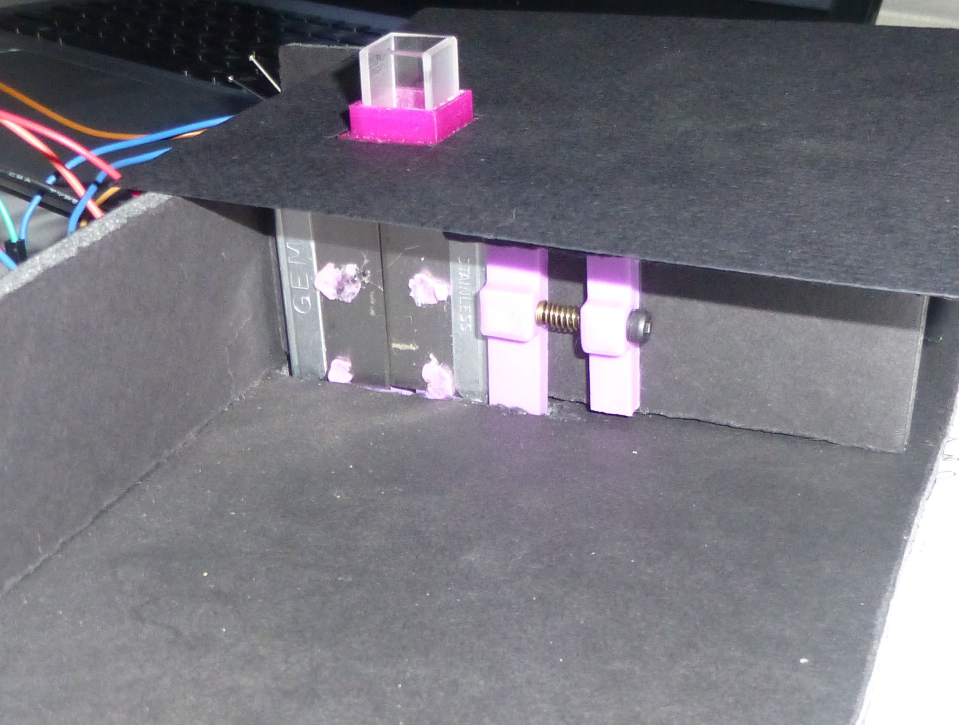
Here is the cuvette holder which I designed in FreeCAD and 3D printed. The FreeCAD source and stl files are now attached.
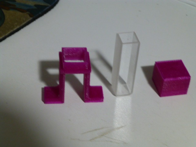
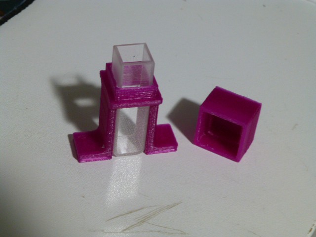
Right now, the cuvette fits a bit snuggly, and the cap doesn't fit all the way down. Easily fixed by changing parameters in FreeCAD.
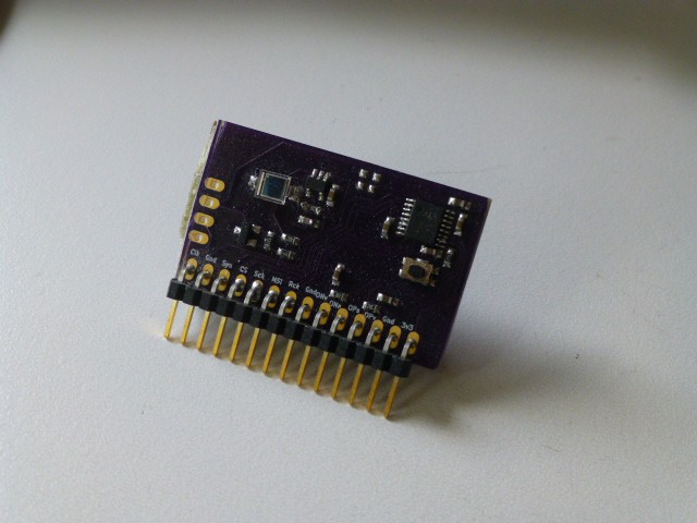
The lock-in amplifier, as shown above, (deserves some tutorial write-up, but wikipedia gives technical details) uses a newer part from Analog Devices, the ADA2200, as it's key component. A suitable photodiode and low-noise opamp (details to follow) complete the unit. This was originally designed for a fluorimeter, but will be used in the spectrophotometer first. A lock-in amp can be used in many other instruments as well, but let's focus. The Teensy is needed to configure the unit and gather the data from it to pass to a pc.
An Analog Devices AD8615 low-noise, low-offset opamp is used to amplify the output from the photodiode. The gain is programmable by changing the feedback resistor. Currently, I'm using a one meg resistor to provide one million x amplification. This is an area that will need tuning as the system is put into operation. Gains and losses throughout the system must be balanced for best performance.
The TLV431B provides the mid-range reference to the opamp. The system is designed for 3.3V, single-supply operation.
The 74LVC1G66 (note typo on schematic) is used to switch the LED that can be mounted on the Lock-In board. This LED was for initial testing only, but can be powered with 5 Volts. Switching is required to make the Lock-In amp work. The LED and the switch can be separated from the rest of the Lock-In if desired. Separation is best accomplished with a hack saw. Necessary signals can be jumpered using the holes provided.
The KiCAD schematic and pcb files are now attached. There is also a pdf of the schematic if you don't want to set up a KiCAD project. Please note that the guard around the sensitive input node is shown as a solid line in the pdf. This is misleading! It is shown as a proper dashed line in KiCAD.
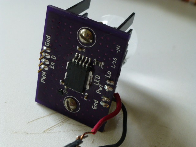
A STCS2A from ST Microelectronics is the constant current LED driver. It can provide up to two amps, but can be programmed for less - important since the max for the LED I'm using is one amp. The current can be modulated with PWM so that the lock-in amp works properly. The circuit board is designed to mount on a heat sink. Power is supplied from a 5V wall wart.
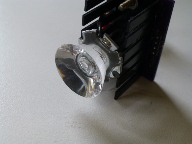
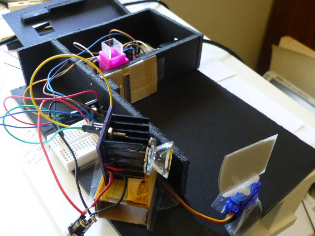
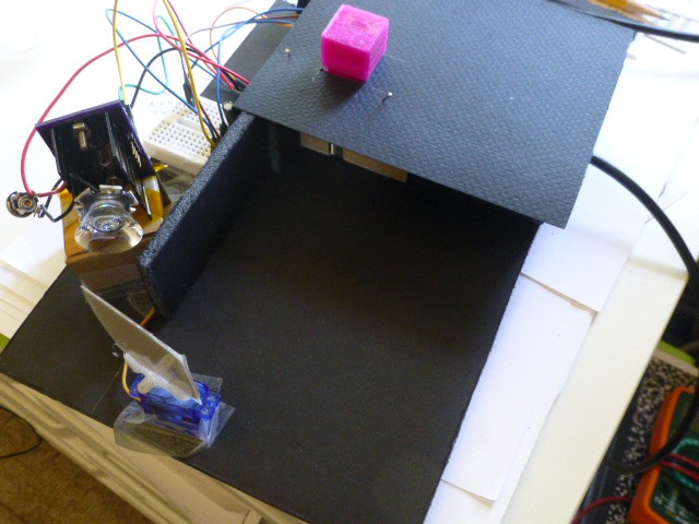
A key component of a spectrophotometer is the light source. A little research turned up a paper (reference to be added) showing that bright white LEDs could provide the broad light spectrum needed. See the parts list (soon) for the LED, the heat sink board, and the lens that I selected. The lens focuses the LED output so that most of the light hits the diffraction grating to make the spectrum that is focused on the slit and then on the specimen being tested.
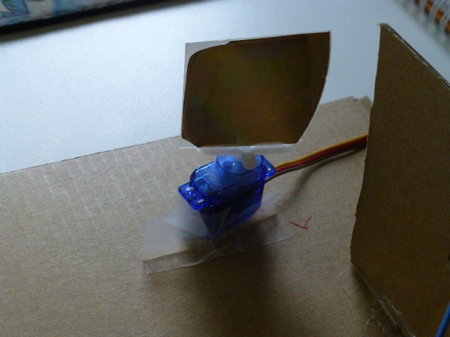
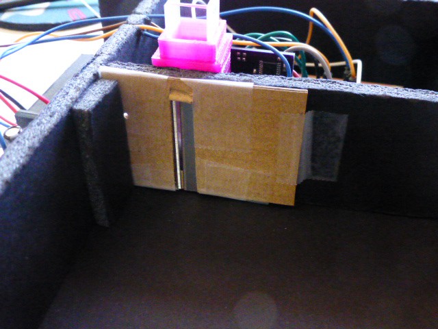
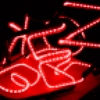
The bright light from the LED shines onto a diffraction grating to break into a spectrum (I'll try for a picture of it). An old DVD contributed a suitable grating. The servo moves the spectrum across a narrow slit to shine one color at a time on the sample being analyzed.

A sharp edged, narrow slit is formed by two razor blades. This slit can be considerably improved with a 3D printed adjustment mechanism. I'm working on that, but for the initial operation, this arrangement will do.
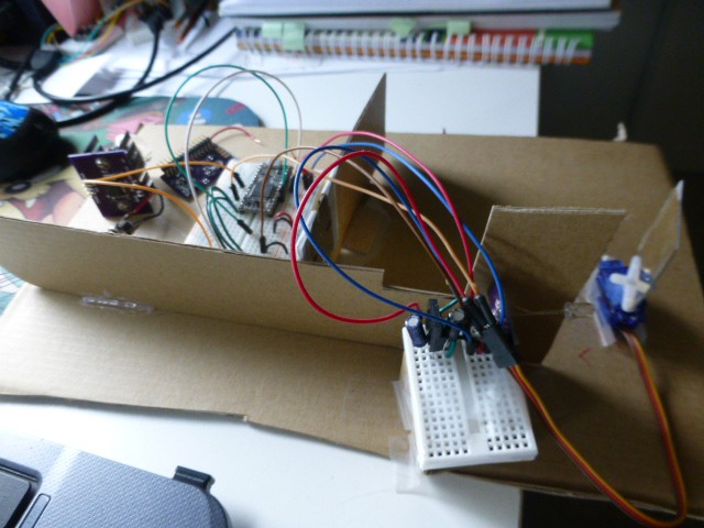
Here is a semi-helpful view of the system. The cardboard wall is to keep excessive light from hitting the sensor. You can see the...
Read more »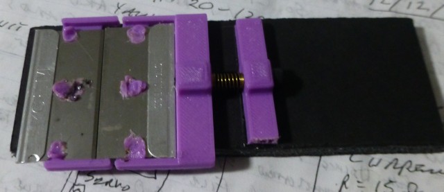


 Manuel Alfonso
 mircemk
 Kris Winer
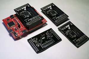
 helge
helge
I see that these posts are pretty old, so I hope you're still working on this spectrometer project. I wanted to ask if you were aware of the TSL2591 light detector? I've been using this device with an old Jarrell-Ashe scanning spectrometer that I salvaged from a discarded instrument and I've recorded spectra for LEDs, Laser Pointers, LED Flashlights and some really unique Electrodeless Discharge Lamps (EDLs, which were once a valuable device in Atomic Absorption Spectrophotometry). The spectrometer I have was designed to operate from about 1900 Angstroms to around 9000 Angstroms and the recorded spectra show some great lines in the 6000 to 8000 Angstrom range (from the Argon and Krypton fill gas in the EDLs). I'm also using the PLX-DAQ Excel macro software to collect and plot the data. Just a few suggestions that might help you as well!