 fl@C@
fl@C@
First off - you're going to want to hit the read more tag on this one if you're interested in this project...all the good stuff is toward the end... :D
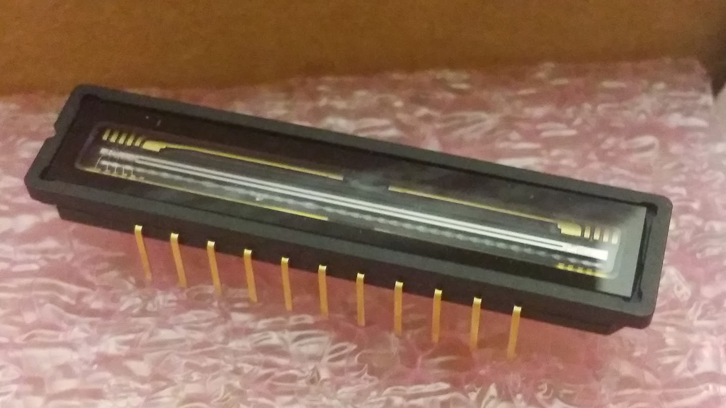

So... I got my delivery of the third Nucleo board from Mouser... A Toshiba TCD1304DG from eBay... and a few other parts that I ended up not needing...So, with that.. I set forth to get the CCD Array working.. I feverishly poured over every document I could find anywhere.. and there isn't much.. I tried to see if I could locate a development board, a prefab'd board that I could dissect...maybe a barcode scanner.. something... Nope. Nothing for less than $300 and certainly nothing I could get this month because of shipping..
A little backstory.. I had been mildly concerned about driving the CCD...how I was going to do it, etc.. I have no experience with CCDs, etc.. A bunch of searching turned up what I have said in previous build logs.. It seems the Toshiba and Sony chips are the most common used in spectrometers... the Sony chip is out of production... eBay has them, but it's literally weeks for delivery.. and someday they'll probably be gone.. not to mention they are mostly refurbished...... So, anyway.. Weeks have gone by that I've been flipping out stressed over getting the CCD up and running... I've been reading as much as possible, thinking, working on other parts of the project and so on.... Last night, I spent HOURS figuring out focal lengths and mirror angles for the spectrometer portion... and made a leap and ordered some optics from Edmund.. ok.. So, today..I figured.. I have enough parts to at least make an attempt with the CCD..
I sat down.. and went over some documents that I had previously found.. A site that sorta helped me gain my confidence and think maybe I had something to fall back on was this one.. Unfortunately he uses the Sony ILX511 and I couldn't get ahold of one for weeks.. After much searching, I decided to go to the source... The mBed website.. :) And after searching for 'ccd' there, one turned up! The mBed Pinscape_Controller is a project by Mike R. on the mBed site.. And oddly enough, he's using the TAOS TSL1410R which I did a writeup on thinking I might be going with that until I received some friendly advice from Marvin in the comments section notifying me that that chip was a bad option because of integration times... Thanks Marvin!!
So, after reading the writeup that Mike R had on the mBed site... I decided that maybe.....I would skip the ADC and other hardware that is normally used to control the CCD...and just drive it straight from the Nucleo.. There's only three clock signals... and the Nulceo has like 4 PWM controllers.. I figured it couldn't hurt to try... :D
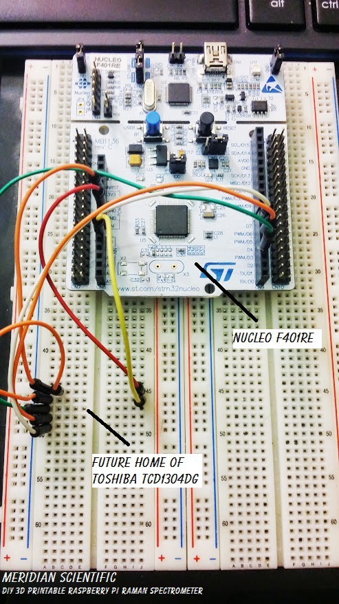
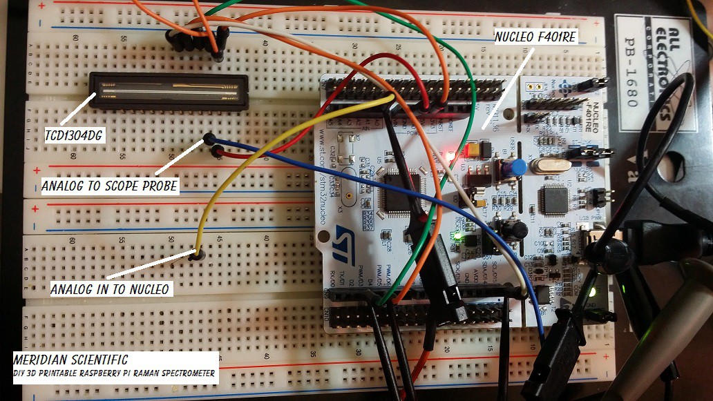
So, I sat down with the datasheet for the Toshiba TCD1304AP (which is almost identical to the DG except for packaging)... And study, study, study for a few hours... Then I built up the nerve..So I started off with just placing the Nucleo on a protoboard (it doesn't insert due to the dual rows of pins) with some jumpers to where the CCD would be...
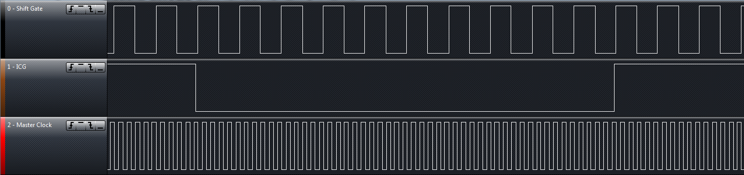
Then I starting some coding.... I wrote a quick program to generate the three clock signals that are required by the CCD..
This is my super simple starter test...emphasis on test since I know this isn't a great way to set up timing..but it worked for this proof of concept..
#include "mbed.h"

PwmOut shiftGate(PB_8);
PwmOut icg(PB_3);
PwmOut masterClock(PB_4);
AnalogIn imageIn(PA_0);
DigitalOut led1(LED1);

int main() {
    // set the masterClock
    masterClock.period_us(2);
    masterClock.pulsewidth_us(1);

    // set the shiftGate and have it start 15us after the masterClock - this will sync the clocks up so the shiftGate is going high just as a clock cycle is going high
    wait_us(15);
    shiftGate.period_us(20);
    shiftGate.pulsewidth_us(5);

    // set the ICQ clock and have it start 82.76ms after the shiftGate - this will sync the clocks up so the ICQ is going low slightly before the shiftGate is going high
    wait_us(82760);
    icg.period_us(80000);
    icg.pulsewidth_us(79990);

    // do something while it's having fun..
    while(1) {
        led1 = !led1;
        wait(1);
    }
}
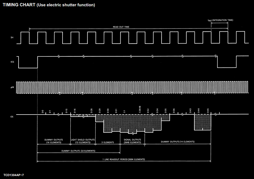
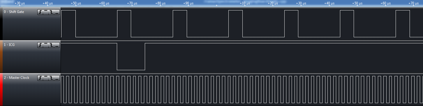
Here is the timing chart from the datasheet for the TCD1304AP.... I needed to match this as closely as possible.
My first attempt wasn't good...nowhere near what I needed to have...but it was at least generating three PWMs..
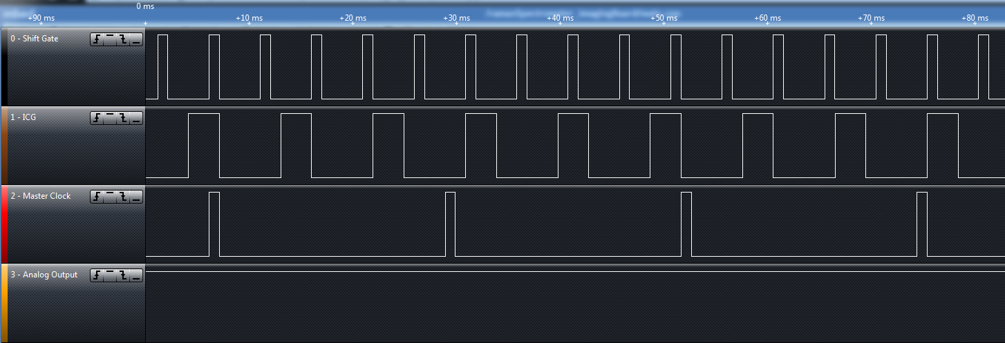
My second attempt was a little closer... But still waaaay off.. But it was getting a lot closer.. Not quite, but a little.
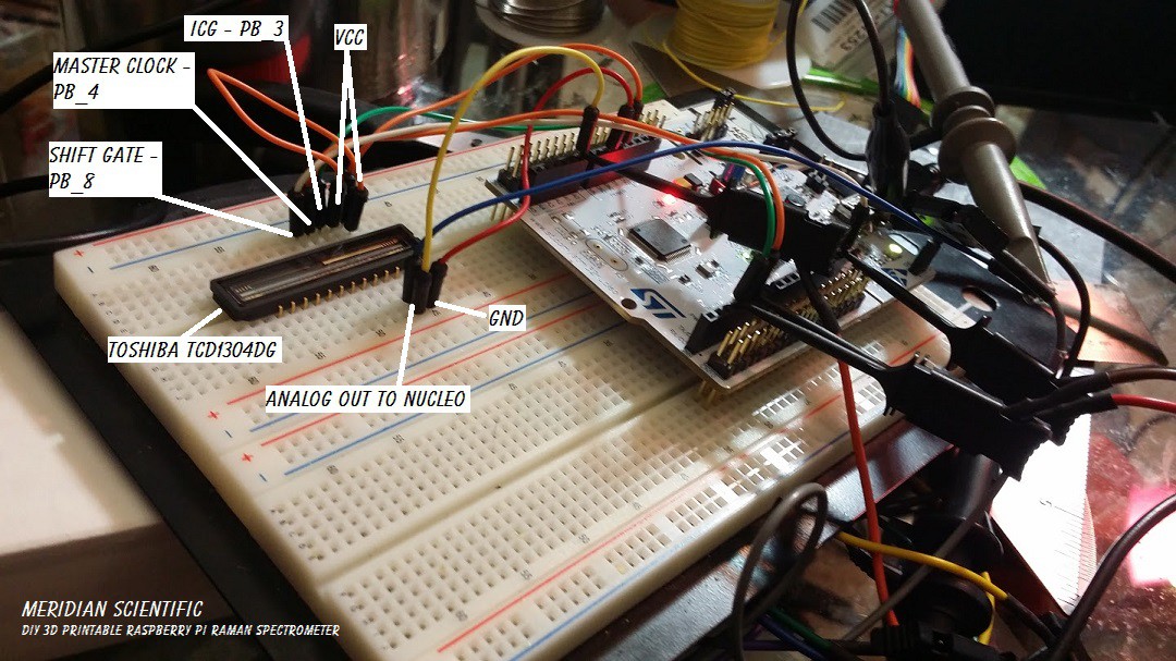
At this point, I was ready to insert the CCD in and try out my clocks...
Double check and make sure all the pins are going where they should be......
And you have to excuse me.. I've been writing these logs after like 12 hours of working on this every day and I'm usually falling asleep when I'm writing... But here we go... This diagram shows how I have it hooked up for now...
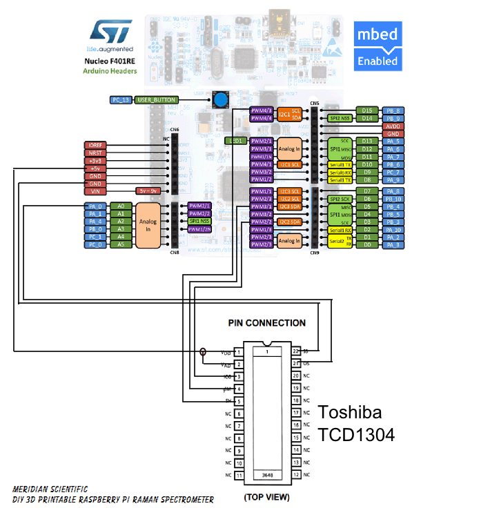
The Nucleo has a 12bit ADC... I figured that is good enough for my initial testing... As far as how fast it is.... I have to double check that, but I'm not entirely sure it's that critical since I won't be pulling at any high frame rates...
And so.. after MUCH time of going around in circles with the timing... trying to get it just right... testing, changing, trying it again... I hit the money...
With this, suddenly the scope signal that was kinda working and kinda responsive to light but totally like an old tv out of sync.... Straightened right up and looked like what you would expect.....
This is a scope capture from the CCD with my hand covering it to make it dark... (It's the red line)
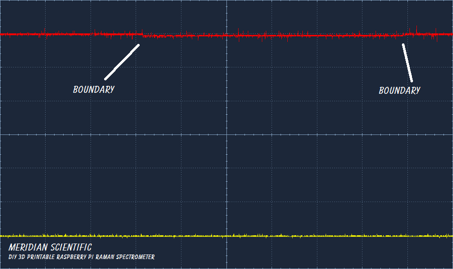
This is a scope capture from the CCD sitting in the room with just ambient light hitting it...

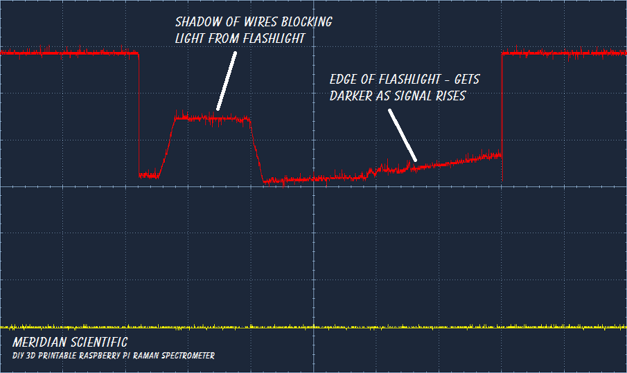
Here, I shined a flashlight and the shadow of some of the hookup wires blocked an area of the CCD....
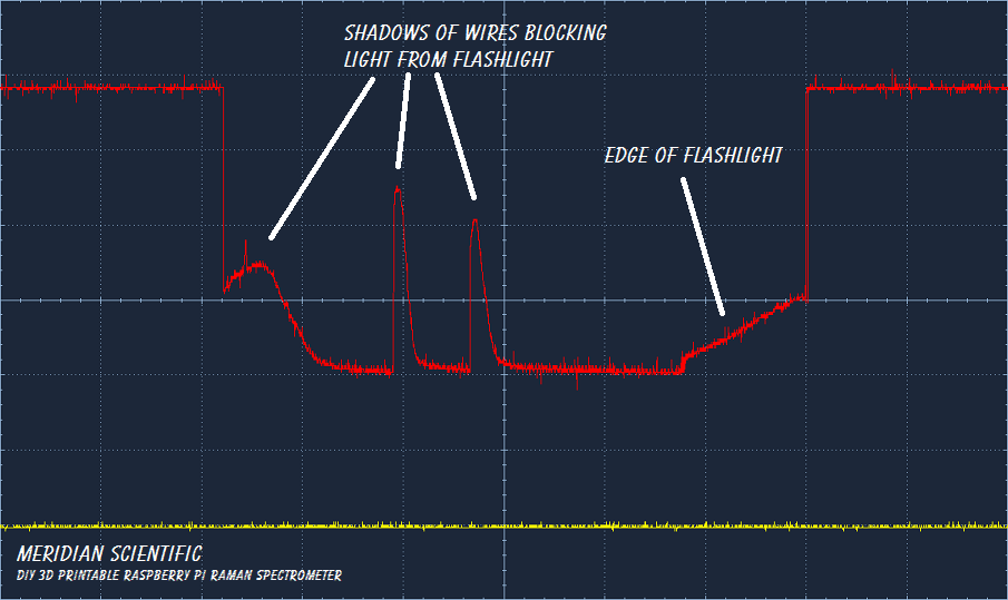
Another angle with the flashlight and more than one wire blocking the light...
So... I have a video of the whole thing working to... I am waiting for it to upload and process... then I will update this post with that as soon as I get up tomorrow... =D
Next step.....Add a better ADC, do some more testing... See if I can clean up the signal... although I am surprised how clean this came out considering it's on a breadboard with hookup wire...
Anyway... Let me know what you think! I'd love to hear it!

Discussions
Become a Hackaday.io Member
Create an account to leave a comment. Already have an account? Log In.
thats a good project. congratulation. you know, i made the same project, i used a FPGA device. I get the same result as you. i realy have a doubt. the first video that i found about this CCD sensor was this https://www.youtube.com/watch?v=ut9LfQmaYkU. In that vide you can see the same behavior, except that the measure of voltage looks inverted repect with our behavior. what you thing about it?. you think that he gay has the line voltaje inverted? or we have something wrong in our designed?. well, i'm so exciting for found someone that explain how to implement the TCD1304
Are you sure? yes | no