 EK
EKFor first step of the robot we decided to start working on is the Z-Axis Carriage sub-assembly.
We ran into some problems along the way, but iterated on the design to get it to its current working state. There are still additional problems remaining to be solved and the feedback system to be implemented.
Read more for our prototyping adventures!
Materials
Pieces are all 3D printed in ABS plastic.
Screws are 6-32 3/8”. Stand offs are used instead of hex nuts because we had more of them on hand.
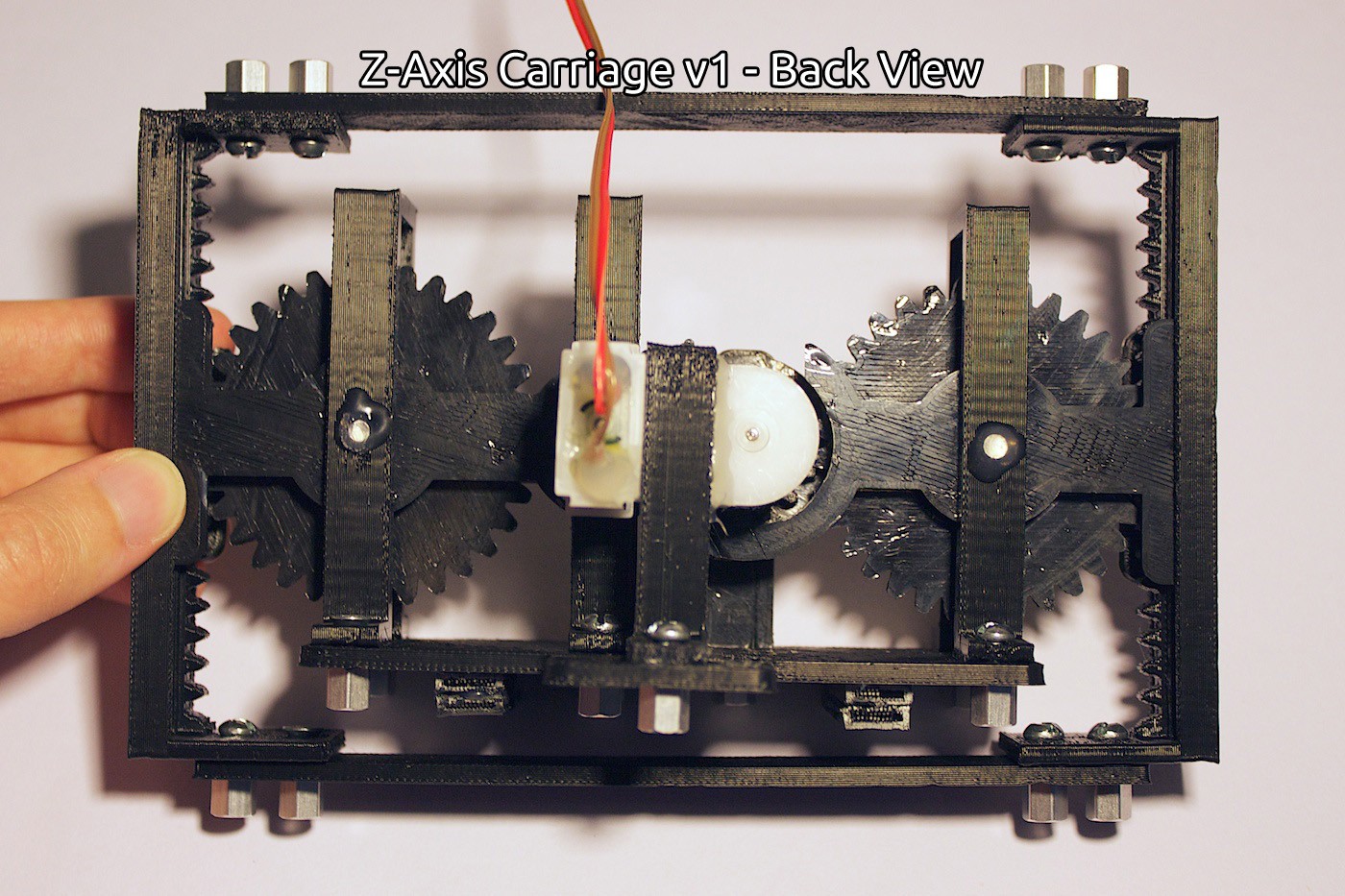
4x Rivets for the gear spindles. 1” in length and ~1/4” in diameter.
Hot glue is used for keeping the rivets in place, and the motor mount piece attached to the motor.
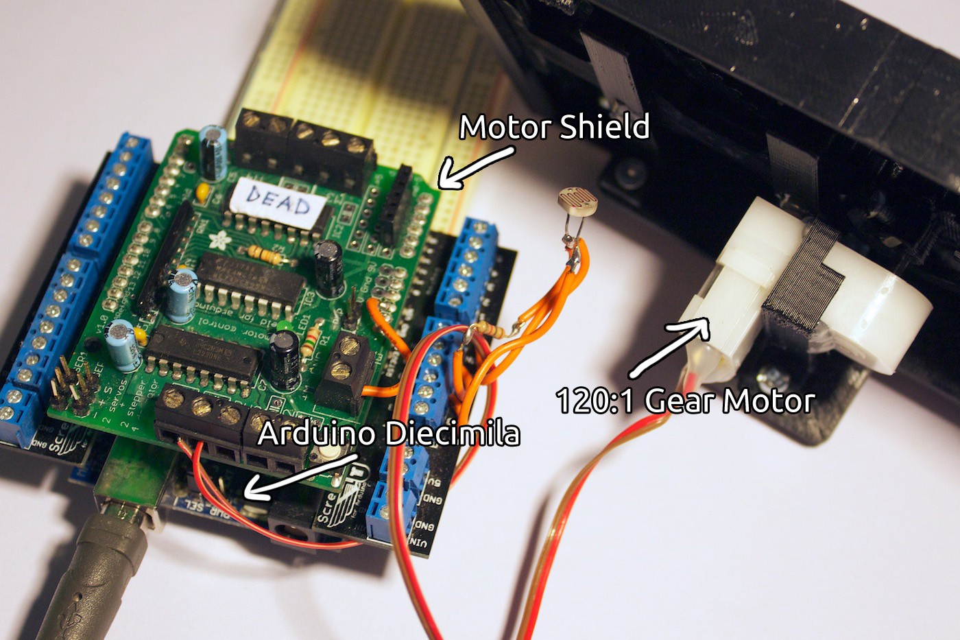
Motor is a 120:1 gear motor. Reason for choosing this one is it was one that was in my box.
Current Design
In action:
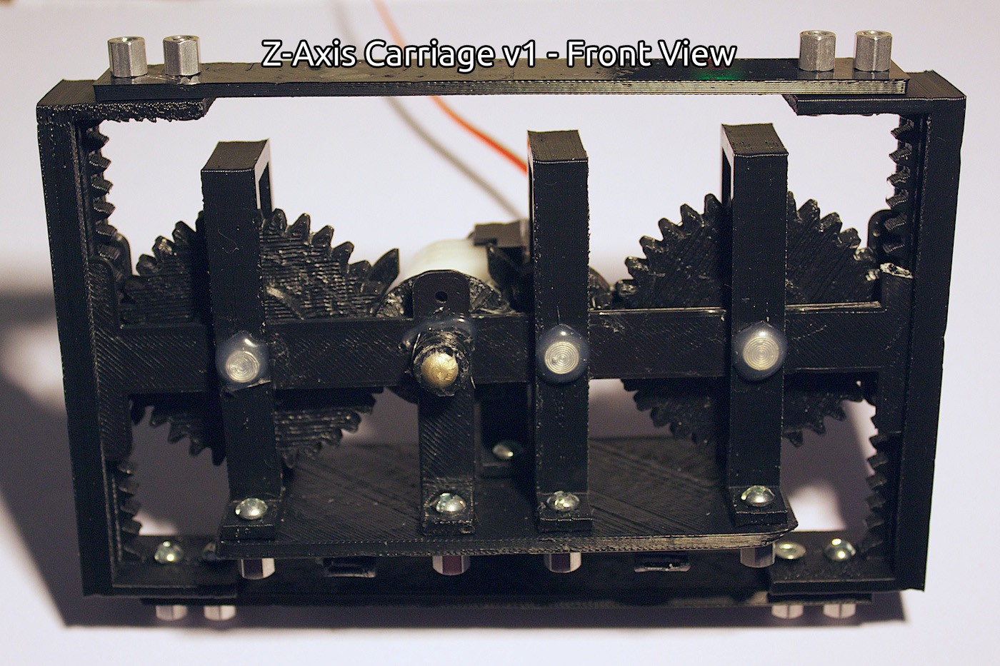
Front View:
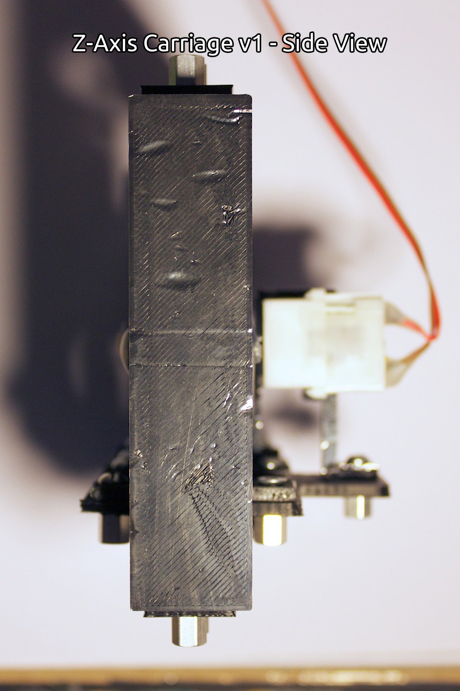
Side View:
Back View:
Electronics:
Prototyping
We started out by creating all of the pieces in CAD (Autodesk Inventor) first, based on the drawings.
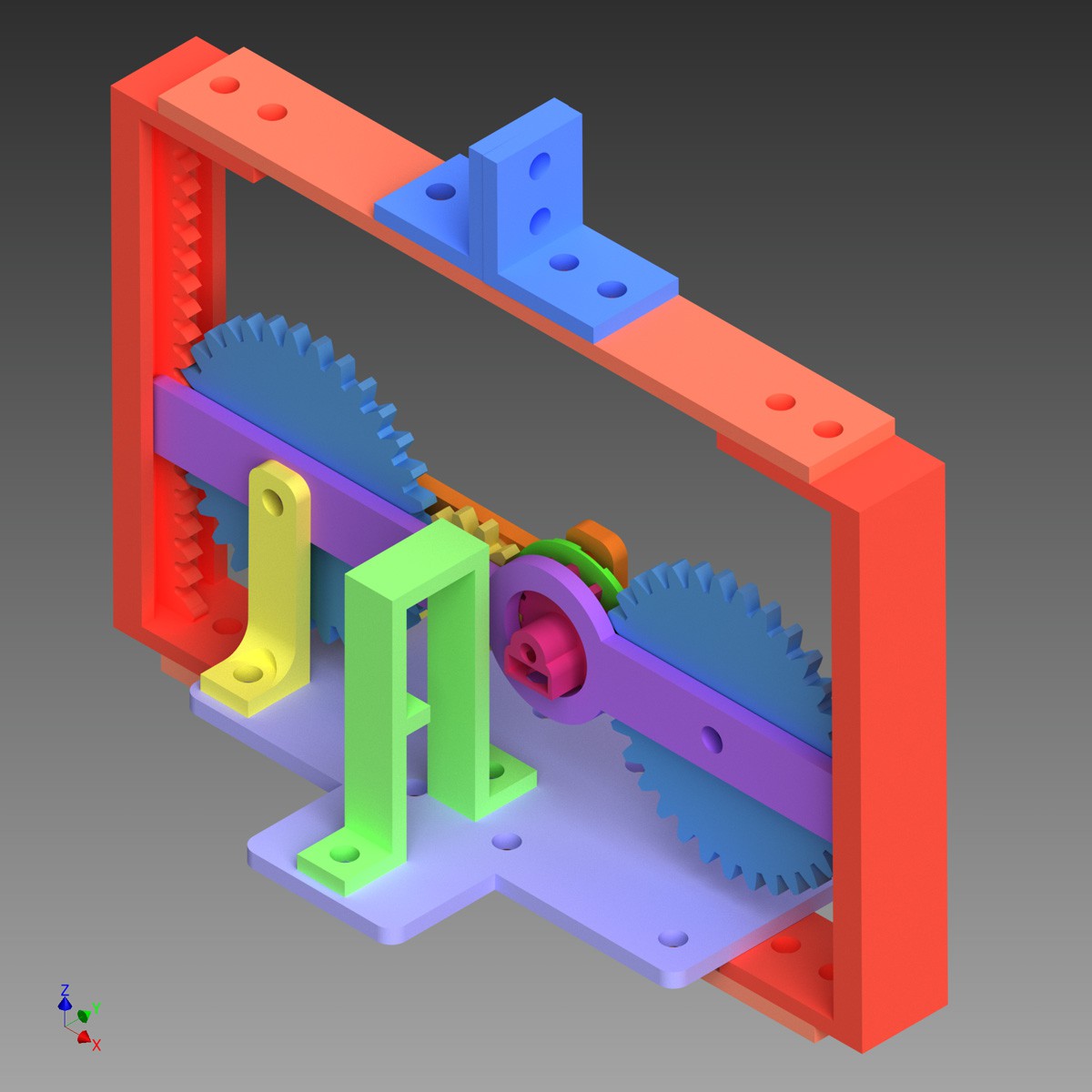
We printed the pieces, making some adjustments along the way. Eventually we finally had an assembly put together of the gear set, the inner and outer supporting bars, and the bottom plate.
Then we ran into the first problem. The gears kept angling inwards, preventing them from meshing properly.
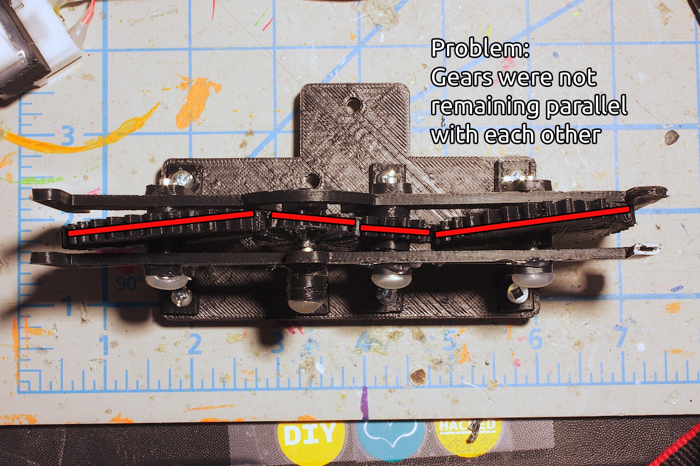
We fixed this problem by increasing the diameter of a circle extruded on the top of the gear, and the same idea with the inner bar.
We also made the vertical stands that are holding up the bars and rivets for the gear set into clips. This kept the entire gear set more tightly together.
The gears now stay parallel to each other and no longer tilt wildly out of place!
After testing the gear set, sometimes the gear teeth would slip. The drive gear would either move the pinion gear, or move the idler gear, but rarely both at the same time.
This was our next problem to solve.
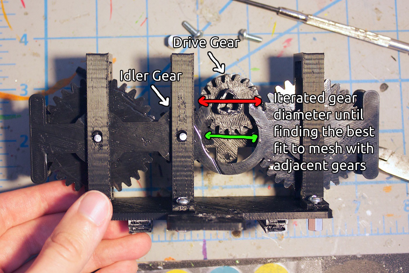
The gears were generated using this feature called ‘Design Accelerator’ in Inventor. It is very handy, and produces nice gears that perform well even when 3D printed. We increased the diameter of the drive and idler gear (they are both the same size), iterated on this, and eventually found the goldilocks size.
The drive and idler gears now mesh perfectly with their adjacent gears!
After testing this out for a little while, we noticed something bizarre with locking in the gear set to the two racks. Sometimes the bar attaching the two racks would need to be longer or shorter than previous, even though nothing much has changed.
We went back and forth on this problem for quite a bit. The gear set would move up and down the rack quite well, but then sometimes it would just stop. It was weird.
Finally we noticed something- the rack pieces are arced!
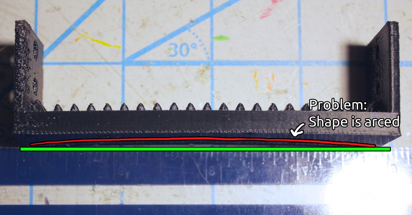
Here is a closer view of this:
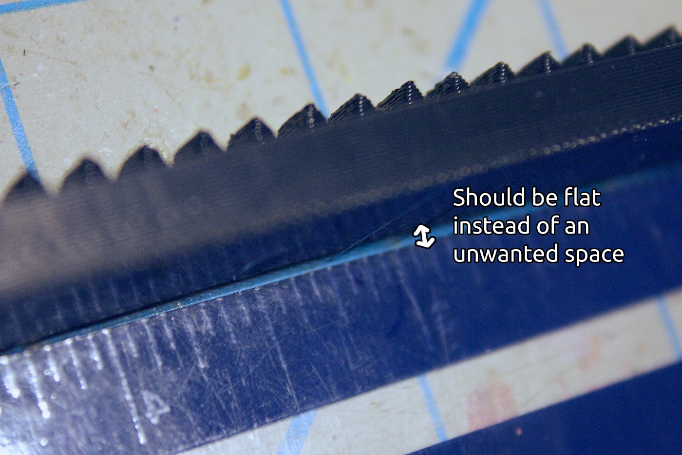
The rack piece should be flat. It would mess up if it wasn’t flat, because there would be varying degrees of pressure placed onto the gear set, which may cause it to not work. This is different than warped 3D prints, where warping is due to a malformed first layer or an issue with the build platform, or inconsistent heating during a print.
The reason why it is arcing, from what we have come to understand of 3D printing, is because the ABS is trying to stay attached to each of the printed layers. Each ‘strand’ on the long sides of the piece pulls upwards.
There is no room for the strands to be relieved. If there were spaces in the first few bottom layers, it would prevent this from happening.
So this is where we are at now. We have to work on a way to make this piece not arced. But we don’t want to design it to be flimsy, where it could bend when in use. Which would sort of be like the same problem, but reversed. We’re going to start out with the spaces idea and see where this leads.
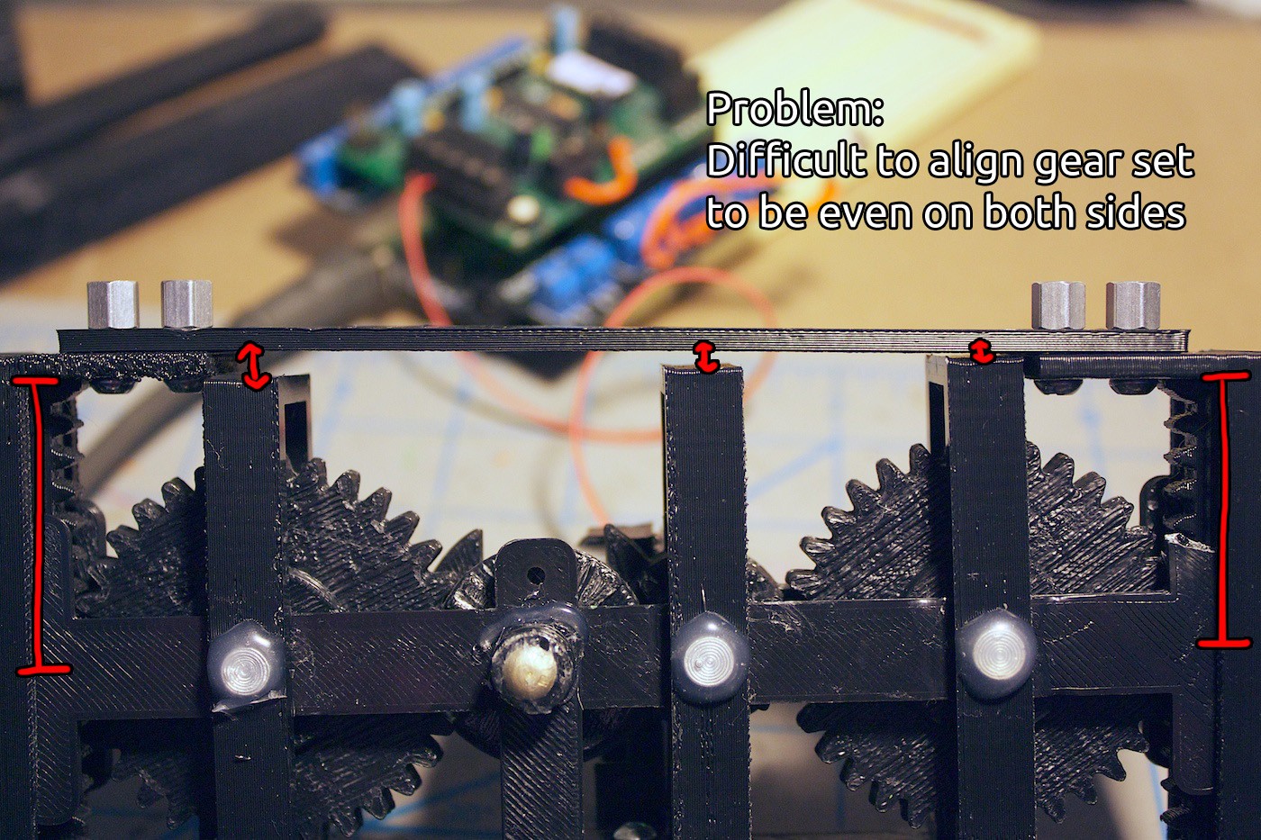
Here is another problem to be fixed in the upcoming revisions. It is difficult to align the gear set when sandwiching it between the two racks. Need to come up with a way to solve this.
Moving forward, there is the encoder disk and LDR to play with. This will require some tinkering to get it to work properly and semi-reliably. It will be interesting to see how well the feedback system will be able to work to hold the position of the gear set along the racks.

We’re not sure if the motor will be strong enough to press down with the knife to cut an object. The sensory feedback from the encoder can a little help with this. We could command the motor to be constantly driven, giving more force than if it were released, and thus applying pressure to the knife. Until we receive feedback that the position of the gear set has moved. We will have to see how it works out during tinkering and go from there. :)
Lessons Learned
It seems a lot of building things that move has to do with being able to restrict the movement in the directions other than the one it is moving in. This was an interesting lesson to learn when trying to keep the gears parallel to each other.
We also learnt that even if a shape is flat in the design, you have to pay attention to the fabrication method and materials used. Now that we have realised this, we can update the design to compensate for the arcing of the ABS!
Thanks for the comments on the discussion page. ;)
Also worthy of note, Cyberlane wrote a thought-provoking question about knifes, cutting angles, and rotary blades. We’re planning a larger post on this topic, so stay tuned!
If you have any questions or ideas that maybe we haven’t thought of, don’t hesitate to leave a comment! It might be helpful to us in the long run.
Until next time, making gears spin and learning new things!
Discussions
Become a Hackaday.io Member
Create an account to leave a comment. Already have an account? Log In.