 EK
EKWe advanced further into the build of this sub-assembly. Now the Z-Axis can slide along the racks, and we started creating the DIY encoder.
The most challenging part of this update was getting the DIY encoder set up to show different readings for the dark/light stripes.
We also solved the existing rack warping problem.
Read more to see all the details.
Rack Slider
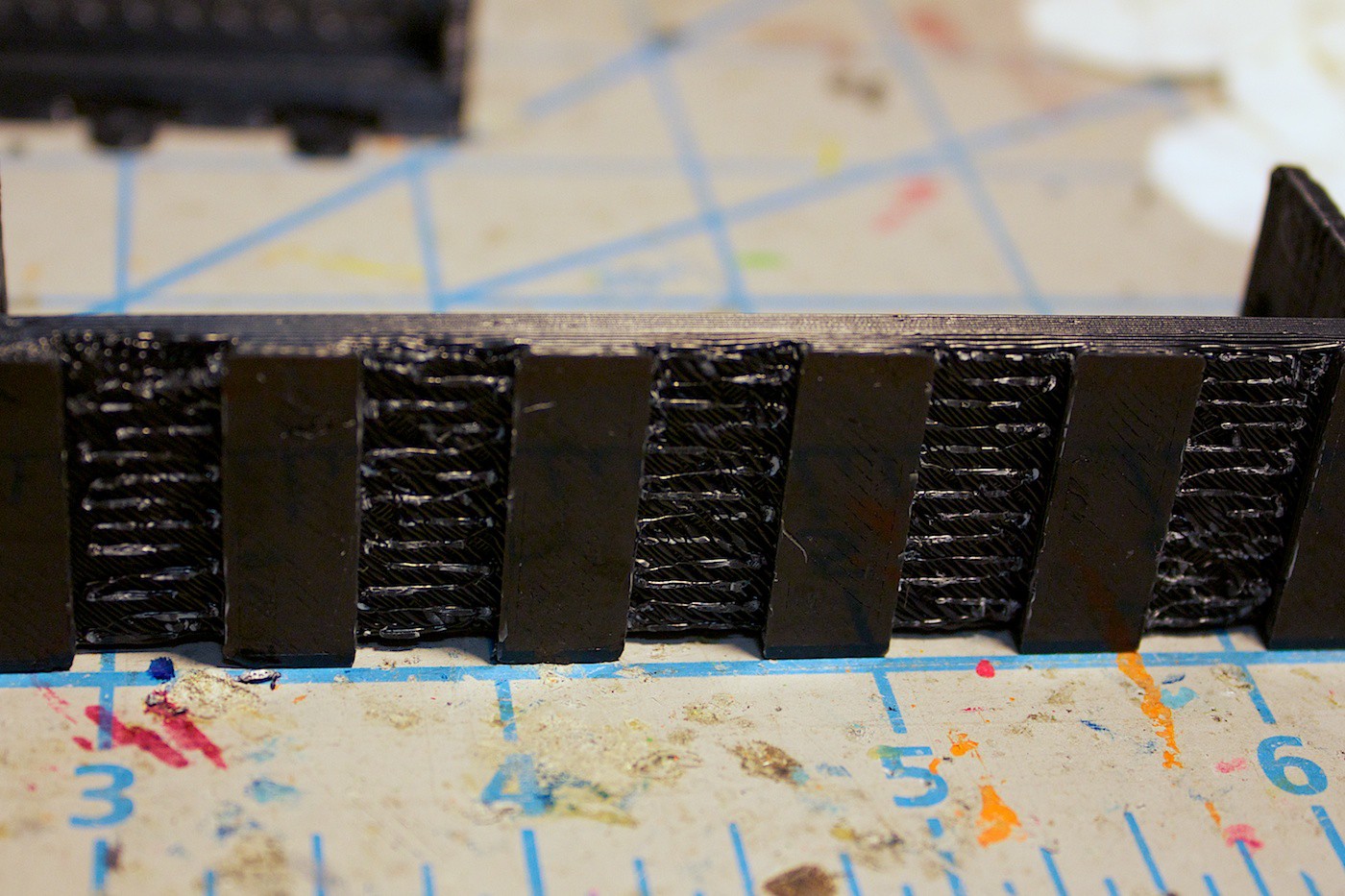
From last update, we noticed the rack slider pieces were warping after being printed. Our first guess at trying to alleviate this problem was to include ‘spaces’ along the bottom of the piece.
The way this design works is by cutting 3mm rectangles into the piece. Another rectangle is nested inside of its outline- but with its length extending beyond. This new rectangle is extruded to be two layers thick. Our 3D printer’s layer thickness is set to 0.3mm.
Since the piece will be printed with supports, the two-layer rectangle helps these supports adhere to something. If we did not have the rectangles the supports have to try to adhere to the build plate, usually resulting in unreliable print results.
Here is how it turned out:

After removing the piece from the printer, you can remove the two-layer rectangles and clean the supports away.

This is what the end result looks like. It is no longer warped like our previous piece.
We then tested the new racks with the gear set, and it works! The gear set no longer gets stuck at the middle, and it can slide smoothly along the entire rack.
Hooray! Another problem solved!
DIY Encoder Intro
The next thing we wanted to make is an encoder. We need to know some sort of position of the gear set along its racks. This feedback is useful both for driving the motor, and in case the gear set starts to slip (imagine if it’s trying to slice a burnt steak).
As it is right now, we are currently using time to drive the motor to certain positions. This can be problematic if an error occurs, such as the motor mount being stripped from the drive gear, or the gears slipping, or the pinion and rack slipping.
An encoder can solve this problem by being able to keep track of how many ‘ticks’ the drive gear has turned. A ‘tick’ is a change from dark to light, or vice-versa.
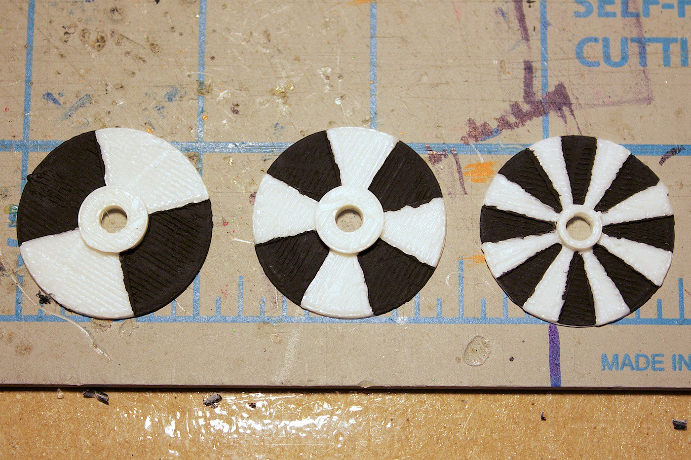
The way our DIY encoder works is by using a small 3D printed disk, in white filament. Black paint is then added to the alternating grooves. The intervals of the ticks will depend on how well your system works. We found that the most reliable solution was to go with the 4 intervals – each tick is 90 degrees. We’ll discuss how we figured this out later.
There is a white LED that shines on the disk. The idea being here that it will provide enough light to eliminate the effects of the ambient light.
A light dependent resistor is inside of a tube, pointed at the disk to see if the light is dark or bright.
The problem with DIY encoders is that it takes a bit of tinkering to get it set up to the point where it is reliable. We had some fun prototyping to find a way that works. Here’s how we did it…
DIY Encoder Part 1
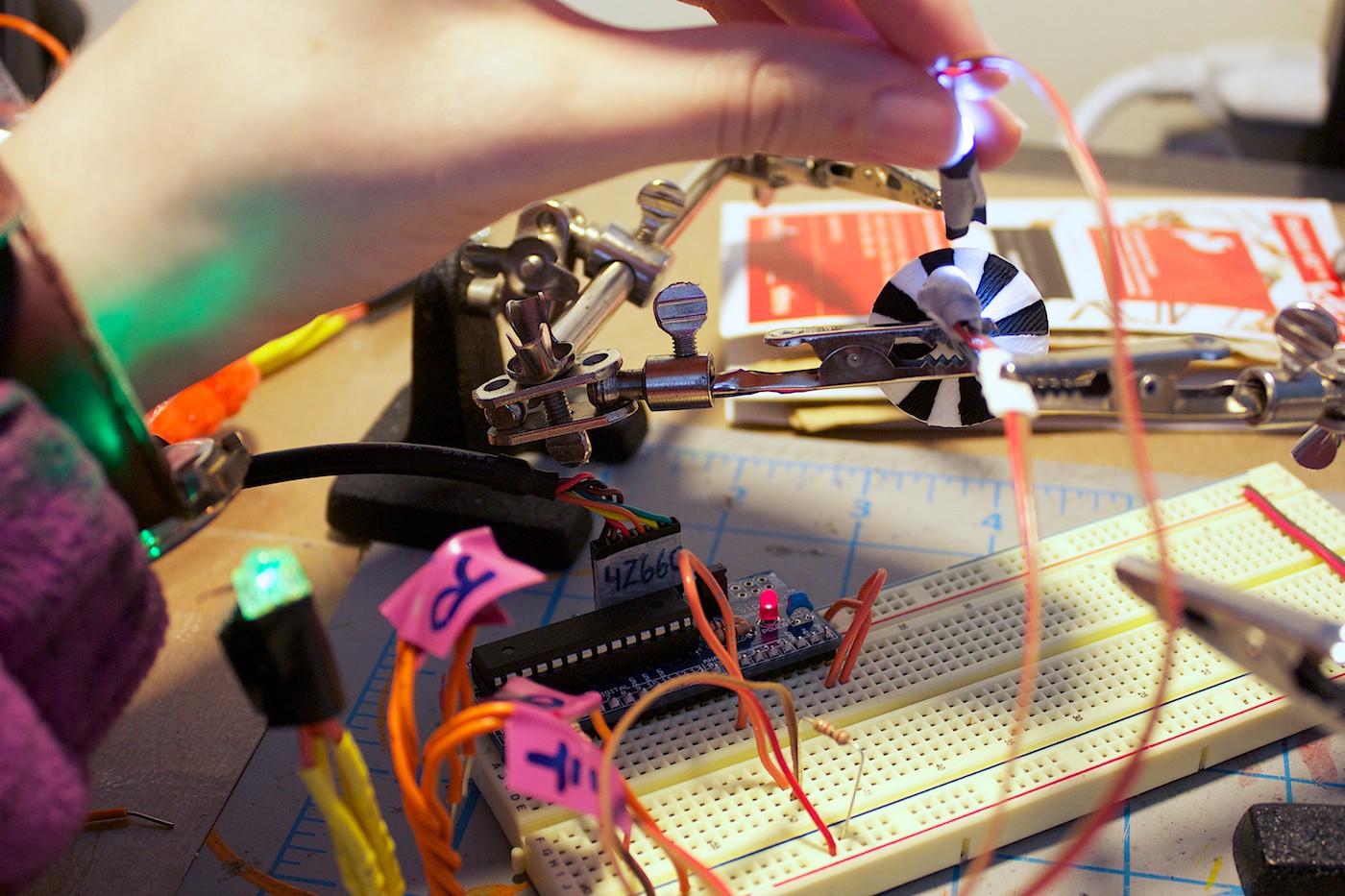
The first step was to set up the encoder disk and LED. We mapped the value of the LDR to the green LED (in the bottom left corner of the photo). By spinning the disk (slowly) and pointing the LDR at it, we could see if the value would change by the green LED getting brighter and dimmer.
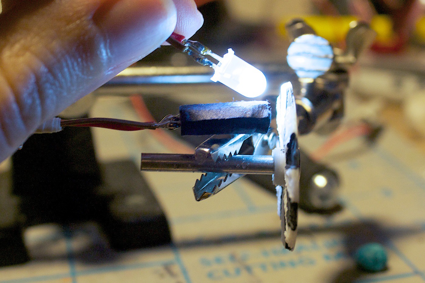
We tested holding the white LED at various angles, and at what distance to hold the LDR. We then designed and printed a mount for these. Here you can also see that we were experimenting with a tube on the white LED to make the light more focused.
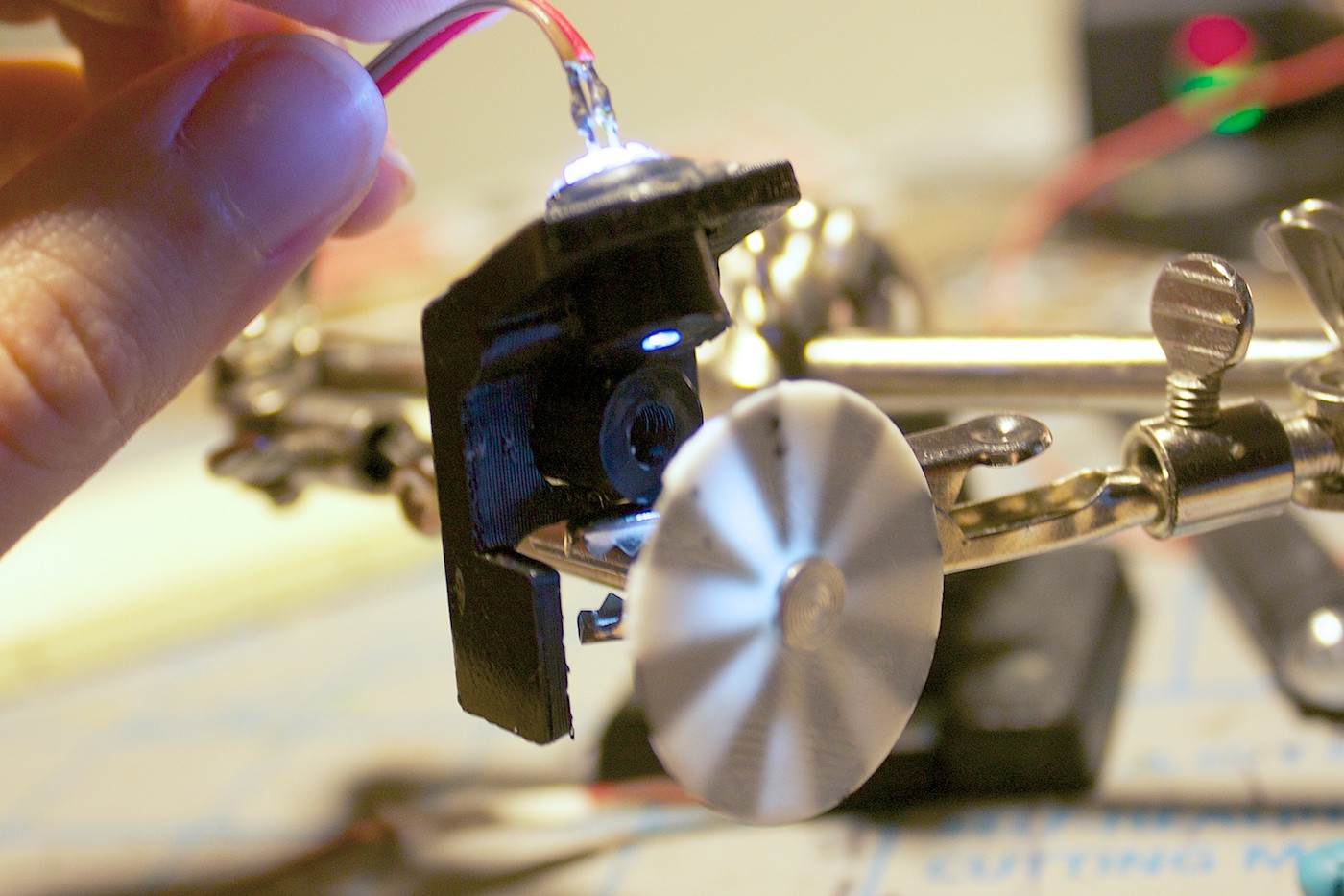
Well, it turned out for the first try we got everything wrong. The tube on the white LED was not needed. The angle of the LED was wrong. The LDR placement was wrong. The mount didn’t attach properly to the bar on the gear set. We went through a lot of iterations…
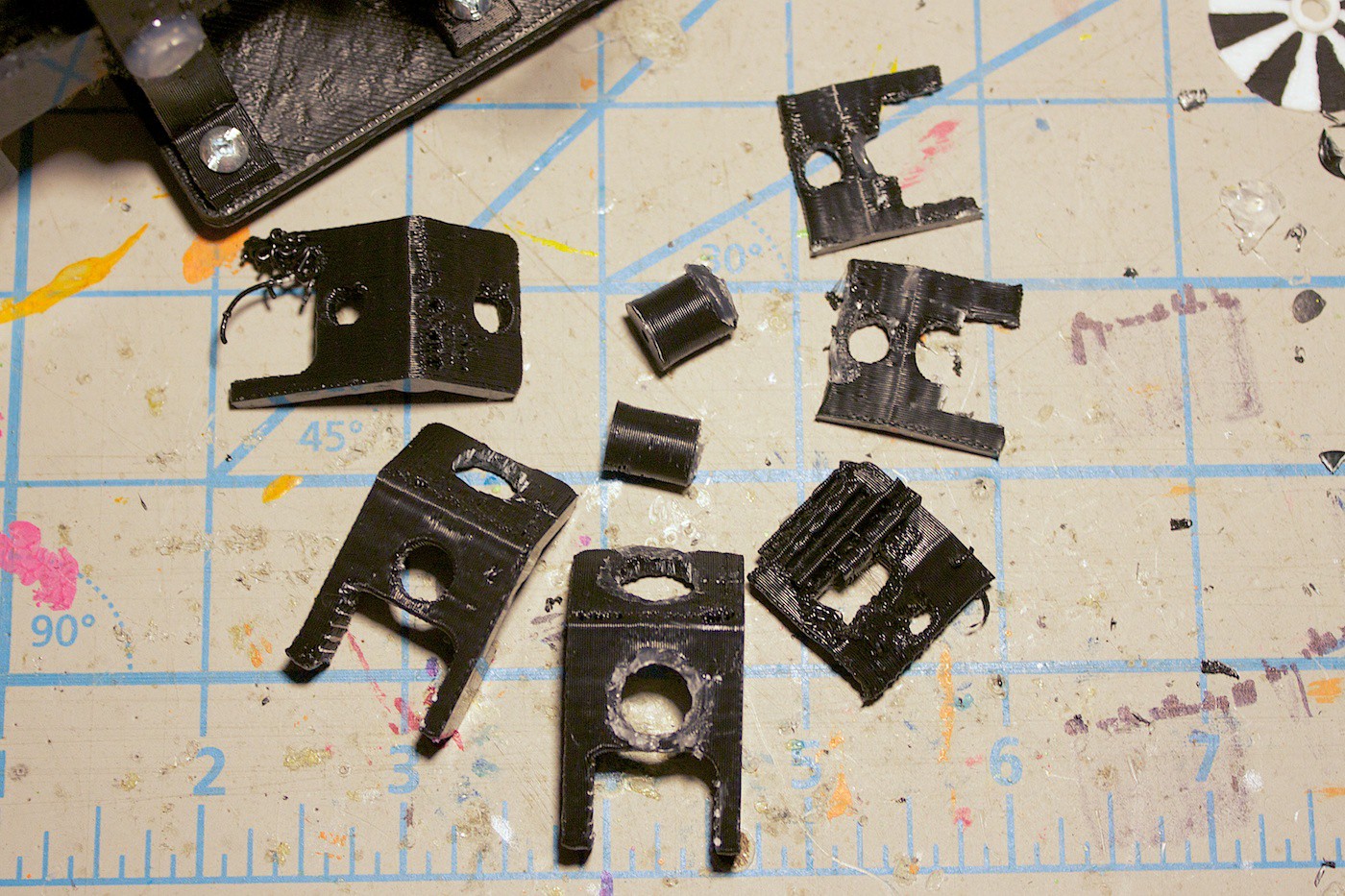
…until finally, we made a version that worked! Woot!

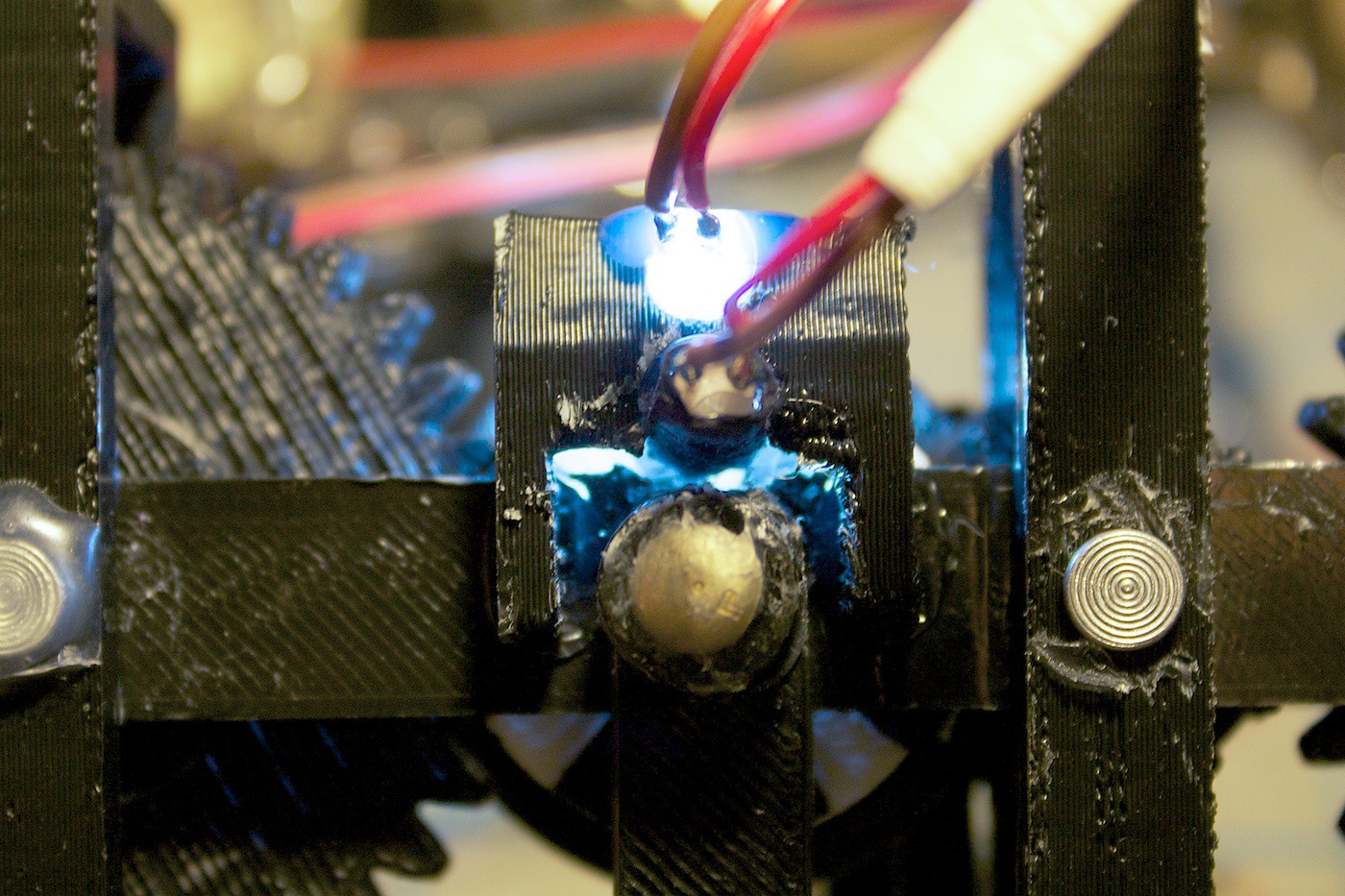
Test in action:
From behind:
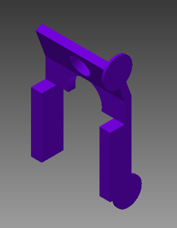
In CAD:
Next up is to create the code to detect when the encoder is changing, and be able to control the motor.
Lessons Learned
When prototyping, sometimes it might be better to try out two ideas at once, rather than just one. I think the design of the encoder LED mount may have been completed faster and with less hassle, if I was designing and iterating on two different ideas concurrently. This never hit us until now :( … Will keep this in mind for next time.
For a complete list of materials to date and the current view of the Z-Axis, please view the Part 3 update.
In the next update we work on the encoder code progress and add buttons!
Discussions
Become a Hackaday.io Member
Create an account to leave a comment. Already have an account? Log In.