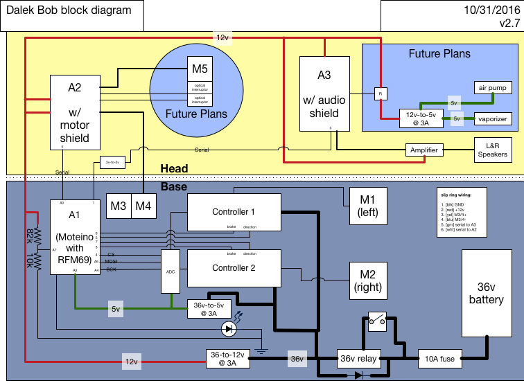
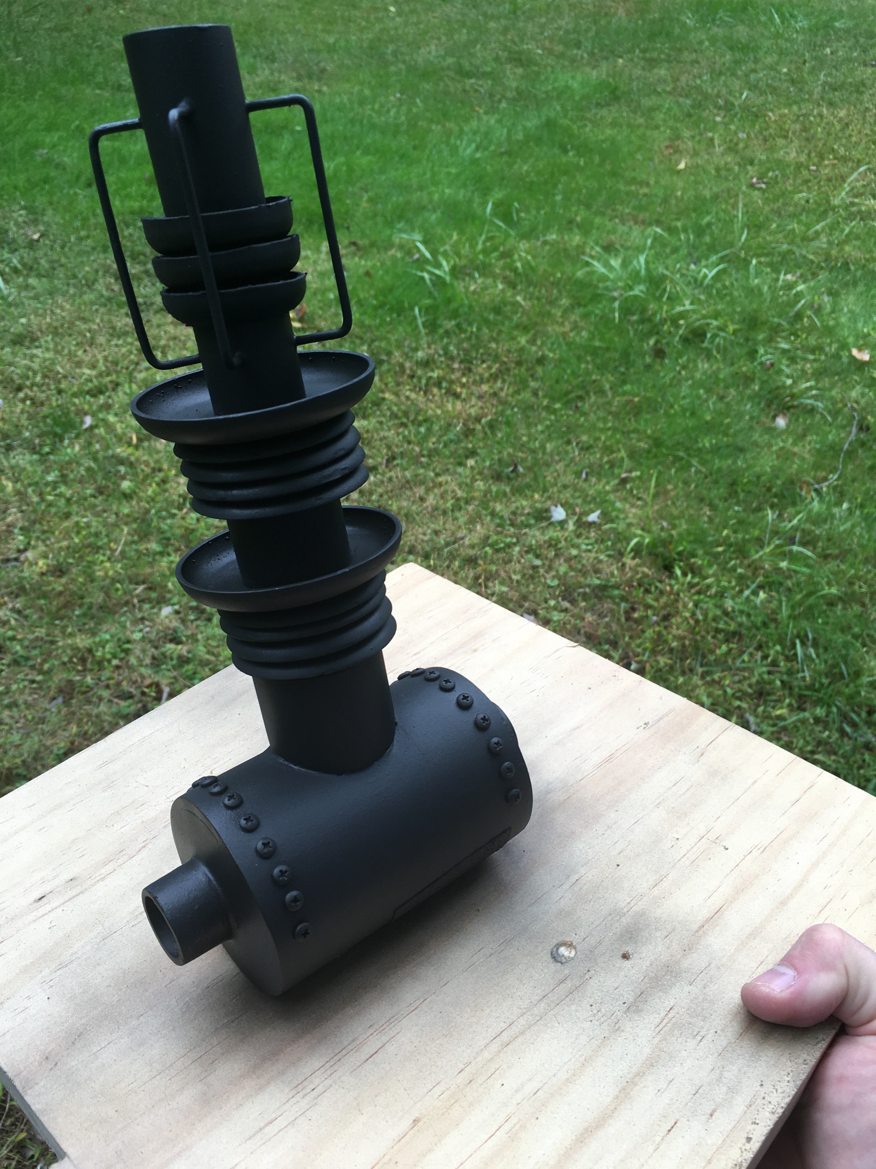
• Phase 15: Fish Or Cut Bait

    Jorj Bauer11/12/2016 at 23:51 0 comments

    So, with this year's deadline approaching... what can I realistically finish? I think the answer is this:

    I'm not going to get to the gun motor or the smoke generator. But everything else! A good set of upgrades. Let's see, how does it all go?

    The 10A fuse, inline, is very compact compared to the circuit breakers. The relay and switch are done, up to the 12v and 5v buck converters. A1, the receiver moteino, is good - now with a voltage divider to monitor the voltage of the battery, and alert when it's getting low (by flashing the light on the power button). The two main motor controllers are stable, and - with a bit of fiddling - are now stable.

    A word about that. The controllers won't switch to reverse easily. I thought they required that the motors be quiescent - sitting near zero - for a while before switching to reverse, or they'd ignore all input. Well, that's not exactly right; it looks more like "when switching in to reverse, you must ramp up (down) from zero to -0.97v, slowly."

    Right. So remember for a moment that the controllers' speed input is analog. At 1v, it starts moving the motors. At 4v, it's running full out. (It appears to be 5v tolerant.) So I'd written the code to ignore the range from [-1v .. 1v] and treat them all as 0v, because they are effectively 0v (the motors aren't moving at all). Which is all fine an good - until you want to go in to reverse. If you don't "ramp up" (down) from 0v to -0.97v over some (yet unknown, but longer-than-instant) period of time, then it hates on you for the next forever-until-you-go-back-to-zero and ignores whatever input you send at it.

    With the controllers being sent voltage through the range from 0 to -1v, it does what I want. I've tuned the code to (more or less) do the right thing. At least it goes in to reverse when I tell it to. Finally. Grudgingly. Might as well be a teenager or something.

    ANYWAY.

    The serial protocol conversion for A2 looks great on paper, but of course has an unintended consequence. The Moteino, like most of the Arduino series, have only one hardware serial port - which means that, to talk with two different serial devices at the same time, we have to do it by Bit Banging. Which takes time. Which means we're not processing RF input. Which comes at regular intervals while driving. Which leads to a truly unexpected consequence: the remote is sending, willy-nilly, commands to play music, engage brakes, move the Dalek, whatever - whenever it gets to that bit of code. And now the receiver is dumping basically every other packet because it takes too long to get through the handling code.

    Okay, a quick RingBuffer to queue what's going out or coming in, and then deal with the sending/receiving processing after - and now the sending happens in one packet, and the receiving processes the bytes after they've been received in a safer way. So I can, for example, swivel the shoulders at the same time that I'm driving forward. Or have it play sounds while moving the shoulder. Or whatever.

    So that's A2 sorted! A3: the teensy is doing a great job. Mostly. The WAV files are a bit loud, compared to the audio input from the wireless mic. A little input level fixing in the mixer code, and we're good there.

    The fog machine, on the other hand... well, I bought three different e-cigarettes and we wind up with nothing. The first worked, but didn't seal well. The next two were identical - the battery has too damn much intelligence. "Give me the stupidest one you have; that's less for me to undo." And even that wasn't dumb enough. It has this silly "five button presses to disable the battery" which is fine, and some "three button presses to set some value or other" which I don't really understand (and doesn't match its documentation), and if that had been all, ti would have been okay.

    It wasn't okay.

    Apparently the embedded battery controllers hate - HATE - to have the batteries actually removed. They go in to some undocumented mode to not allow you do anything until... well, I don't know...

    Read more »

  • Phase 14: Clean Up, Clean Up

    Jorj Bauer10/31/2016 at 17:28 0 comments

    I've been feverishly pulling the pieces back together!

    New fuses arrived - nice 10A fast-blow fuses, which are small and take up no real space due to the inline fuse holder. Together with some better continuous duty 36v relays, I've got a better power system. Which I'd post a picture of right here but apparently I've taken none? Amazing.

    From there, I moved on to the head electronics. The latest revision of the block diagram shows the three microcontrollers that are running this thing. A2 had been in the base with the drive circuitry, while A3 had been in the head with the sound circuitry. I've moved A2 to the head - so that I might eventually use it to also drive a motor for the gun stalk, which will require a couple of limiting sensors. I don't have enough wires in the slip ring (between the head and the base) to accommodate two more sensors, but I realized I could move the whole controller up, and run the motors for the shoulder over two of the lines in the slip ring (two lines that had been planned to run the motor in the head for the gun stalk).

    (Hmm. I see that's not quite up to date, but I'll deal with that later. Close enough, I suppose. You'll have to imagine it shows the things I say it does...)

    A side effect of this is that I had to convert A2 to a serial protocol. It had been using four pins as a parallel bus for controlling shoulder and gun motor direction (not that there's a gun motor attached, but the code is all in place).

    Now, A1 is a 3.3v Moteino while A2 and A3 are 5v Arduino Unos. To get serial communication working properly I had to add a couple of 3.3v-to-5v logic level shifters. No big deal, dropped in and the electronics are back in business.

    At this point I needed to mount things in the head unit: the new 12.5w amplifier and two Arduino Unos. Space is pretty tight in the head, and I still want to add a motor; two limiting sensors; and a fog machine. (Yeah, I'll come back around to that one later, too.)

    I already have four bolts in the head section that are holding the head on to the lazy susan that's between the two halves, so I reused a couple of those bolts with a couple of angle brackets to mount two pieces of MDF to which all the electronics are mounted. Like so (this side is the audio system and amplifier):

    And here you can see from the front (where the gun will be mounted) both of the sides:

    It was about here that I decided it was time to revisit the audio system. The old audio system - an Adafruit Wav shield - plays files off of an SD card on demand. I like that, but wanted to add a live feed through a ring modulator so that we can make Bob talk. And I had a plan to do that last year, which got partly built and has been sitting in a box ... somewhere ... waiting ... ah, found it! Only about 20 minutes of searching.

    So I pulled those all back out and rebuild it on to one board - where A2 is now a Teensy 3.1 with its Audio shield. Same functionality, smaller footprint! Here you see it all hooked up with the speaker (while I was debugging serial communication, apparently):

    Do you even see it? The Teensy is in the upper left corner of the board, with the amplifier in the lower left, and the remaining Arduino Uno for the shoulder motors in the upper right.

    The Teensy is also a 3.3v device so the logic level shifter is now just for the Uno; and there's an audio input jack that's dangling around the left side of the Dalek's head here, just out of sight . That thing dangling is the receiver half of this wireless 2.4 GHz audio microphone - a quick hack to get audio input in to the device. Combined with code to implement the ring modulator, and some small modifications to the serial protocol and remote's code, and we've got a new live voice feed! We spent some time making the Dalek say silly things before buttoning it up.

    Updating the code in the Teensy is no more troublesome than it ever was, but I'm finding it really frustrating now that I've got wireless programming for the base controller and the one in the remote....

    Read more »

  • Phase 13: Lucky Number 13

    Jorj Bauer10/21/2016 at 00:42 0 comments

    Everything seems to be arriving before it was due! What a stroke of good luck. Or, bad timing. I'm not sure which just yet.

    I've replaced the prototype foam core mount with some thin particle board, many angle brackets, and some wood scraps (behind the particle board, in to which the screws are screwed). With it all together, the Dalek slips over top (just barely). There are still details to work out, but this is the rough layout with all of the base components, more or less:

    I say "more or less" because the round metal can is a 36v golf cart continuous duty relay, which I'm hoping to replace with a solid state relay; and the moteino is sitting there by itself, without the I2C Digital-to-Analog converters.

    Now comes the gut-wrenching piece of the build: I have to take all of that apart, bond the base plates, do some woodworking cleanup on them, prime and paint them, replace the motors and their brackets (I found cheap replacements that I want to try out), and begin reassembling everything.

    What, you don't believe that it fits? Okay, fine.

    Just. Barely.

    I'm planning to mount the shoulder motor controller board to the top of the base cavity, so it won't need space to mount to the base enclosure. I do have a little space to play with on the back, where the circuit breaker is; if I trim back the base plate a little I could move the 36-to-5v and 36-to-12v buck regulators (which are currently on the left and right outside edges of the battery compartment, out of sight here, but visible above the left tire in the first shot above).

    Speaking of the tires: one of them began rubbing oddly after I test-fit this. I'm not terribly surprised: the wheel is pivoting a little in its makeshift mount. Right now, the machine screw bolts are holding the clamp plate against the wood:

    You can see from the shadow that the plate is fairly high off of the wood. Those machine screws are going to rip through the wood if I try to clamp them down very tightly. So, it's time to get some proper bolts that will go through the hole in the wood, where I should be able to apply an appropriate amount of pressure to keep the motors mounted straight. I hope.

    Anyway. Things that came in early:

    * The DC/DC solid state relay. Which lasted about 4 hours before it blew itself out. Seriously, I've got terrible experiences with solid state relays. I've ordered two more appropriate 36v continuous duty relays; I really don't want to use the golf cart relay. It runs really hot.

    * Another pair of motors and brackets. Unfortunately they're a *smidge* wider than the current tires, and don't fit in the base. I was hoping to put them in and reassemble the hoverboard, but I guess that's not happening.

    * MCP 4922 dual 12-bit Digital-to-Analog converters.

    So I cleaned up the woodwork on the base and spraypainted it black:

    Mounted the motors with some proper bolts:

    Remounted the support structure and wired up the whole lot, removing most of the worthless wires on the controllers (here, with the solid state relay, just before connecting the motors):

    And spent some time flirting with disaster! One driving test, the base went completely out of control: the SDI line to the DAC came loose, and the DAC decided that meant I wanted "full ramming speed" - running it in to my stairs. Fortunately, not much damage; just a smudge of black on a baseboard and a spot on the base where it has lost its black paint. (You can see it in the indoor video below; a black spot on the outlet cover and a line heading toward the stairs. Whoops yet again.)

    The second failure was more spectacular. The same basic problem happened - the SDI line came loose - but more interestingly, it happened while turning. So one wheel wound up at full speed while the other was full stop. The base did doughnuts in my dining room for a short while, eventually throwing the battery across the room. Again, fortunately, no real damage; just a few skid marks on my floor ("oh, just doing doughnuts with the Dalek, no biggie").

    But eventually I figured out...

    Read more »

  • Phase 12: the Wait is Over

    Jorj Bauer10/20/2016 at 16:53 0 comments

    That was the shortest Long Wait *ever*.

    Enough of the hyperbolic statements about delays! The controllers arrived a day early, so last night was filled with interactions like this.

    The slight scraping noise is one of the wheels brushing against the cardboard box; nothing I'm worried about. Crappy rushed woodworking aside, I'm pretty happy with this. (And damn, that bad cut is going to bug me until I fix it. I've slated that for mid-week next week for reasons of logistics but I'm not sure I can stand waiting that long...)

    That was controlled by the new remote, running through the Moteino (on the protoboard) which is running both motors from one Analog-to-Digital converter (the only one I have at the moment). The rightmost flashing light is debugging code that's toggling the onboard LED whenever it gets a "G" pulse (telling the motors to run for a short while), and the other flashing LED is on an RS232 USB adapter (the board's sending serial output for debugging while I tuned the ADC).

    There are a few really ... interesting ... behaviors of the new controllers.

    There's a reverse line that, when pulled to ground, tells the controller to run the motor backwards. So I set up the Moteino with a pin to do so, and it works. It looks like, when running backward, the controller will only run at about 2/3 speed.

    Now, that's got to be a safety feature. I wish I could disable it. And I may very well open up one of the controllers to try, if I have extra time on the project. If it's anything like the last (cheap, eBay, low-quality) controller I disasembled, I'm going to find that it's all embedded firmware controlling this with no way to disable this behavior. I can live with it, though; I thought about making it run slower when going backward anyway. It just slightly screws up my vector calculations when turning - but I can probably measure the difference and compensate if I need to.

    This controller has three "speeds" you can set - high, medium, and low. So I put it in to "medium" mode, and found that when you start rolling the wheel in "medium" mode, it actually turns backward a bit before going forward. Not really nice. I couldn't find any way around this (slower ramp-up, faster ramp-up, jumping right to a higher throttle value). So I won't be using that feature; easy enough to avoid and just implement myself. In fact, it's already implemented - the first two spins of the wheels in the video are forward and backward in "slow" mode before I throw it in to "fast" mode and spin forward a few times at full throttle, then coming down to about half for a second, before finally stopping.

    Both of those I can deal with. But the third is trickier.

    The reason I don't throw the controller in to reverse while in high speed is that, well, I can't. If the motors are spinning more than (some speed), they won't reverse until they're spinning less than (some perhaps-different speed).

    I can see how that would be important. Back EMF, damage to the motors, safety. Yeah yeah. BUT. If it's in the "too fast" state and you try to hit reverse, it doesn't *just* ignore you until the motor is slow enough. It *continues* to ignore you until you stop telling it to move at all.

    So the Moteino is going to have to keep an estimate of how fast the motor is going, forward or backward, in order to figure out what's actually happening so that it can reverse.

    Fortunately this probably won't be a problem in the real world. The load of actually moving Bob's actual mass should stop the motors pretty quickly and allow for quick reversing. Regardless, I find myself writing code to estimate the current motor speed and to fall off with an estimate of the decay. I forsee lots of testing that will be close to correct, but which I'll want to tune forever. :/

    Anyway - now that the controllers are here, I can finally estimate how to mount everything. Here's a mock-up in foam core:

    The line drawn on the base is the clearance inside the model. WIth so little space, I can't really mount anything there,...

    Read more »

  • Phase 11: the Long, Long Wait

    Jorj Bauer10/19/2016 at 12:18 0 comments

    Ugh - I'm waiting for parts. Today the battery charger should arrive, and tomorrow I'm expecting the new controllers. I've done just about all I can with rebuilding the base plate until the parts arrive, so I can figure out how to lay out the interior around those sizes. Sigh.

    So, I've redrawn the block diagram:

    ... which shows off that I have no idea how I'm going to connect the gun motor. The idea was to get a low-speed right angle motor (check: 2 rpm!), connect it to one side of the gun barrel, and then I'd have an up/down control for aiming the gun stalk. Unfortunately, I'd also have a way to break through the gun box itself - when kids wound up driving the Dalek and started trying to rotate the gun up beyond its limits. So I need a limiter of some sort.

    The easy answer is to use a couple of optical sensors; as long as the sensor is blocked, the gun stalk is free to rotate. One would break for upward rotation and another for downward, so the Dalek could still figure out which way to move. But to do that (where the sensors are directly connected to the Arduino that's driving the motor), I need two more signal lines down to the base - and I only have one free line in the slip ring.

    I think what I'll need to do is revisit the way the audio shield works. Right now A1 has its serial TX line going to the RX of A3 - unidirectional communication. If I use the remaining slip ring line for the reverse path, then A3 can transmit back to A2. (Another unidirectional line, which violates my sense of "rightness", but it's better than dragging the signal to A1 and then resending to A2.) I'll have to write the protocol such that a steady stream of "ok" is being sent from A3 - or I'd be in danger of failing open, where A3 isn't working correctly, and A2 drives the gun stalk through the gun box. And I don't particularly like that model, because it would be constantly transmitting - where I'd rather it shut down to save power.

    Another option would be to move the A1-to-A3 serial TX line -- making it A2-to-A3, bidirectionally; with an improvement of the A1-to-A2 communication, removing the four parallel "move this motor now" digital lines and converting to all serial; and relaying music commands through A2. Not the end of the world, I guess; music can fail and not be catastrophic, while the motors are likely to cause a catastrophe if they fail. And it would simplify the interior wiring a bit - replacing 4 parallel lines with 1 serial, and using the remaining already-dangling-free slip ring line.

    Ah well, something to keep rolling around in the back of my mind.

    Since I'm in downtime, I also finally got around to pushing the source code to Github! If you're interested, head over to https://github.com/JorjBauer/swd40 ...

  • Phase 10: Clearance, Clarence

    Jorj Bauer10/18/2016 at 02:23 0 comments

    With the motors mounted up on the base plate, and some quick measurements done, it was clear that the wheels wouldn't quite fit inside the model. As the walls slope up, and the ping pong balls encroach on the interior, they fouled the path of the wheels. Not enough clearance.

    Well, I'm not ready to give up on this plan just yet. I figured all I needed was about three quarters of an inch. Which just so happens to be the thickness of the plywood I'm using for the base of this build. So, a quick trip down to the basement^H^H^H^H^H^H^H^H woodshop: remove the motors and casters again, trim down the base I've got so it's slightly smaller than the current base of the model (matching the original lower base plate, which obscured the motors); grab some spare plywood and trace out another of the same dimensions (more or less; done by trace-and-eye); cut a larger rectangular hole in the middle of the new plate; and blammo, we've got a quick shim layer. Close enough for the moment. If this works out, I'll have some finishing woodwork to do though. (If I only had a radial arm saw. Or room to put one in my house. Sigh.)

    As i'm re-mounting the wheels, here you can see the channel down the center of where the wheels mount to the base.

    And here it is, assembled.

    I also cut out a prototype foam core box to enclose the wheels - the beginning of the structure to hold the circuit boards, controllers, power circuitry, and battery. I'd actually done this before the shim layer, and this is how I knew there wasn't enough clearance: I couldn't fit the box inside the model. So now with the base being a little taller, I cut 3/4" off of the box...

    ... test fit it over the wheels ...

    ... and the box *still* doesn't fit inside the model. Too wide near the front; there's just not enough room between the wheels and the inside sides of the Dalek (where it narrows). I'll worry about that later! For now, let's take the box off and see if the wheels fit as planned...

    Presto! Nice. Looks like I've finally got a way to attach the wheels to the model. Looks like I also could have gotten away with less than 3/4" - maybe 1/2" on this side. I'm not gonna fight that, though.

    Now, I still have to take that apart again and clean up the woodworking so the two have a clean, consistent outer edge; sand the heck out of it (the actual base has several layers of bondo to smooth them out, and I'm not planning on doing that with these layers); prime; and paint gold. It won't be perfect. The wheels and casters are tall enough that you can see each of the casters in the front and back, which I don't want. Maybe if I add another layer of trim on the bottom... well, that's a problem for another night.

  • Phase 9: Mount The Motors!

    Jorj Bauer10/17/2016 at 17:38 0 comments

    So what can I do while I'm waiting for parts? All the mechanical bits, of course.

    If you recall, the original motors were mounted outside-in on the bottom plate.

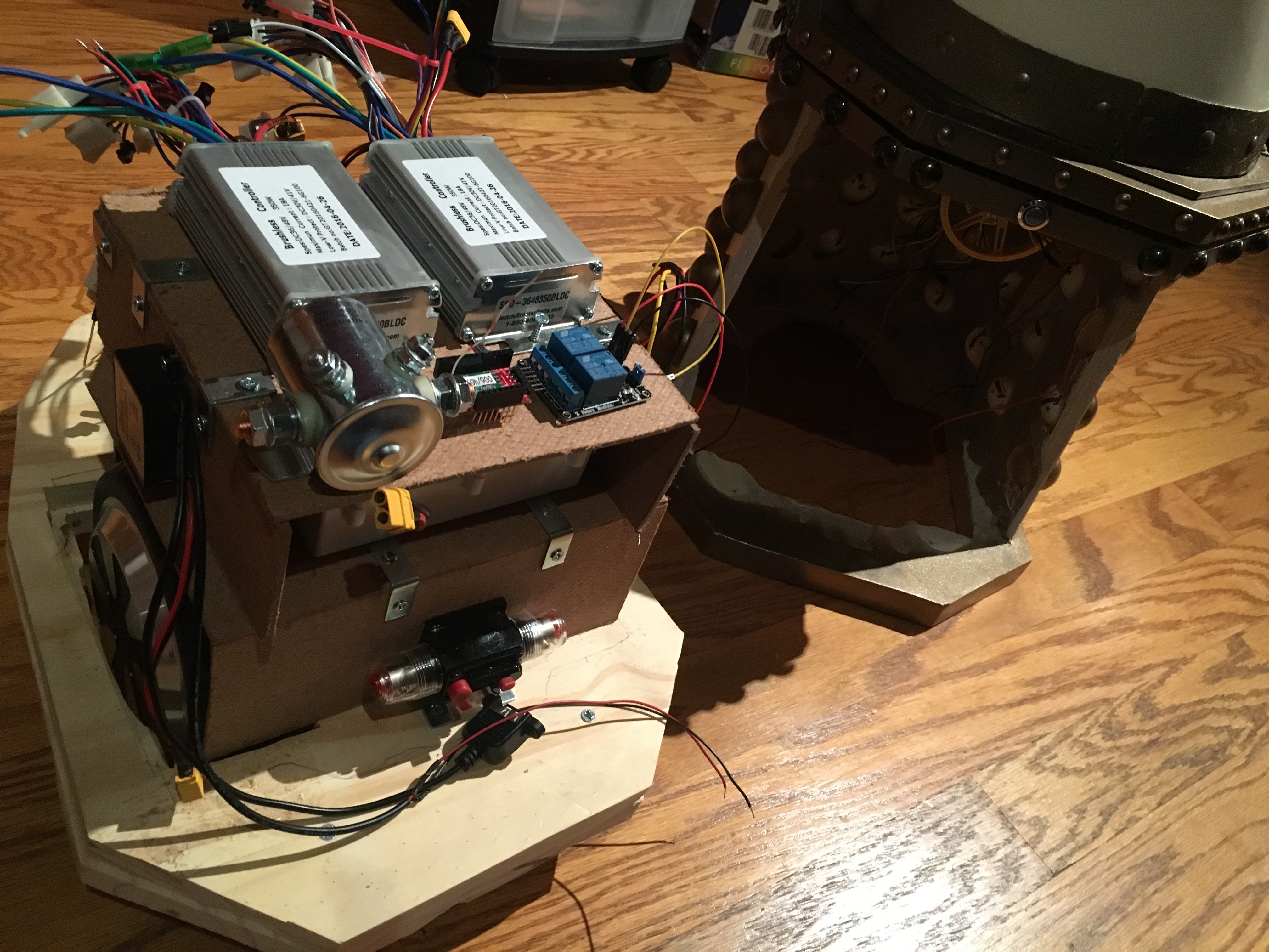
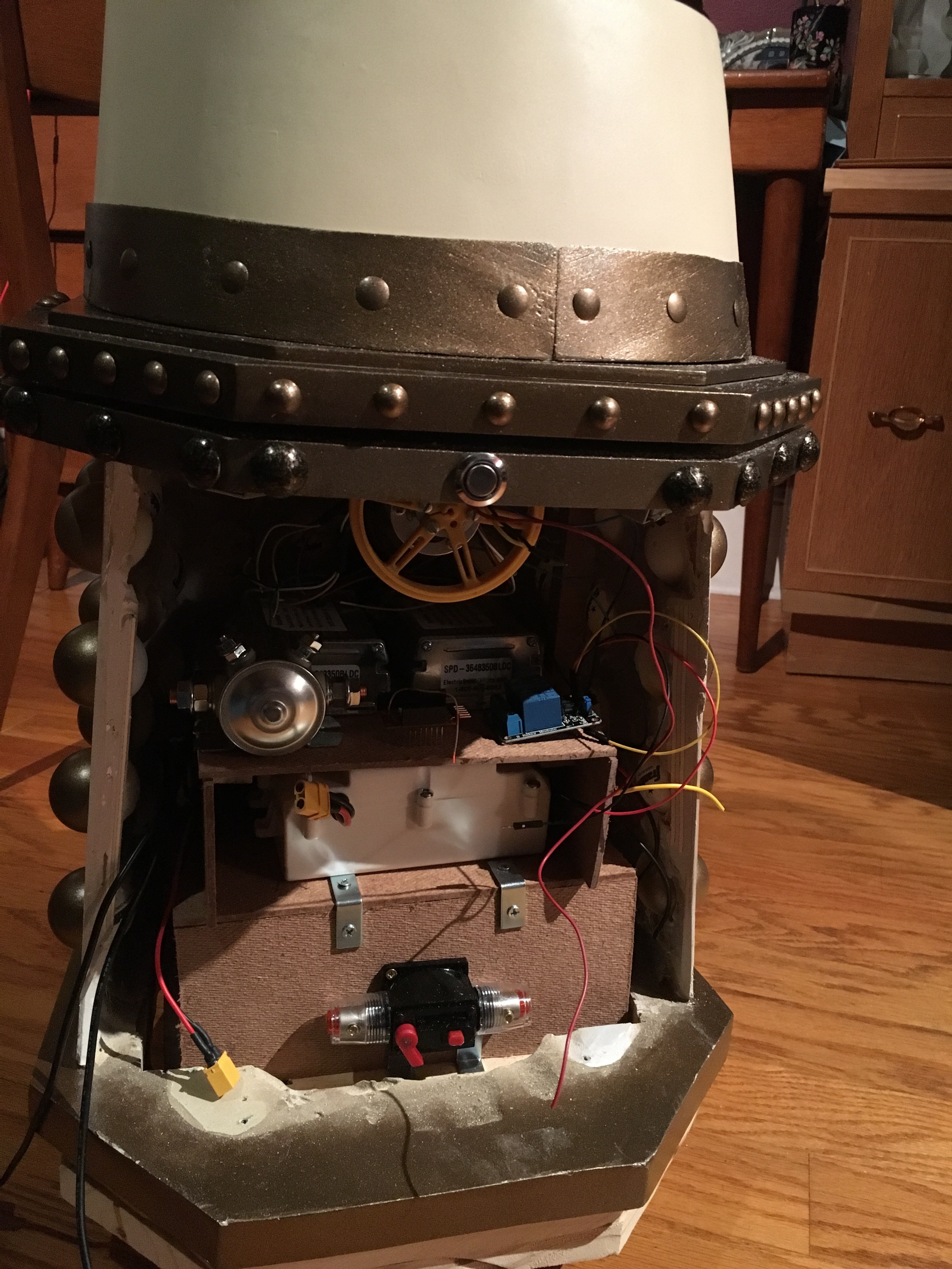
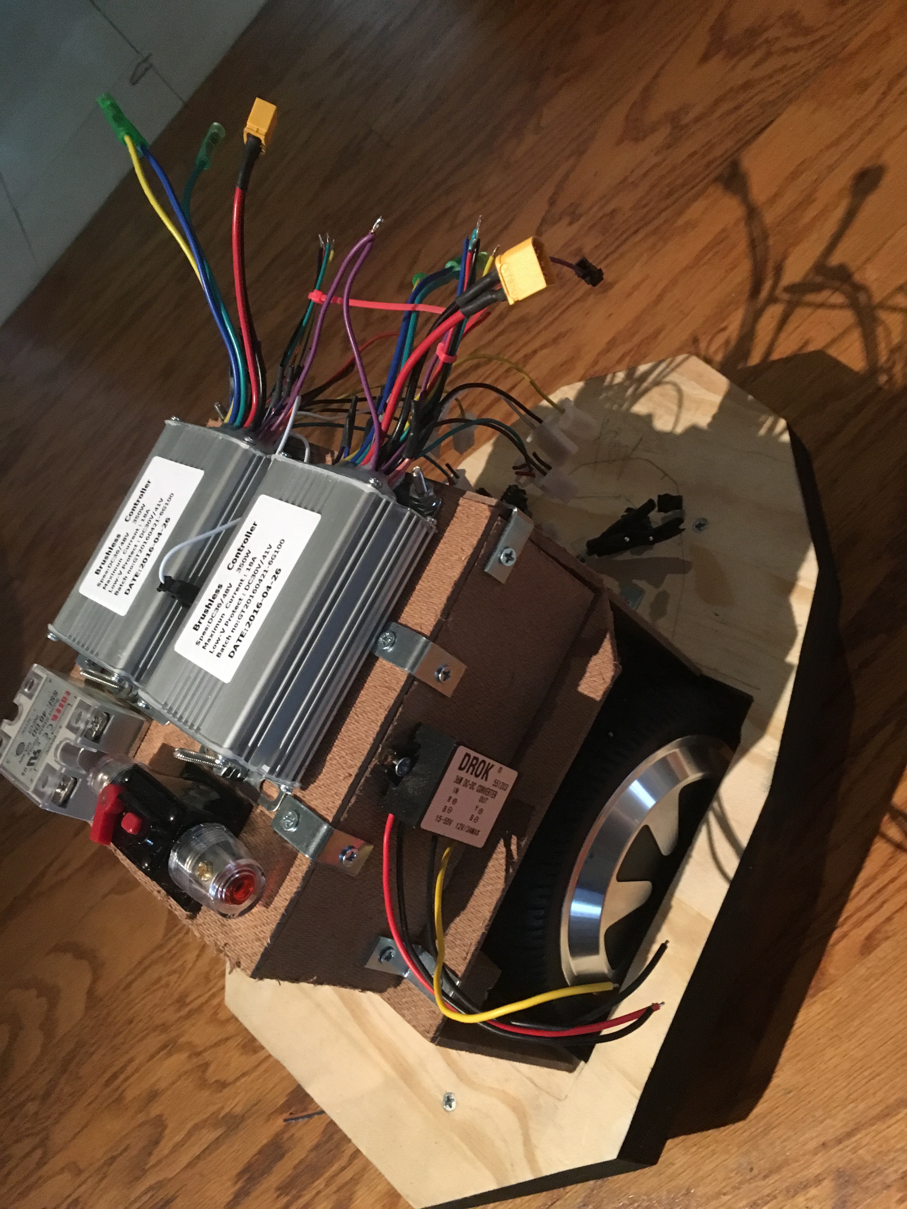
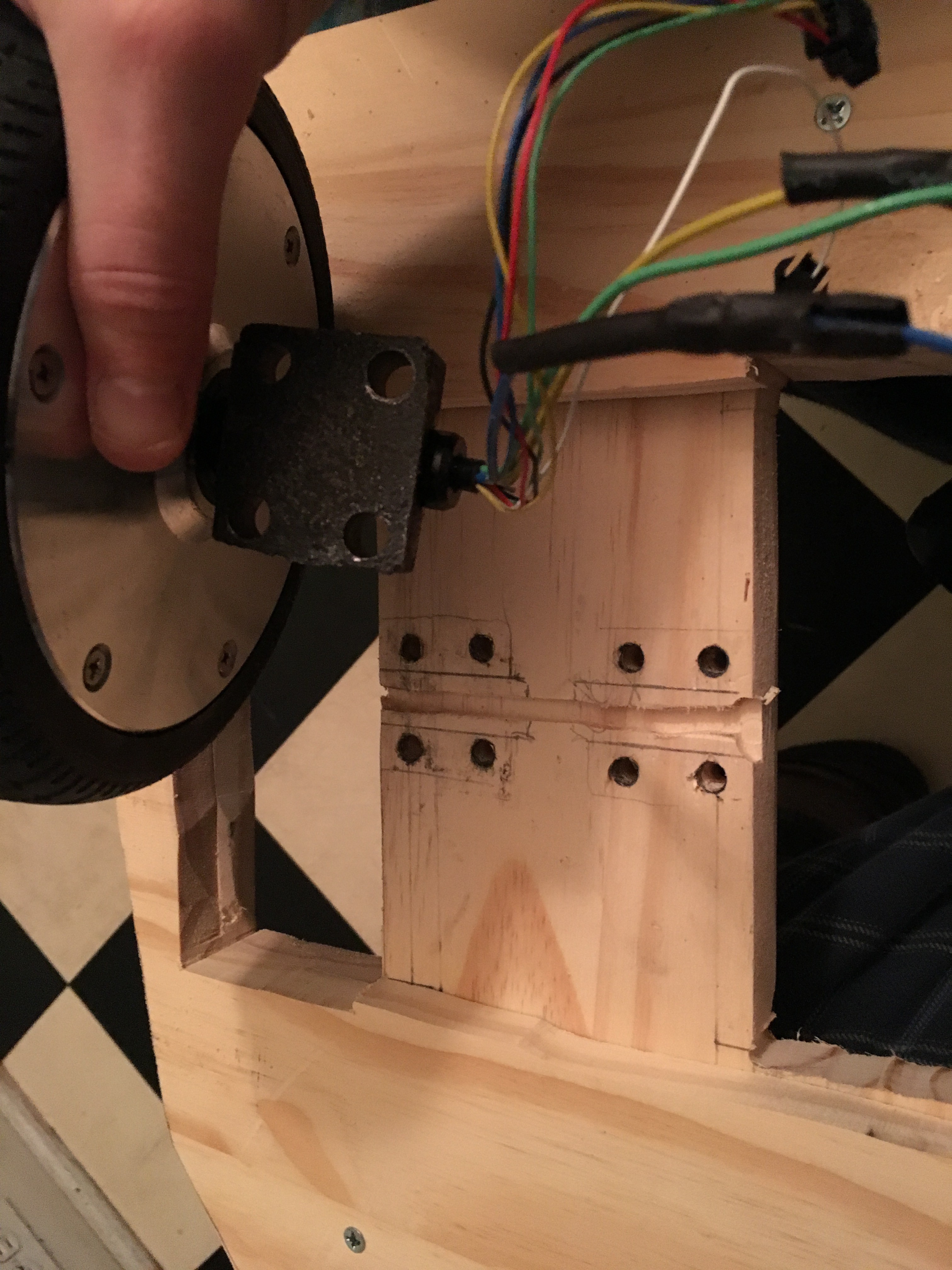
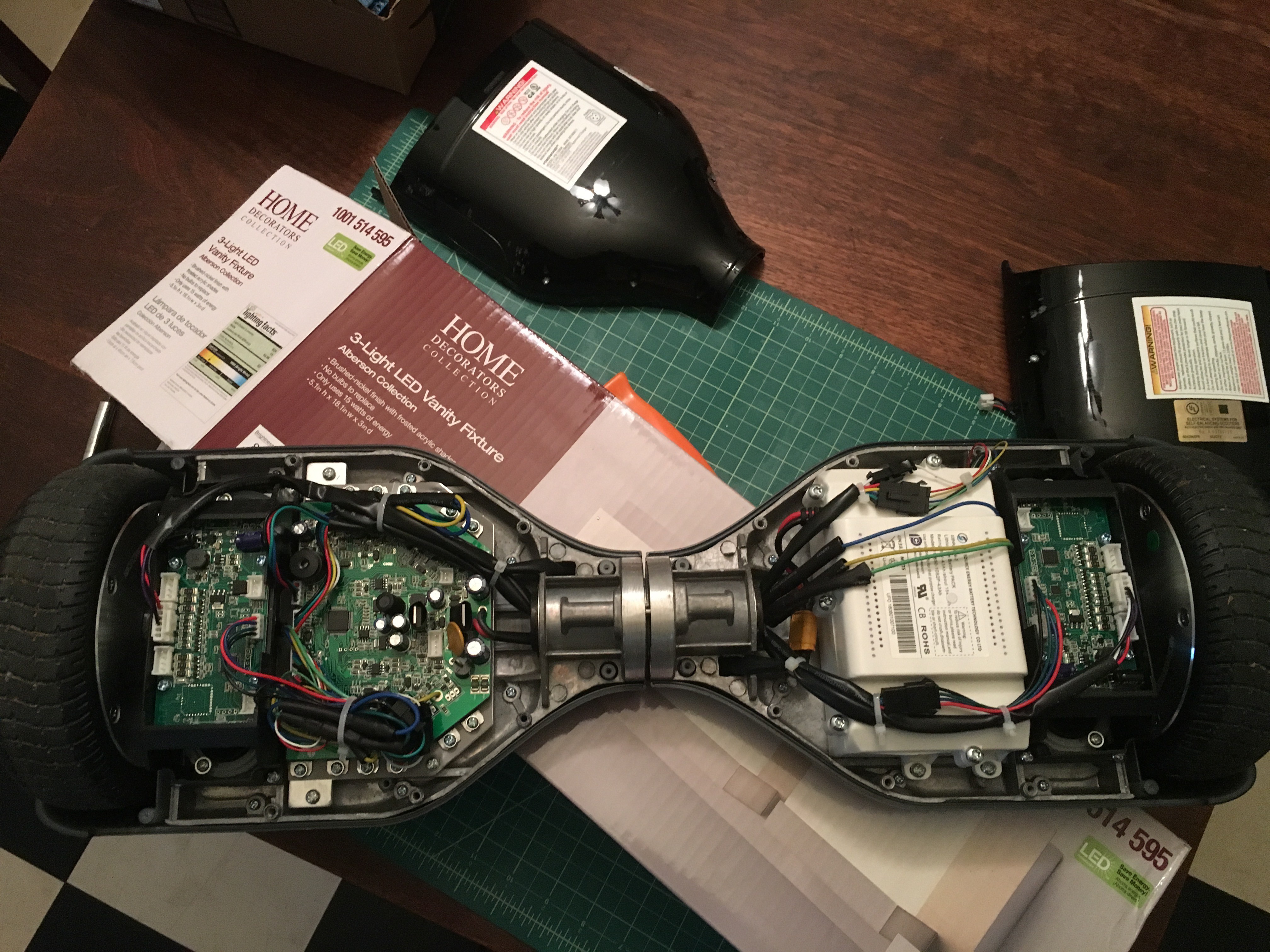
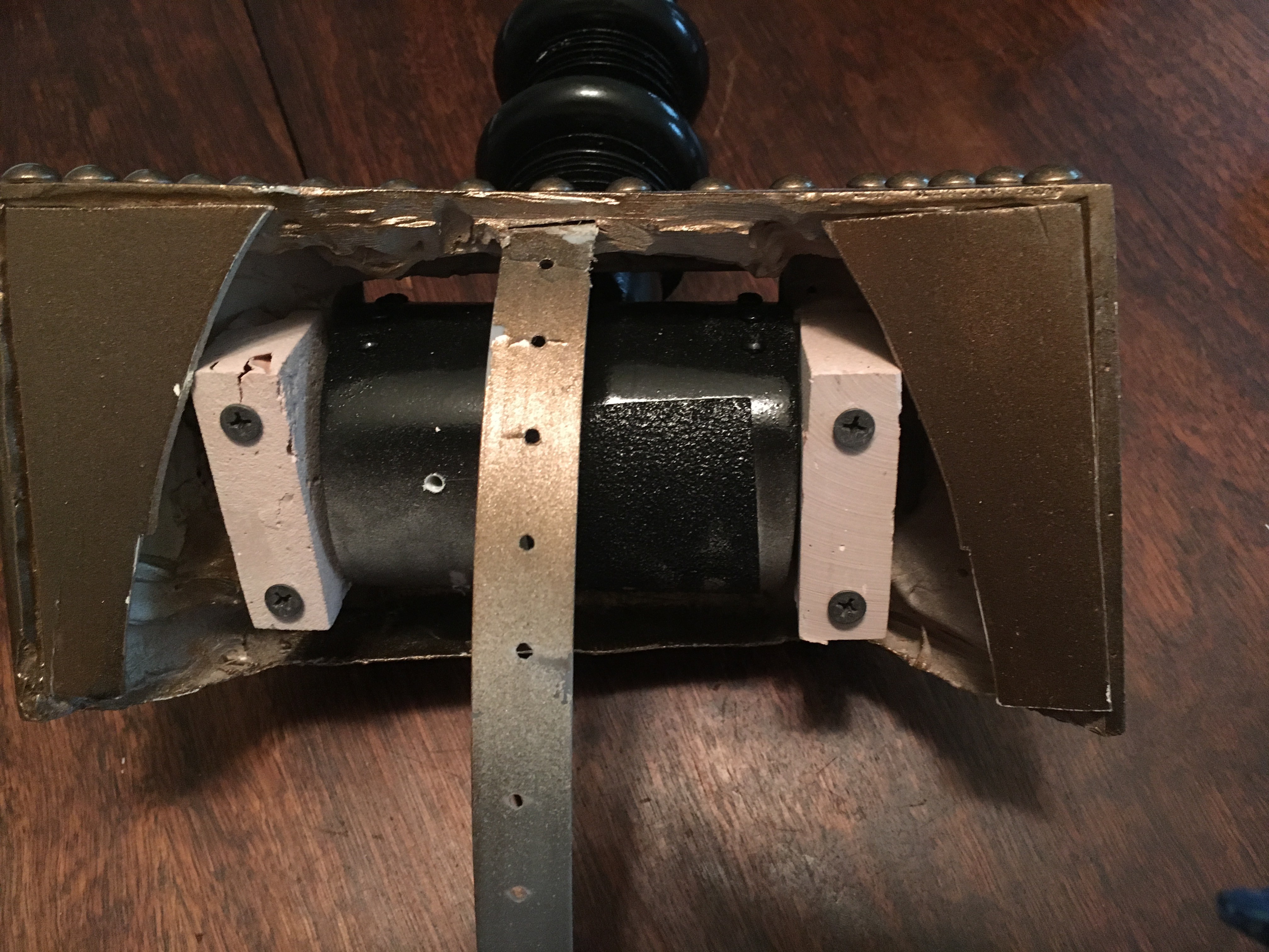
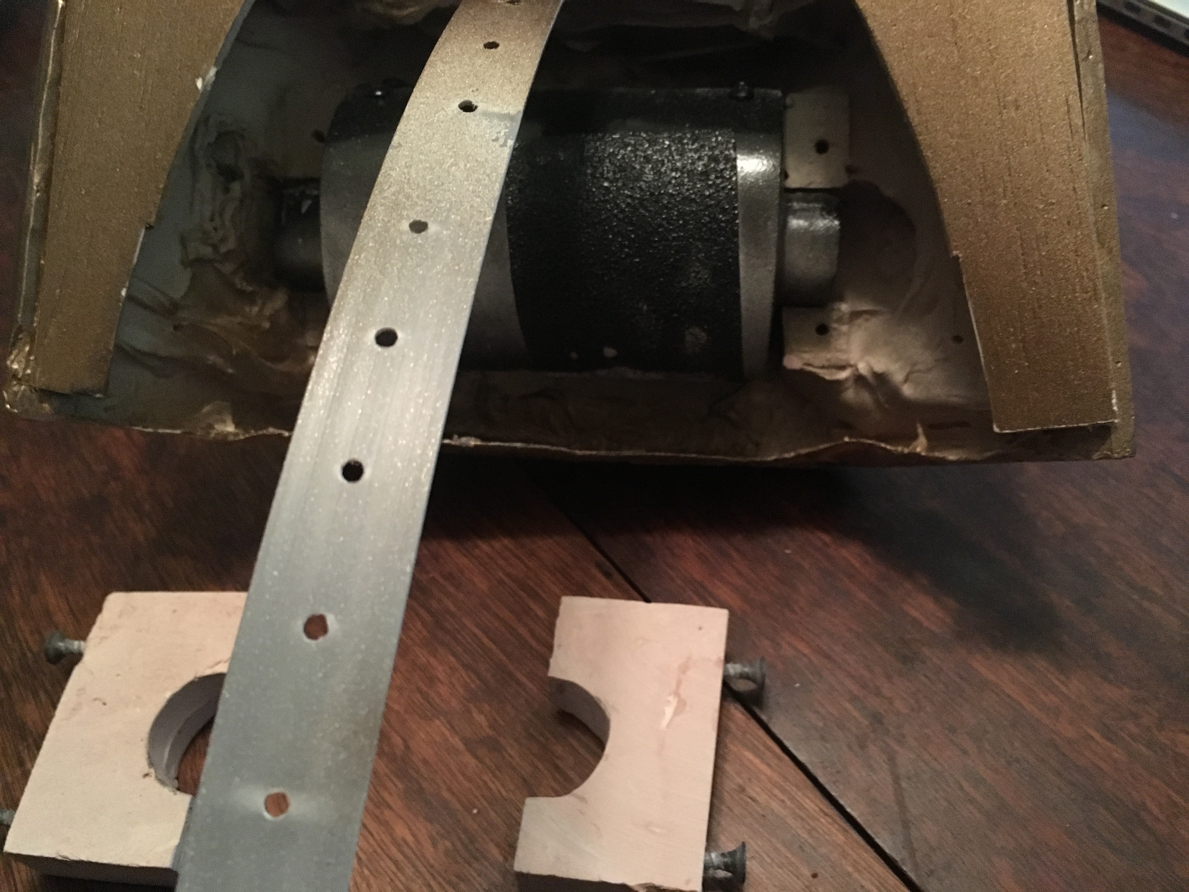
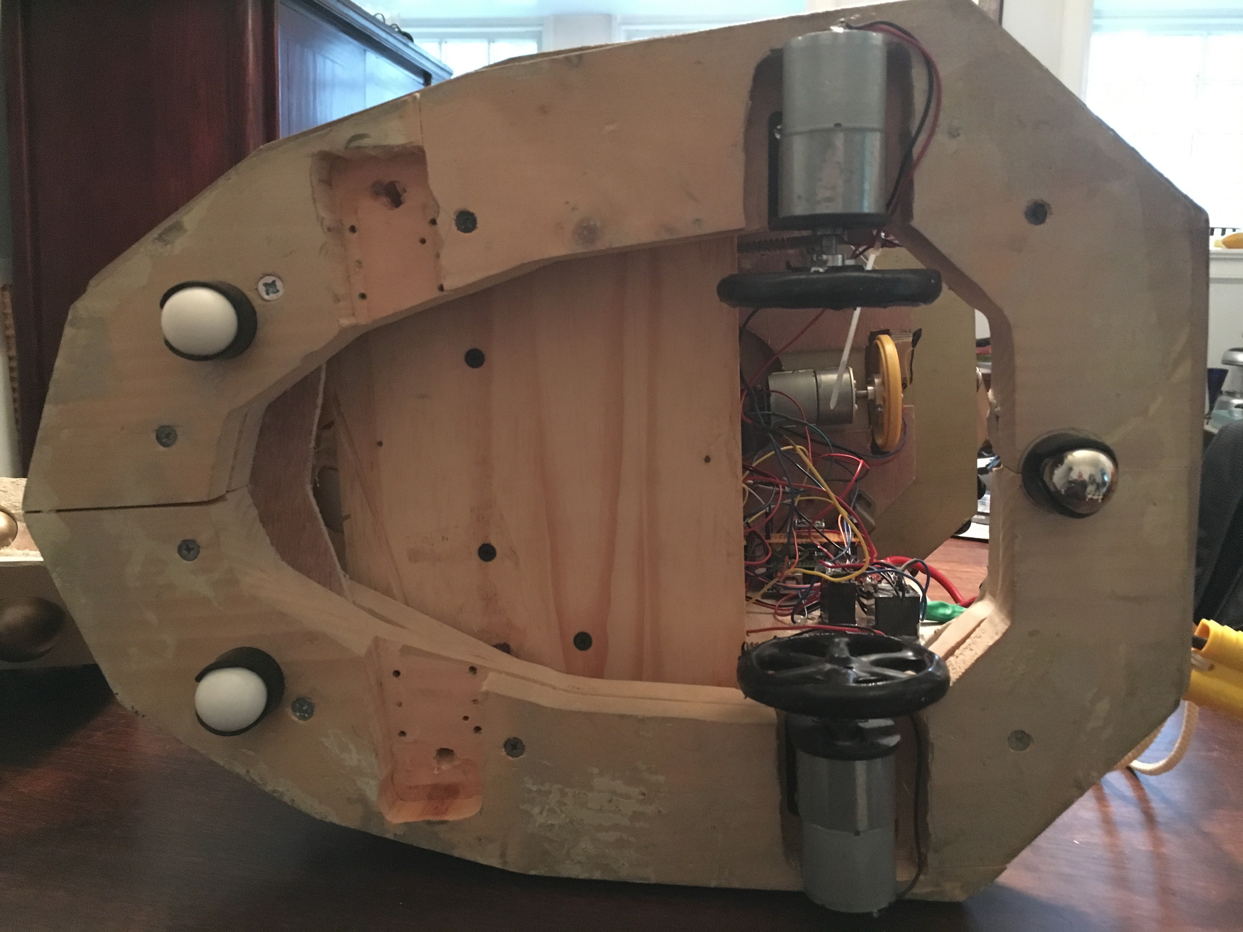
    I mounted them that way because the wheels weren't deep enough to pass through the base, so I basically had to. Well, the new motors are HUGE by comparison, and I'm not entirely sure where they'll fit. So obviously the right answer is to guess, cut a bunch of bits off of the Dalek base, realize you need more clearance through the upper base plate too, take off the lower base plate, cut off more of the upper base plate, and then...

    ... no, that WAS NOT the right answer. About here, I realize there isn't enough mounting space left for the motors. They're just too big. Cue angry yelling, followed by a good long break-and-think.

    Given that I don't want to cut any more of that base until I know what the hell I'm cutting, it's time to cut a new base plate. And given the size of these wheels, I can mount them in-to-out, passed through a sheet of plywood. Which might look like this?

    Cut out the wheel holes, and try a quick fit:

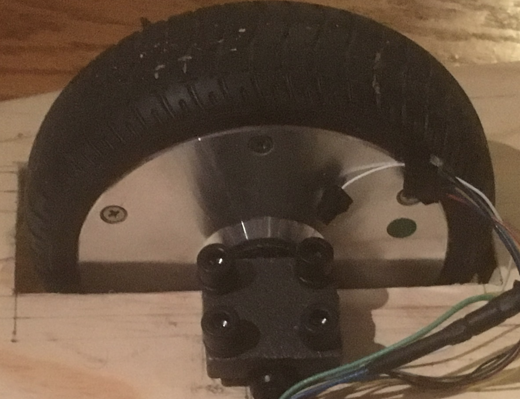
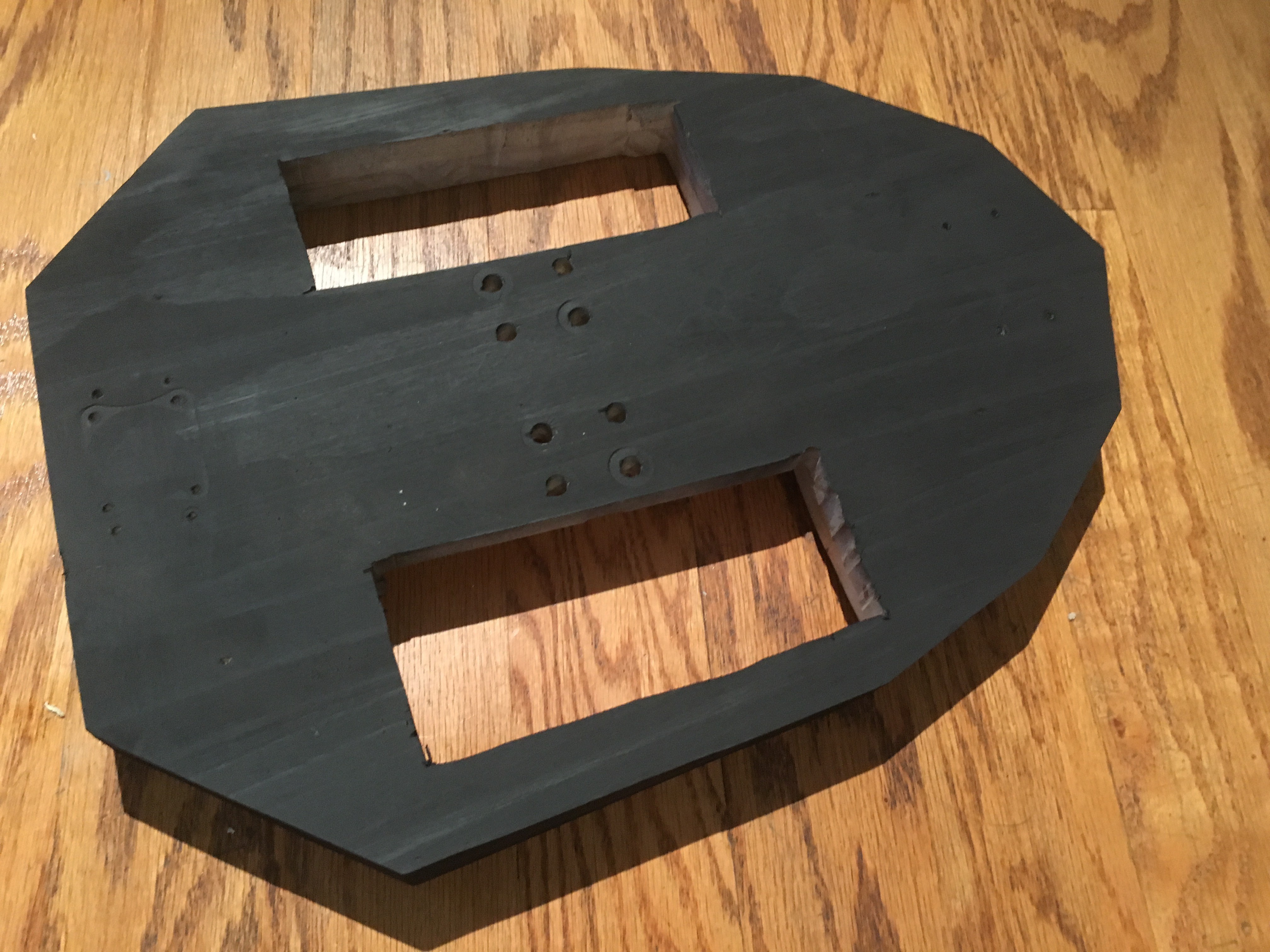
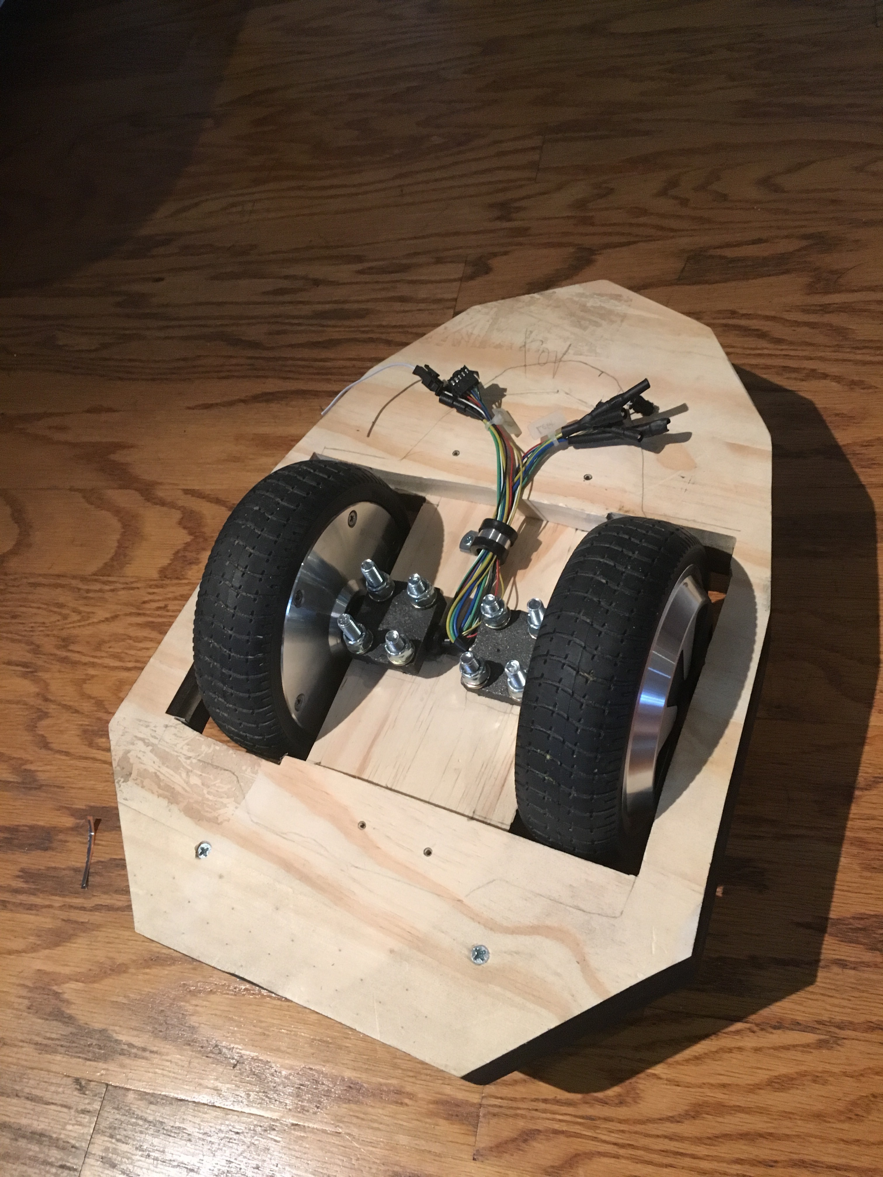
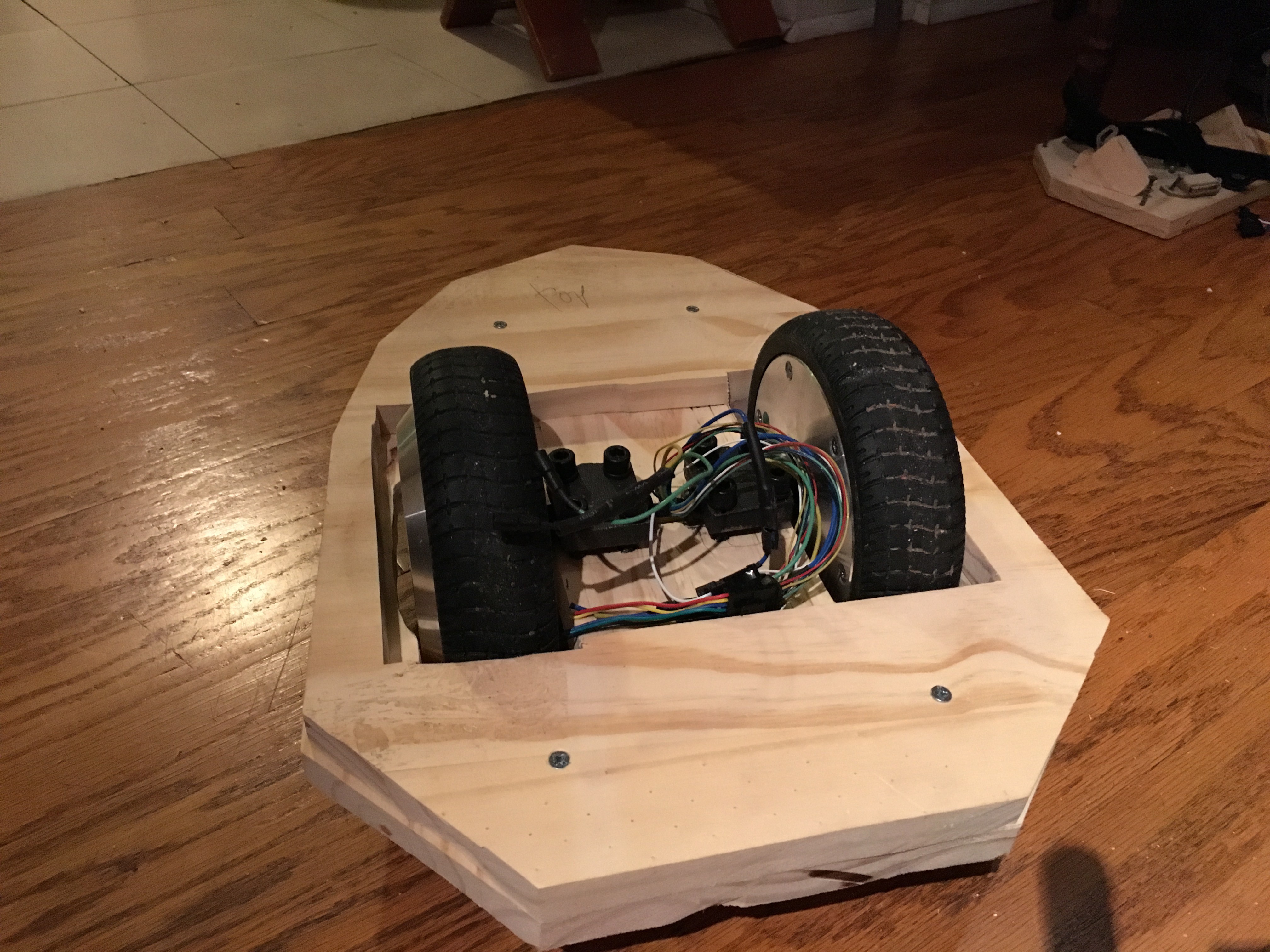
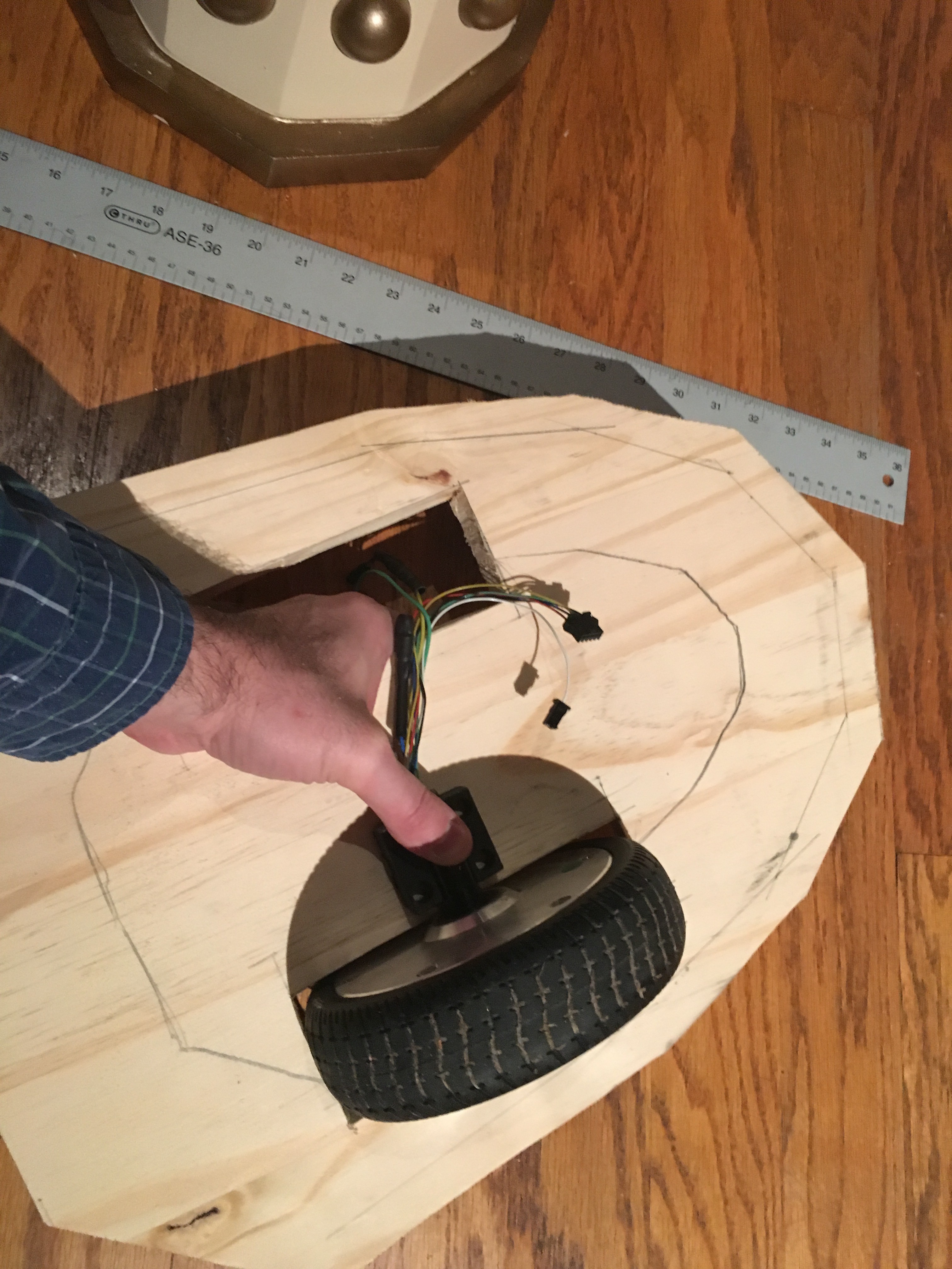
    Looks like it might just work! After marking out where the wheel posts sit, and using my router to cut a 1/4" deep notch right down the center (okay, *mostly* down the center, since I eyeballed it) - drilling pilot holes for the bolts at one size smaller than the bolts, and ... it should hold together well enough until I get some bolts and nuts to better connect them. Does it?
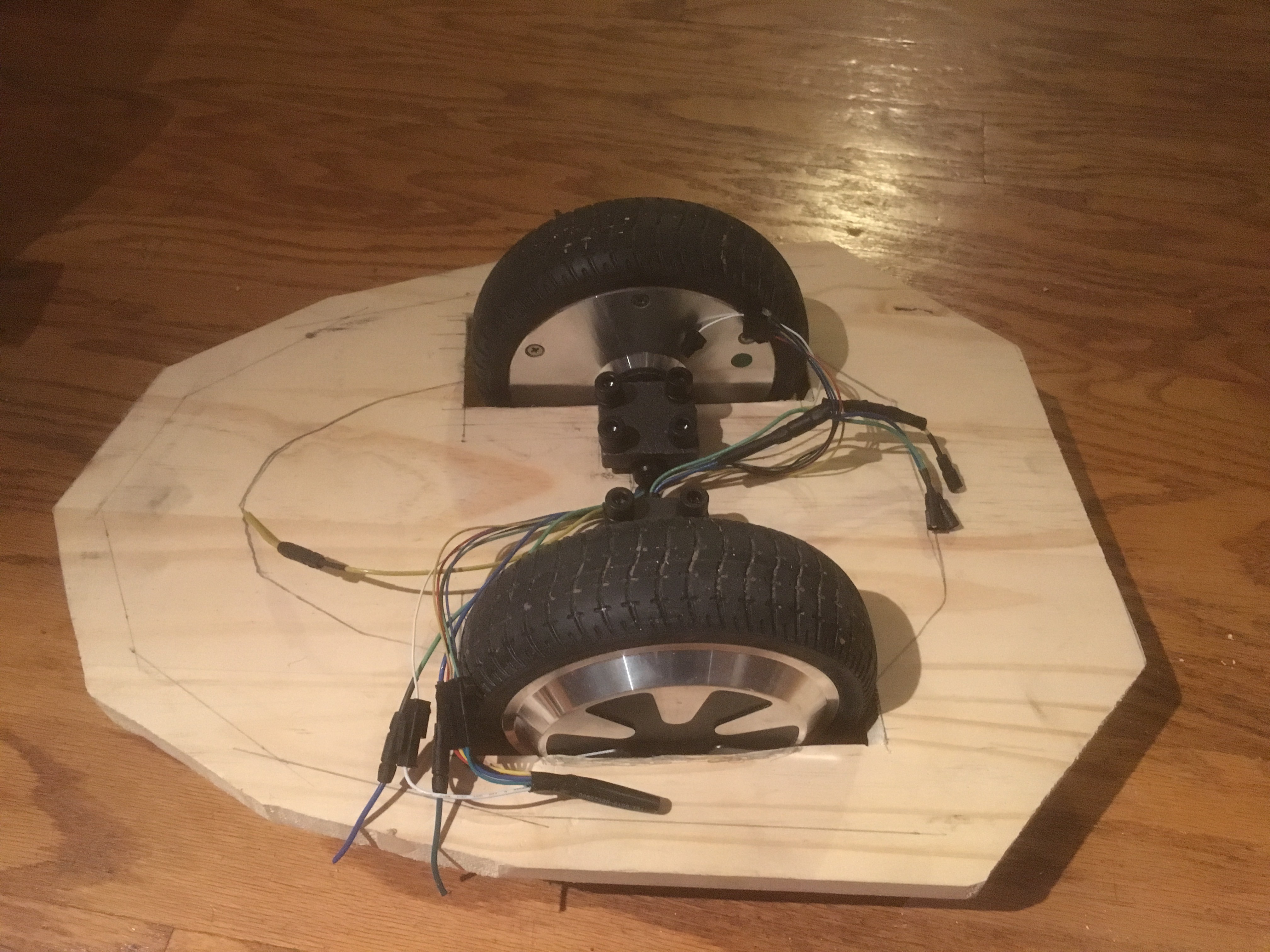
    Yes! And OMG HOW CUTE. It's like proto-mini-Dalek-car. Which got me thinking - if this works, then I will be setting the Bob model on top of it. So if I plan it right, I should be able to mount all of the drive (and power) electronics on this motor base plate, with separable connectors to the shoulder motor board and audio board. At which point this will be a totally separable remote controlled baseplate with no Dalek. That sounds great for debugging and demonstration purposes...

  • Phase 8: Blow More Things Up (oops)

    Jorj Bauer10/17/2016 at 17:18 0 comments

    All in all, I did make progress over the weekend! I also destroyed a few things along the way.

    Starting from where I left off in Phase 7: thinking about controlling the Hoverboard controller directly, I want a 3.3v logic level serial interface, so I was thinking about the Moteino. That would move me to an RFM69 instead of the RFM12b I'd used for wireless before (which I destroyed in Phase 7 by passing +36v in to one of its pins!). Which would mean the transmitter also needs to be converted. It also means I'd be able to reprogram both the remote and the Dalek-side Moteino over RF, instead of having to open them up. Okay, I'm sold.

    Let's start by opening up the old remote. I've lost most of the screws from opening and closing it so many times. There's a lot of hot melt glue holding it all together.

    In the left half is an Arduino Pro Mini 3.3v. Most of the wires coming off of it go to the RFM12B, glued down near the center. A few go to the I2C lines. Two run to the right half, where all of the power circuitry sits - a 110mAh LiPo battery with a SparkFun PowerCell for charging it. There's also a sliding power switch hiding near the left hand grip.

    I bought another cheap knock-off controller for the rebuild. Here it is with the parts all waiting for assembly:

    Cutting off the connector, wiring the Moteino in to the I2C lines:

    Damn, that's so much simpler. Add the two power lines to the other half, put in the power circuitry, add an LED and close it up. Sweet.

    The power switch is now recessed. It's harder to activate, but it's not in your way when you hold the controller. It does foul the down path of the left joystick a little, but that's acceptable for the moment. There's no longer an exposed antenna wire to be broken off, and the wireless programming is really a boon.

    So let's move to the main controller board from the Hoverboard!

    First off: there's a momentary push button (the lower-right red and black connector) that turns the board on and off. I'm going to need to control that from the Moteino inside the Dalek, so I wired that up to a relay.

    Second: I need to communicate to this as if I'm one of the tilt-sensor boards. The Cortex M3 on this board runs some magical program that reads what the two tilt-sensor boards spit out, and drives the motors appropriately.

    I started with [Drew Dibble]'s work, programming the Moteino to send frames like he did. Nothing happened, so I dug out my Logic to snoop. And it's different. It's at 53156 baud, which is differently weird. I think this, and Drew's 26315 - which should be 26316, probably, due to rounding - are documented alternate CAN bus speeds. If I read all that documentation correctly. If I had to guess, I might think that someone intended for this to be CAN (the M3 on this board is documented as having a CAN bus interface) but then backed out for some reason? No idea.

    The protocol is still 9/N/1 serial, but the data being passed is different. Here's one frame:

    The first bytes transmitted at startup tell me that the 0x100 is an end-of-message marker, rather than a start-of-message marker. The first four bytes are low/high and then repeated low/high of some angle sense data. The 0xAA is "optical sensor clear", replaced with 0x55 for "optical sensor blocked" (that's the "person is standing on the hoverboard" sensor). And then we have mystery data: four bytes, where they're repeated. I *think* the last two (0xFC in this case) are acceleration. I have no idea what the other two are.

    The other item of note here is the communication from the main board - the 290 / 0 on the top trace. I can use that to see whether or not the main board is turned on. Polling once every couple of seconds, if I don't see communication coming from the main board, I'll momentarily power up the relay to press the power button. Works well enough for a hack on a hack.

    So, leaving one tilt sensor board in place and substituting my own data for the other one: if I send (angle) (angle) (0x55) (0x40) (0x40) (0x00) (0x00) (0x100) - I'm...

    Read more »

  • Phase 7: Gut It and Start Rebuilding

    Jorj Bauer10/12/2016 at 19:05 0 comments

    Unmount the motors, finding out that one of the two set screws on one of the wheels had sheared off.

    Remove the electronics, since we're going to be rebuilding the entire power system.

    Draw up a new draft block diagram of how this might all work together...

    Worry that there's no way you're going to fit all this back on the original circuit board carrier (all of these electronics would have to fit on that one piece of wood)...

    Set aside that worry for a moment (clearly something will have to be done!) and think about the connectors to the two motor controllers...

    Hmm. "But the car." Does not inspire confidence. At least "Deraileur" makes a *little* sense - this is an e-Bike controller, and that may be the throttle. From process of elimination, I think "But the car" means "reverse".

    So it's finally time to start tearing apart the hoverboard.

    And it's right about here that it hits me: the reversible DC "brushless" controllers that I bought are *actually brushed* and these motors are *3-phase brushless*. So, useless.

    Well, I've got some fallback controllers that are 3-phase, but not reversible. I suppose I could start with them. The wiring isn't as well documented (hard to believe, eh?) - I've got the 3 motor wires, a "speed signal" wire, three "throttle" wires, the 5 hall sensor wires, a "brake-low" pair, a single "Brake-high" wire, two "self-study" wires and a three-connector "power" harness.

    So: disassemble the hoverboard enough to take out the battery; cut out the wire that used to connect it to the motherboard; solder that in to the 36v-to-12v buck converter, along with the power lines of the (new, hopefully temporary, non-reversible) controller.

    The smaller of the three power wires is, I assume, a key. So that gets soldered right in for now.

    The three motor wires are easy. The five hall sensor lines (3 sensors, a ground, and a +5v) are also easy.

    At which point I'm left with some puzzles. What is this extra lone white wire going to the motor? How does this speed control work on the controller?

    I'll spare you the suspense. Don't connect the arduino to the "speed signal" wire. That appears to be +36v *out*, and fried an Uno and its RFM12B. Drat.

    My second guess was that the "throttle" wires were ground / signal / +5v, where you drove the signal somewhere between the two to get the speed you want. I threw the center pin on a PWM output on the Arduino, got the RFM12B working again, and lo and behold:

    Progress!

    Note that this shakes pretty badly at slow speeds. I assume this is the square wave PWM being interpreted poorly by the controller. A quick RC filter didn't help much (but did limit the top speed, hmm); I suspect I'm going to have to do something more substantial. I could go with an I2C potentiometer, perhaps. Or up the frequency of the PWM and drive a MOSFET. Or I could find the I2C D-A converters I've got buried somewhere in the shop, and hope that I've got two of them.

    But I have doubts about this whole setup: this year's LIWhoCon is fast approaching, and I just cast off (as inappropriate) or blew up (whoops) much of the internal circuitry that I was relying on. I've just put my last RFM12B on my last Uno, but maybe it's time to work smarter and not harder.

    Given the work that [Drew Dibble] did reverse engineering his hoverboard - and given that it looks identical to what I'm disassembling - perhaps I can use the built-in controller and his 9-bit serial control code. Which would mean moving to a 3.3v controller instead of an Uno.

    The Moteino is 3.3v, and includes RFM69s. I have a number of them knocking around. The down side – there's always a trade-off – is that I'd have to rebuild the Wii controller, too. Frankly these all sound like second-generation improvements, and maybe it's a good time to move in that direction; smaller, eats less power, uses better RF, utilizes the controller board I *do* have...

    Hello, Amazon? I'd like yet another Wii Classic knock-off controller, please.

  • Phase 6: Repaint the Gun Assembly

    Jorj Bauer10/08/2016 at 16:21 0 comments

    While I'm waiting for motor parts to arrive, I should make some progress on the rest of the repairs. The easiest is the gun repaint, which also gives me the chance to document the gun housing build.

    Looking down in to the head, there's a strap that's screwed in place with one silver and one black screw:

    These two screws are holding the gun box tight on the front of the Dalek. (Why two? Well, the black screw is a long drywall screw that I use to roughly get the strap in place; the silver is a wood screw that I use to tighten it once it's there.)

    Unscrew them both, and this slides off the front:

    The gun box is made out of thin plywood, balsa wood, bondo, fiberglass, and upholstery tacks.

    I templated the box with card stock; cut 1/8" plywood for the box itself; attached the parts using superglue (to tack them in temporarily) and then fiberglass (for the permanent attachment). Filled with bondo (both on the face and inside) and sanded (a lot); cut balsa wood pieces for bits of detail (front and sides); added upholstery tacks (and a few screws as appropriate) for detail; primed, painted, and gloss coated (about two coats of paint and three coats of gloss).

    There are a couple details that aren't obvious from that description.

    First, the plumber's strap. I superglued it in to the top inside before filling with bondo. That's the large mass inside the top. The goal was to have it distribute the load from the strap so that it doesn't pop off.

    Second, there's a lip on the bottom which is fiberglass. That slides under a piece of wood on the front of the Dalek.

    Third, the large blocks with the screws. These are the mounts for the gun. I cast them out of bondo and then drilled holes; cut them in half, and then mounted the front halves inside the gun box with more bondo. This gives me a removable mount for the gun barrel.

    So, why am I repainting? Because of chips in the paint like this one:

    It's not much damage, but there are a few places where that's happened. This is obviously because the gun stalk is likely to smack in to things - but less obviously because that piece is somewhat flexible. While the gun stalk itself is made from PVC (as is the barrel in the back on which it pivots) the detail round pieces are various sorts of materials. Furniture coasters (that you put under them so the furniture slides on the floor), filled with bondo; plumbing covers (that hide the point where the pipes go in to the wall); four pieces of wire hangar, bent to shape; and the three pieces where the paint chipped off are parts of vitamin bottles that happened to have curve I wanted. So yeah, those three are substantially more flimsy than the rest of the build, and the flex makes them more likely to have the paint chip off. Ah well.

    Back to the rework: I'm thinking about wiring a light up inside the gun (and maybe some more surprises), so I drilled a new hole in the back of the barrel. There's now reasonably clear passage from the front to the back. This also gave me a way to mount the gun for repainting - this is a 3" drywall screw on a piece of plywood.

    I did a quick sand of the problem areas with 150 grit sandpaper, and here we are after a new coat of black...

    After a half hour, I put on a second coat of black. At which point it started raining, so I guess I'm not putting on the three layers of clear coat today...