Here are a few little components I've been working on lately - reusable, modular, general-purpose building blocks for various RF experiments and R&D.
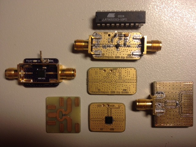
- HMC431 VCO module with shielded can (top of can not shown)
- A simple breakout board for SOT86/Micro-X RF gain blocks. (Top centre) This could be used with various MMIC devices in that package, from RFMD, Hittite, Mini-Circuits or various other manufacturers, they're all pretty similar. This board provides coupling capacitors, bias tee, power indicator LED, current limiting resistor in the MMIC supply rail, and a few decoupling capacitors. The passive values can easily be changed to suit different devices, so it's a generally usable module. An input attenuator is provided on this board so that the output power can be kept within the amplifier's linear region if the input power is too large.
- HMC717 LNA breakout board (bottom centre).
- Two different Wilkinson dividers, one of which uses a coplanar waveguide architecture (with top groundplane) and one of which uses more a microstrip approach (no top copper pour, fatter tracks compared to CPWG for the same given impedance.) We'll see if they exhibit any performance difference.
- 20-DIP chip provided for scale reference.
I made these boards with no solder mask at all - for a few reasons.
(a) Because the thin dielectric layer of solder mask between the metal and the air introduces a slight error (admittedly it is small) into the physics (for impedance and width calculations etc) because it is not accounted for in the model.
(b) To see if the board fab would have any issues with it. (No.)
(c) Because it makes it easy to see where all the signal traces are, makes it easy to shunt extra components between the signal tracks and the groundplane (eg. to add extra bypass capacitors), to cut the tracks and hack the boards in other ways, eg. adding extra attenuation, if the need arises.
(d) Because it looks good. OOH SHINY. The slight disadvantage is that the solder looks slightly "messy" (although there aren't any shorts) where it spills across the ENIG groundplane.
I did put a small region of solder mask underneath the 16-pin LNA, because with the 16-pin 0.5mm pitch QFN device I wanted to ensure it soldered successfully without any shorts or problems. (I haven't tested it yet, but to visual inspection it's good.)
Mixer boards are coming, but they haven't arrived yet.
Discussions
Become a Hackaday.io Member
Create an account to leave a comment. Already have an account? Log In.
Are you sure? yes | no