Design Principles:
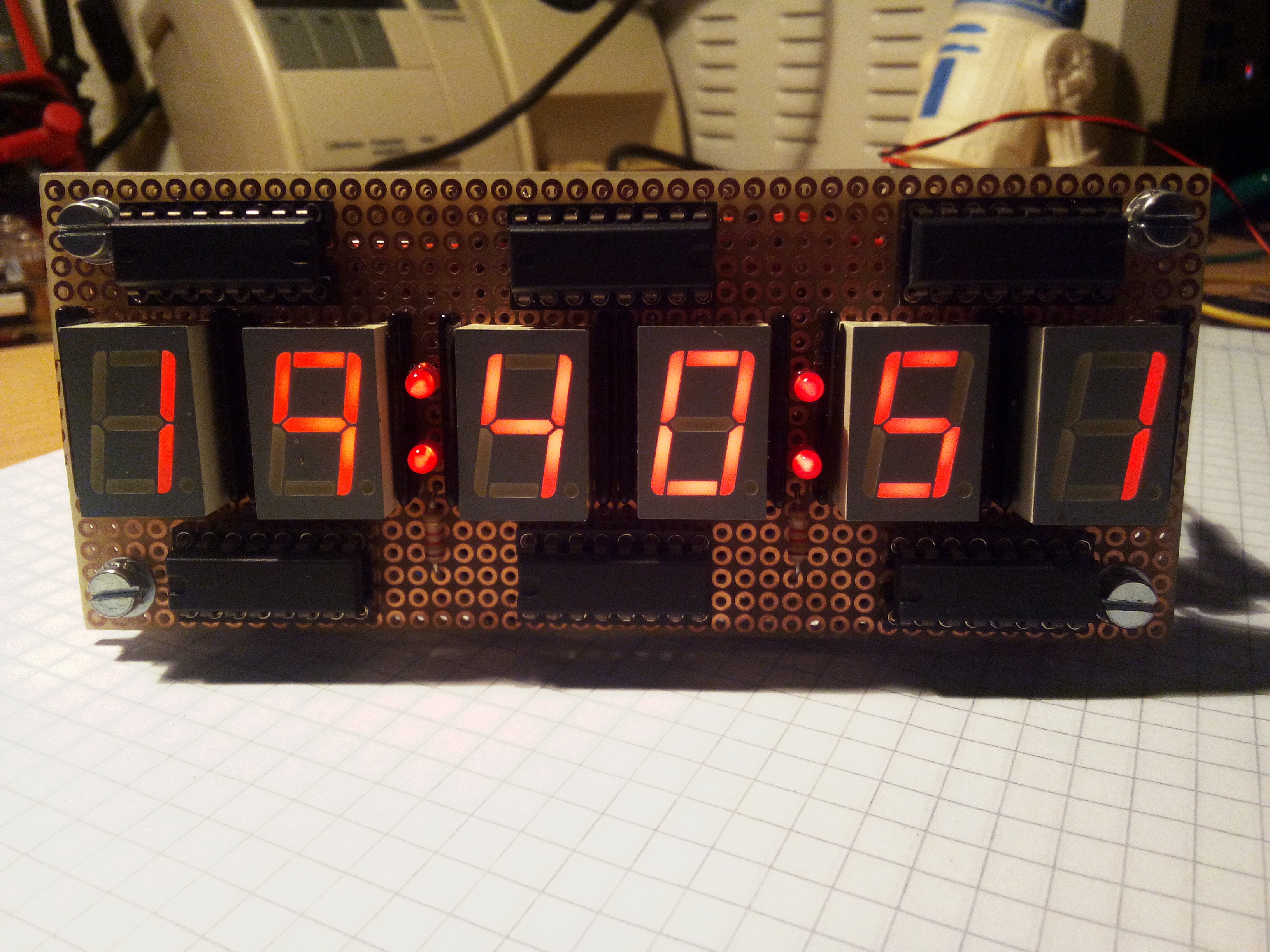
* clock with hours, minutes and seconds display, 24h format
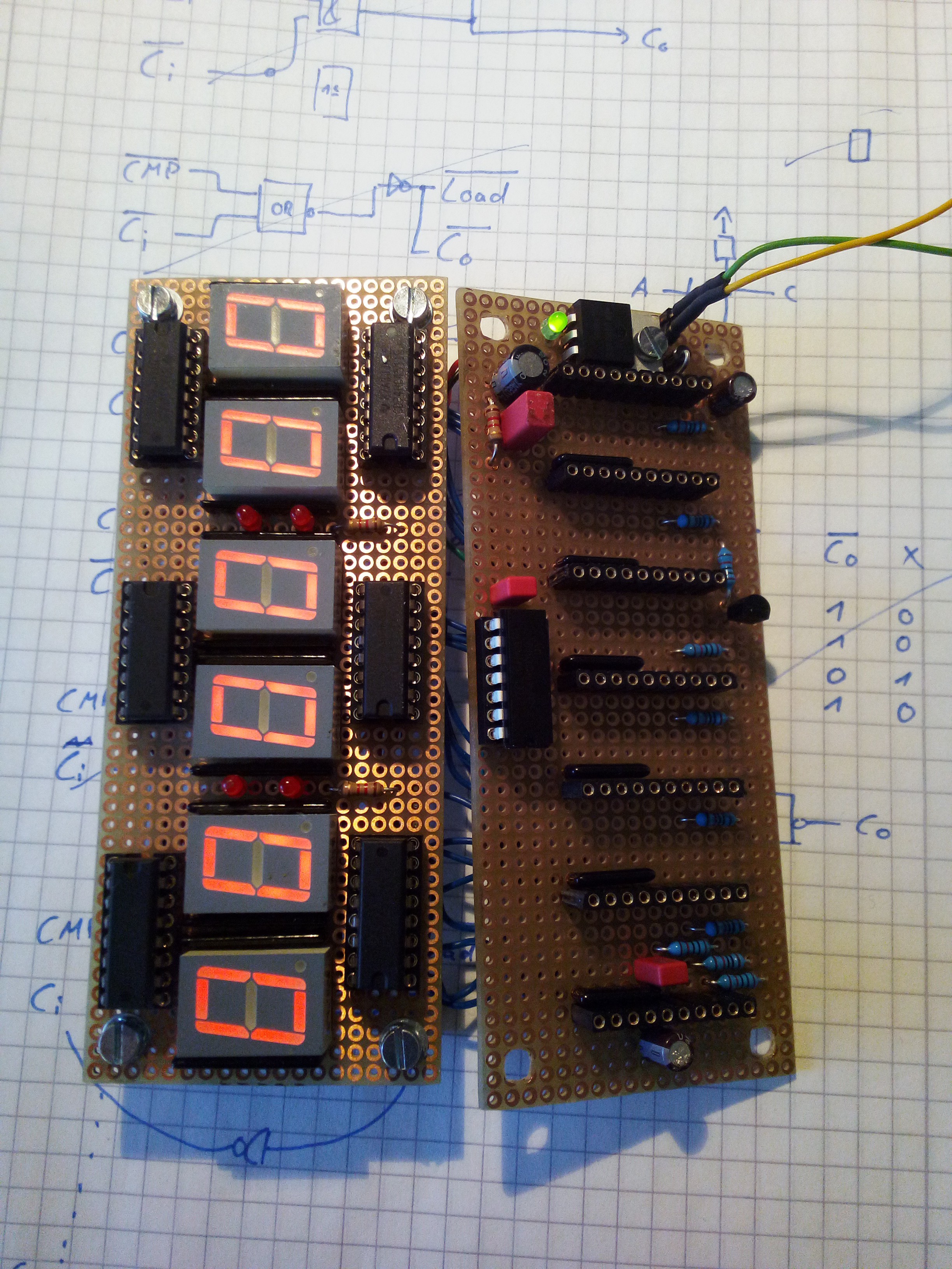
* 7-segment display to have the nice 70s/80s charm
* everything is driven by a single 1Hz clock
* everything runs on 5V
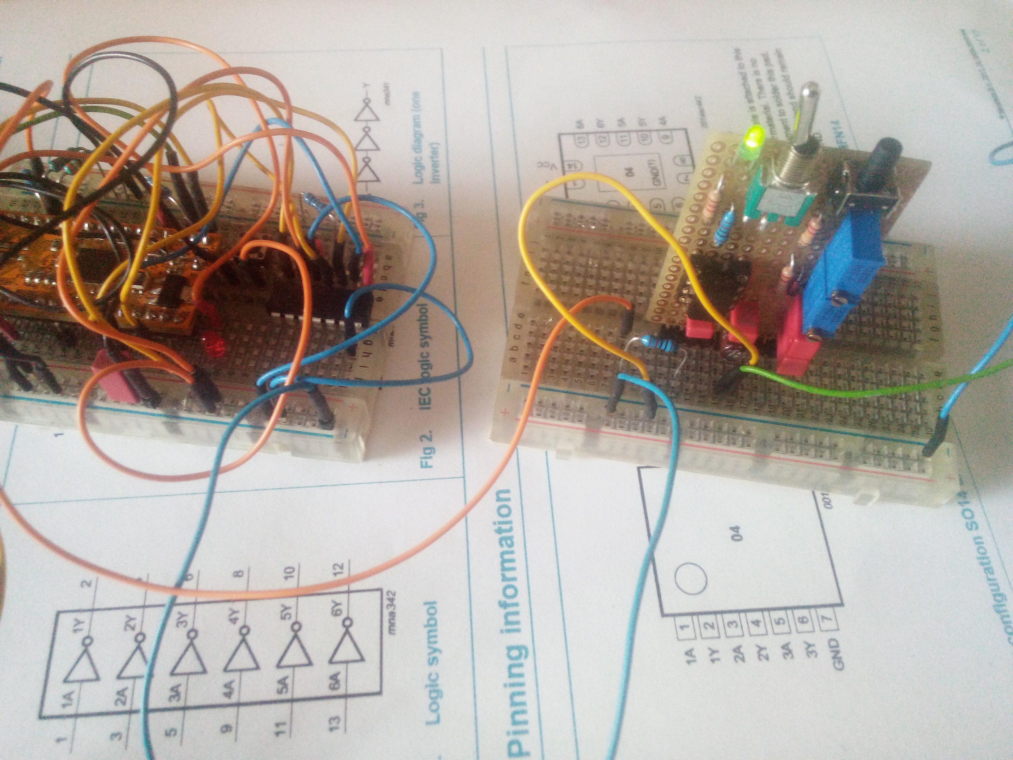
* use discrete-logic only - no "hidden" AVR or something like that
* use the stuff I have in my shelves
* solder-friendly parts only
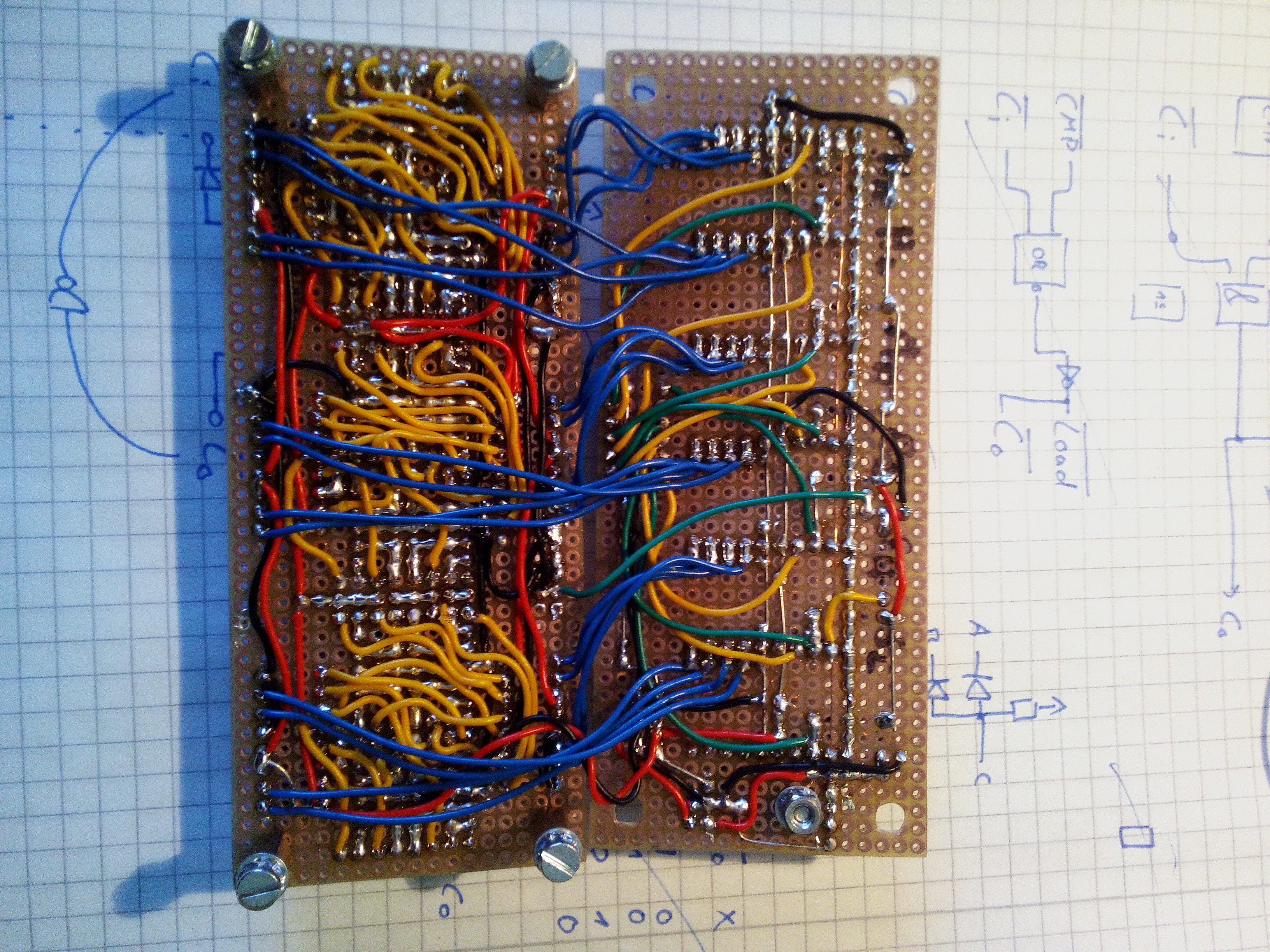
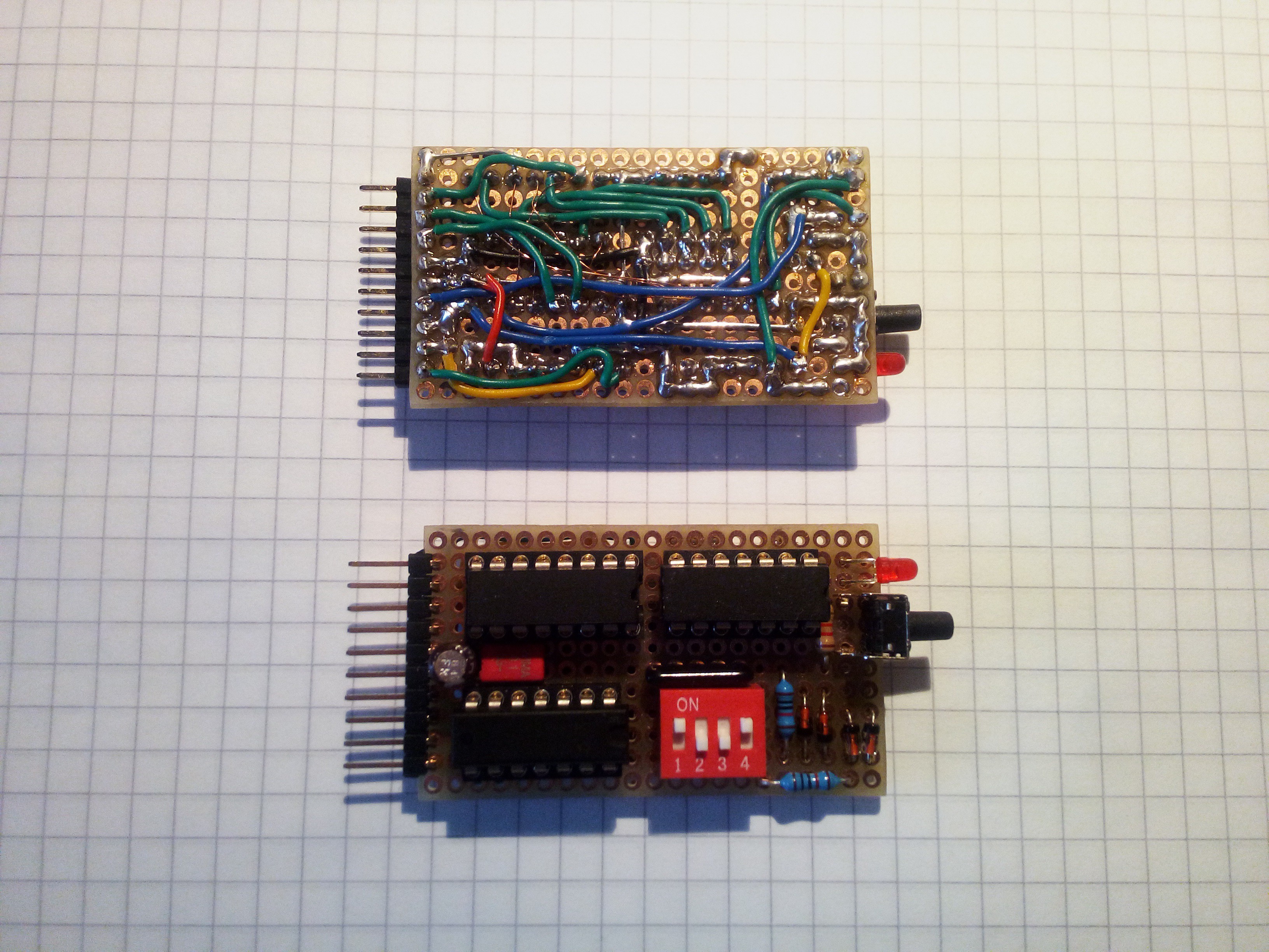
* use drilled boards instead of messy breadboards - no PCBs
* simple architecture
* suitable as project for a rainy (or Corona-lockdowned) weekend
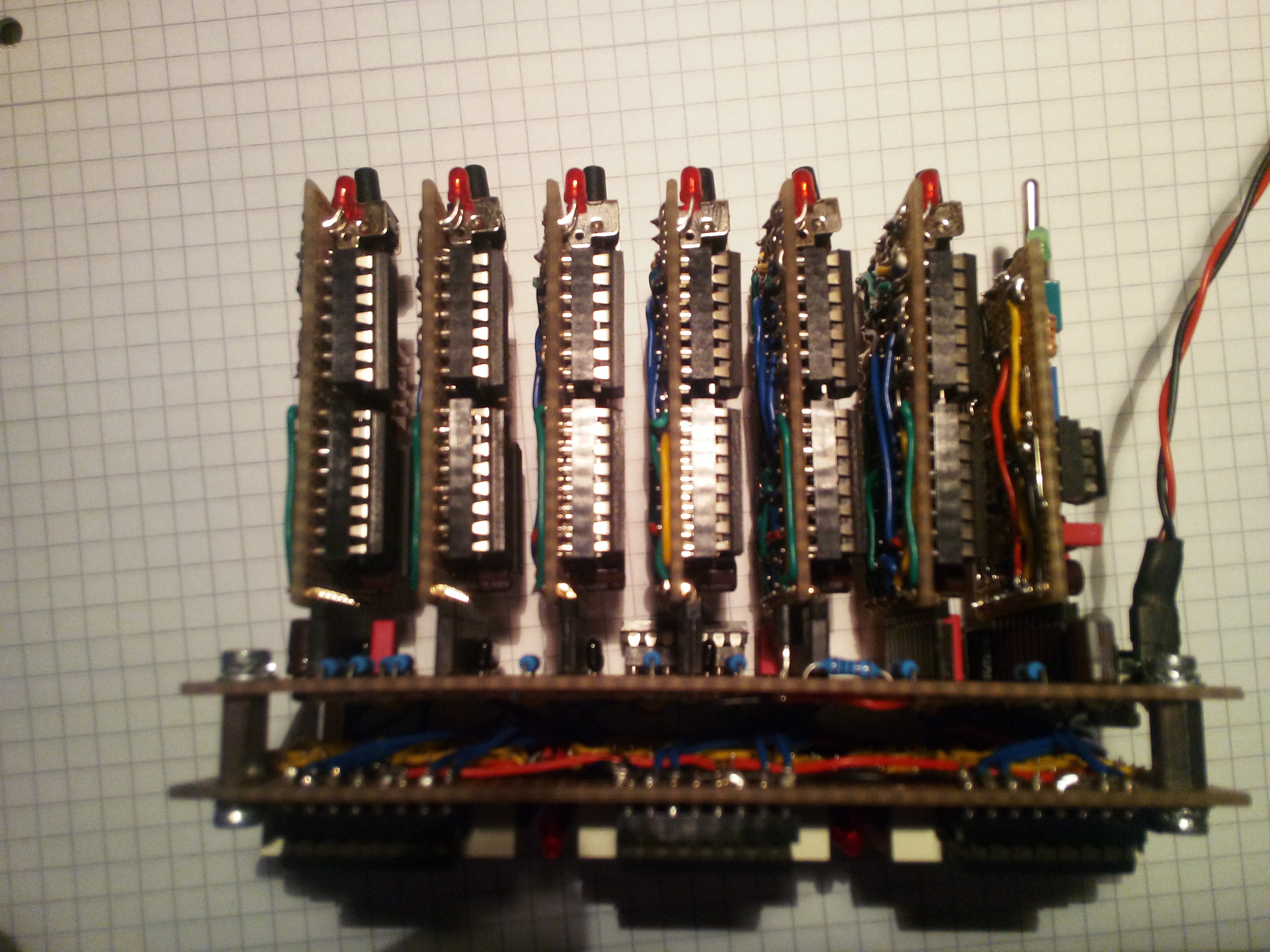
* modular setup, so I can replace things if I mess something up
Architecture
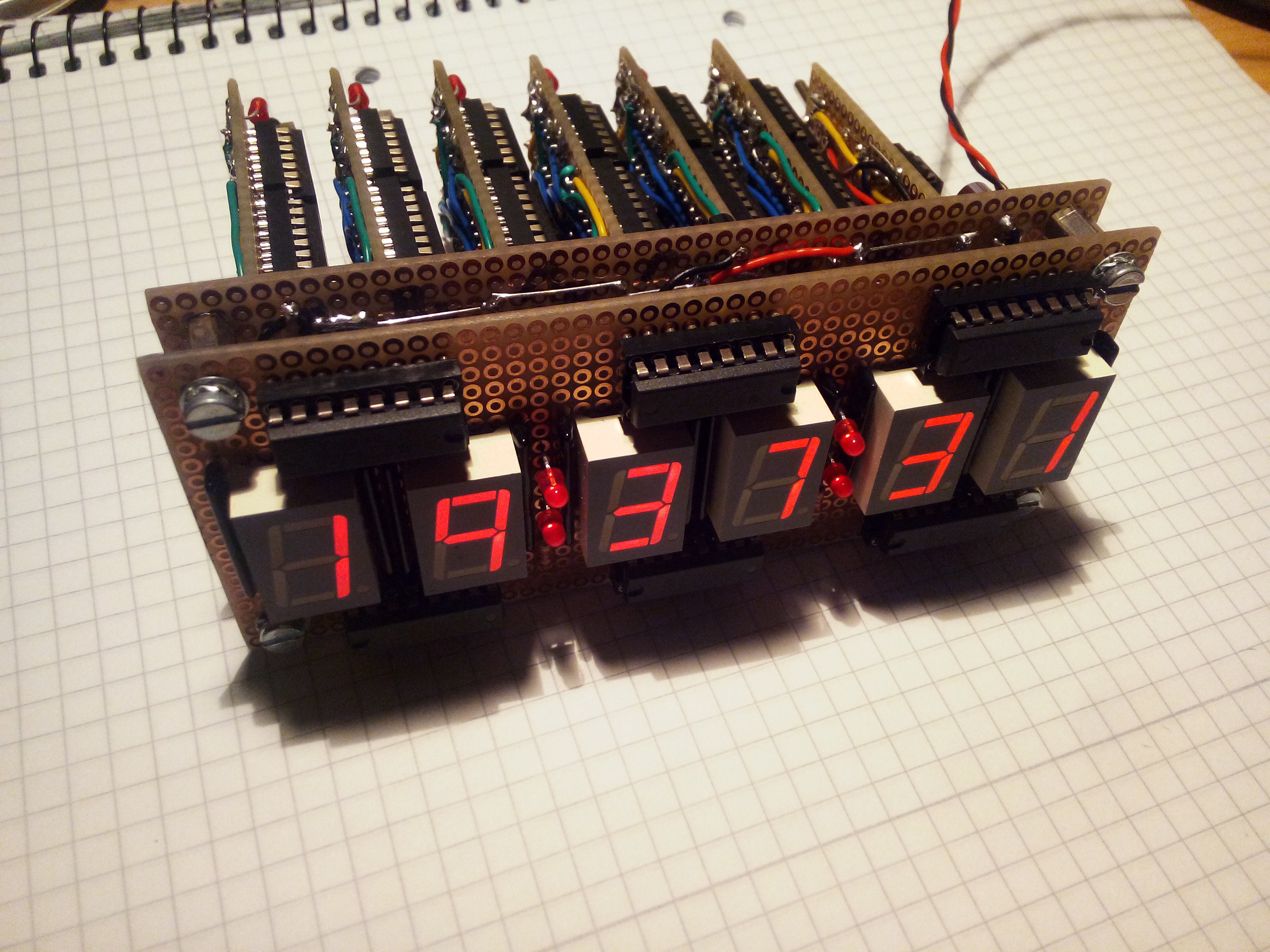
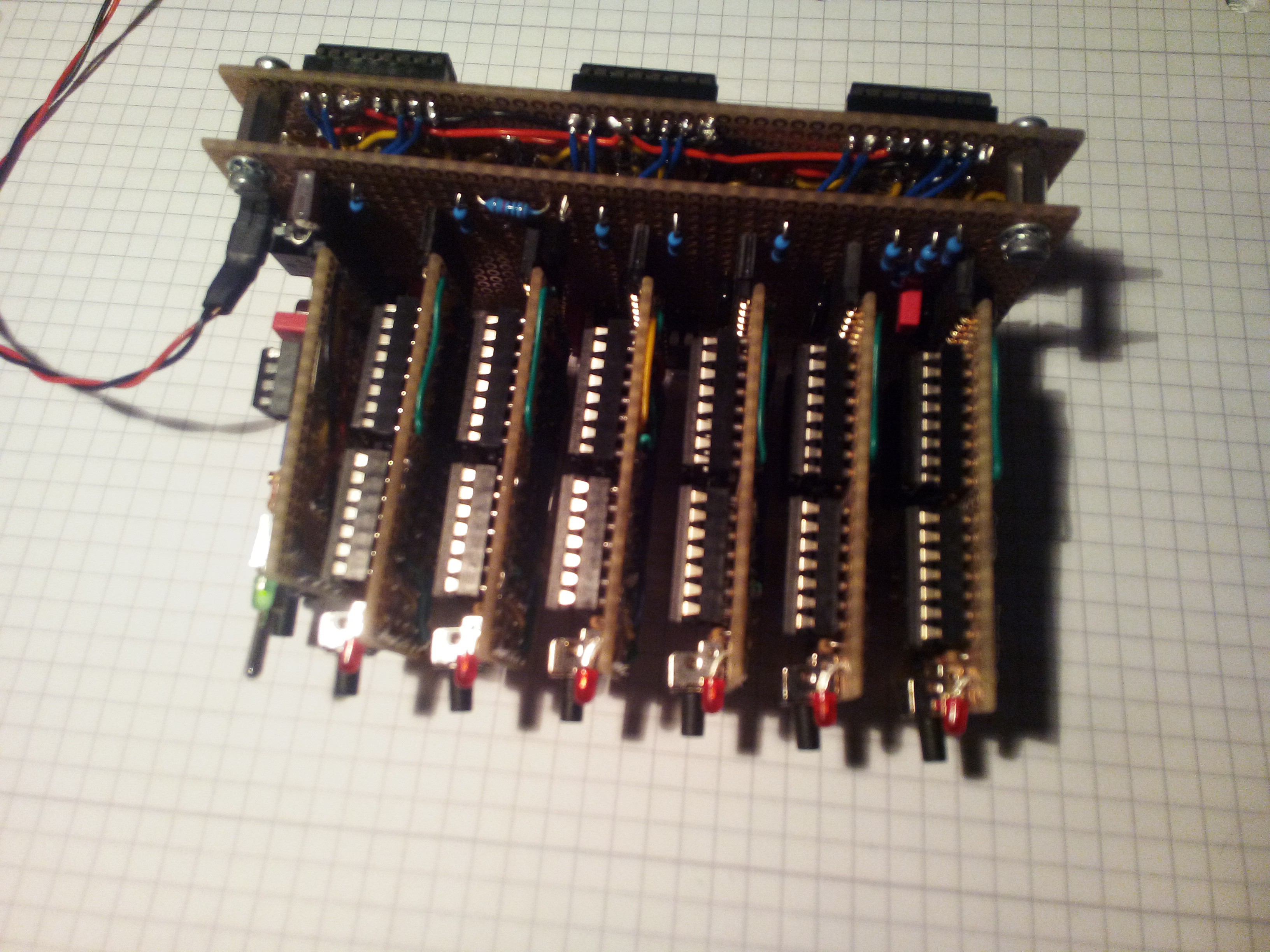
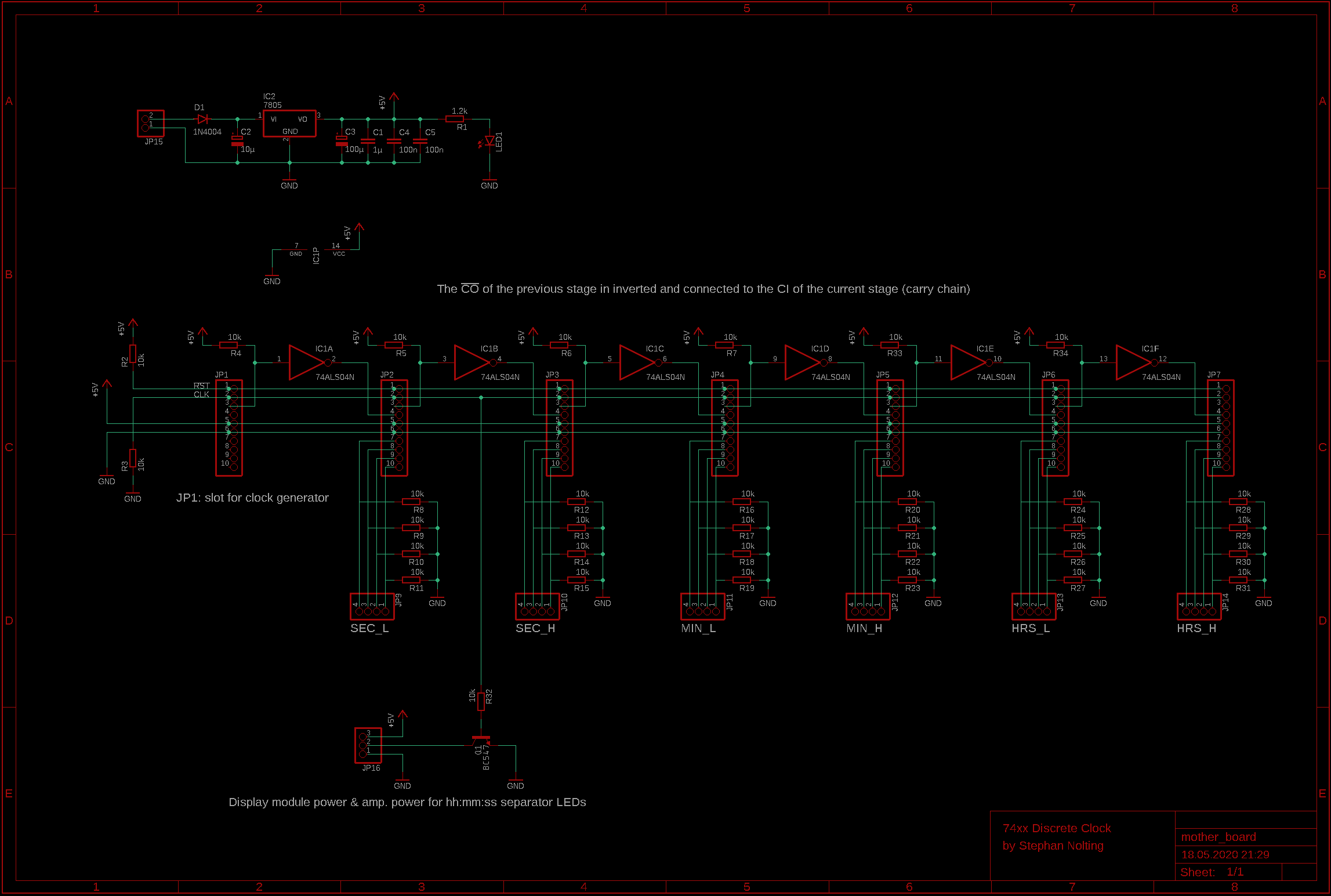
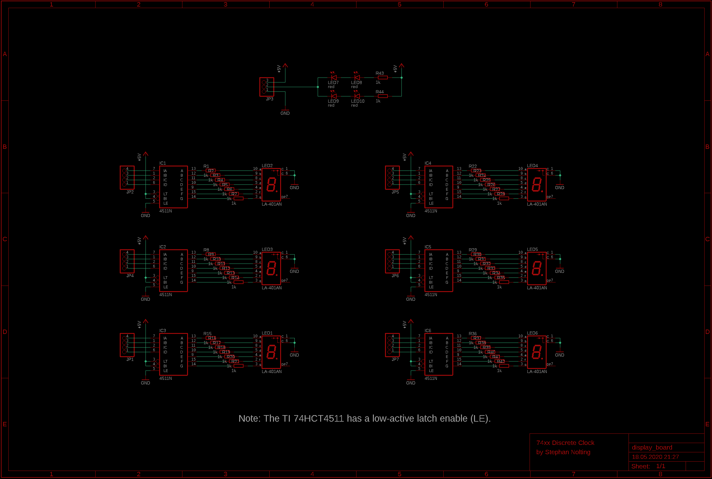
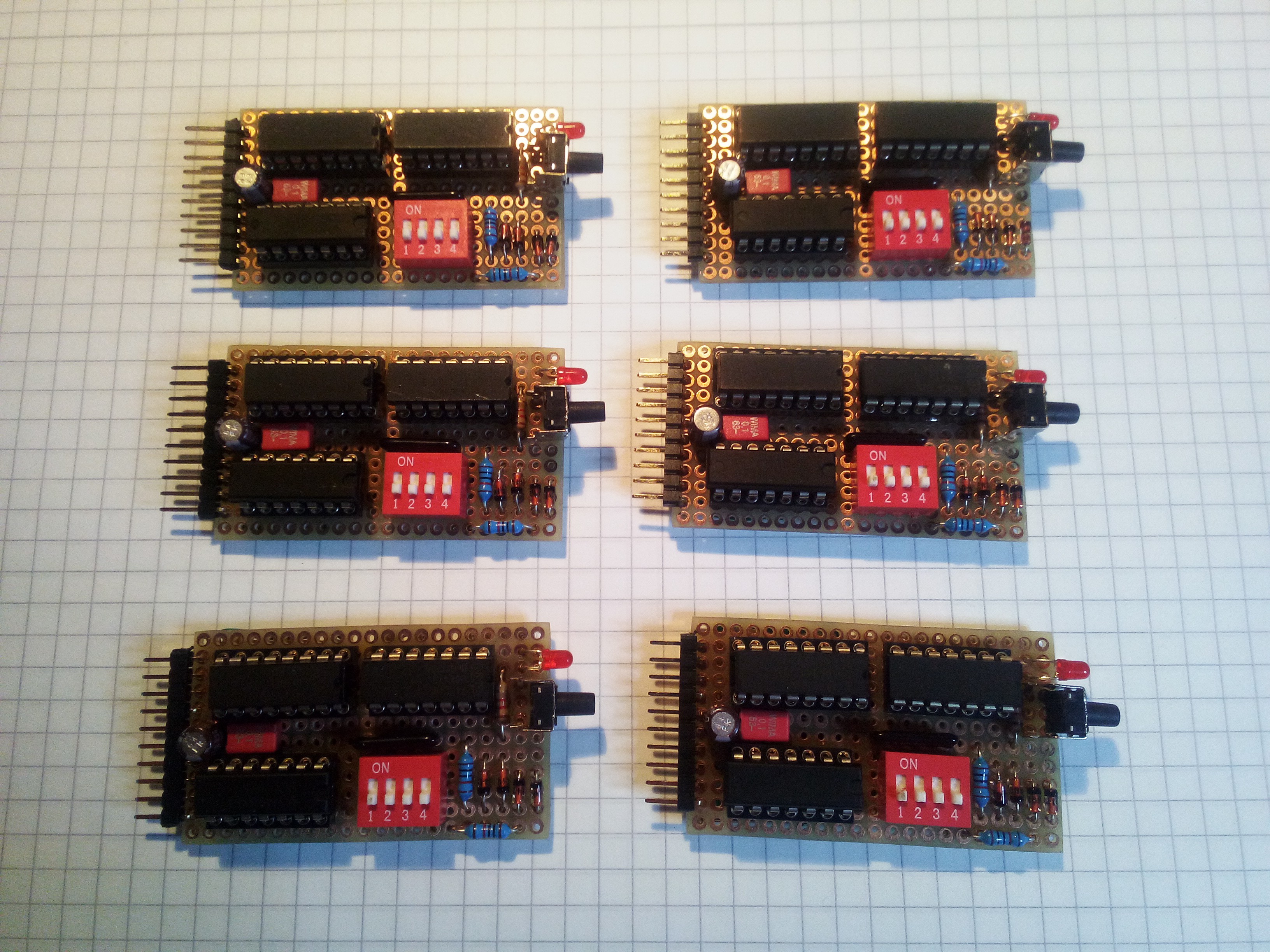
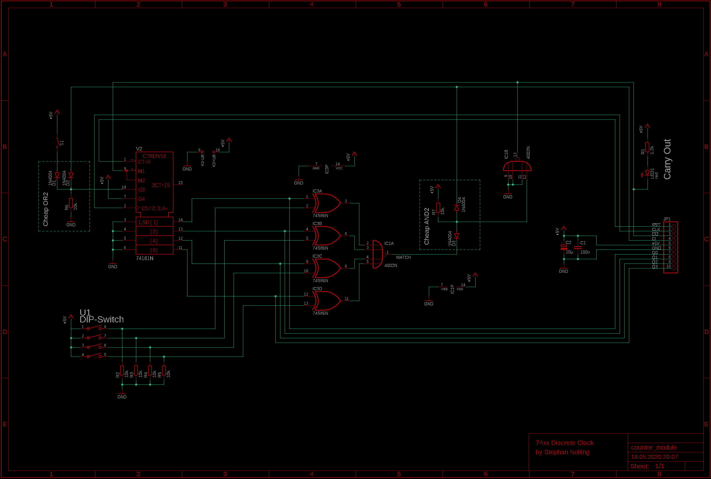
The clock uses 4-bit binary counter ICs (74HC161) for counting hours, minutes and seconds, which are interconnected in a classic ripple-carry scheme. The output of the counters is decoded to drive classy 7-segment displays. There are 6 counter modules, which are plugged into a motherboard. This motherboard provides the power supply and interconnects the counter modules with each other and also with the display board. The display board contains the decoders and the actual 7-segment displays. All modules are clocked by clock module, which generates the 1Hz base clock.
Hardware overview:
* 6 "programmable" counter modules
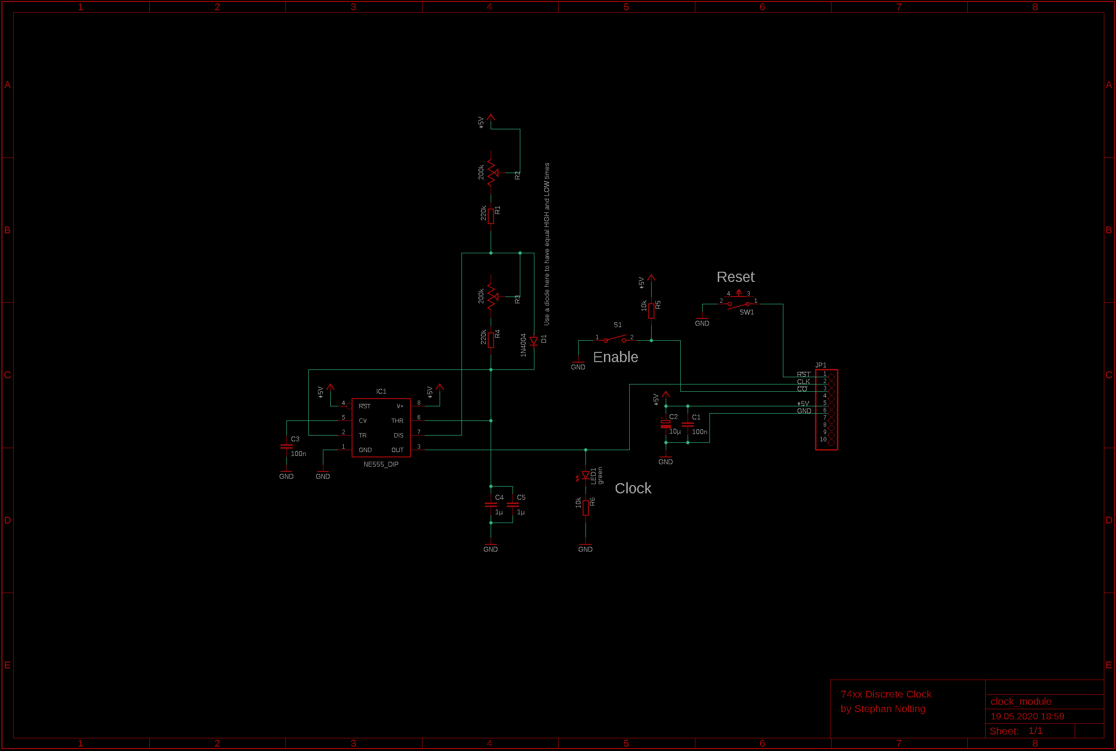
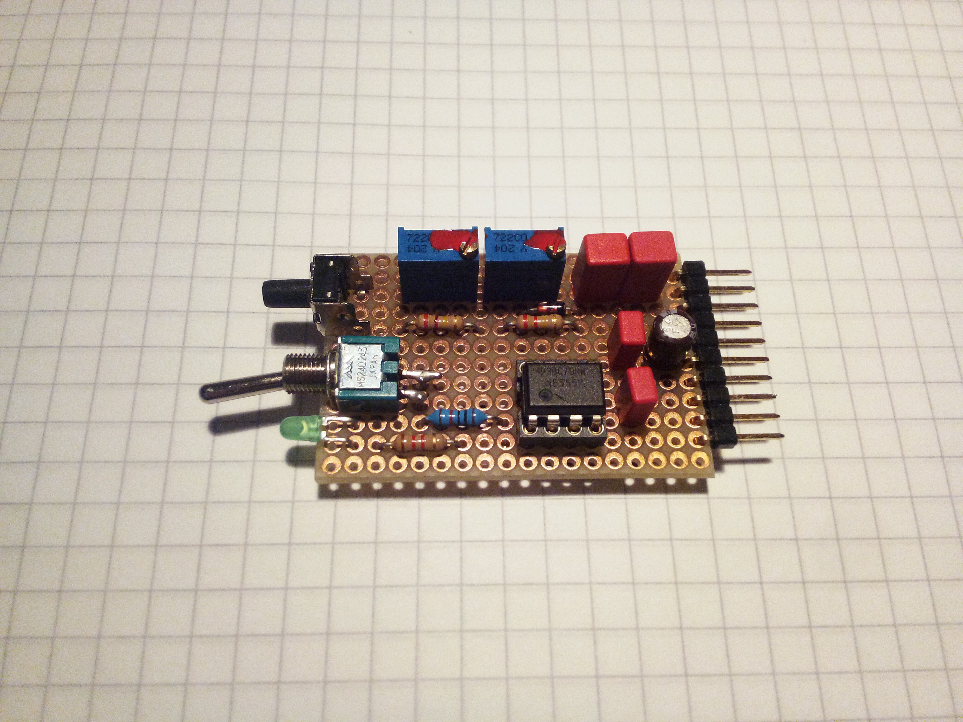
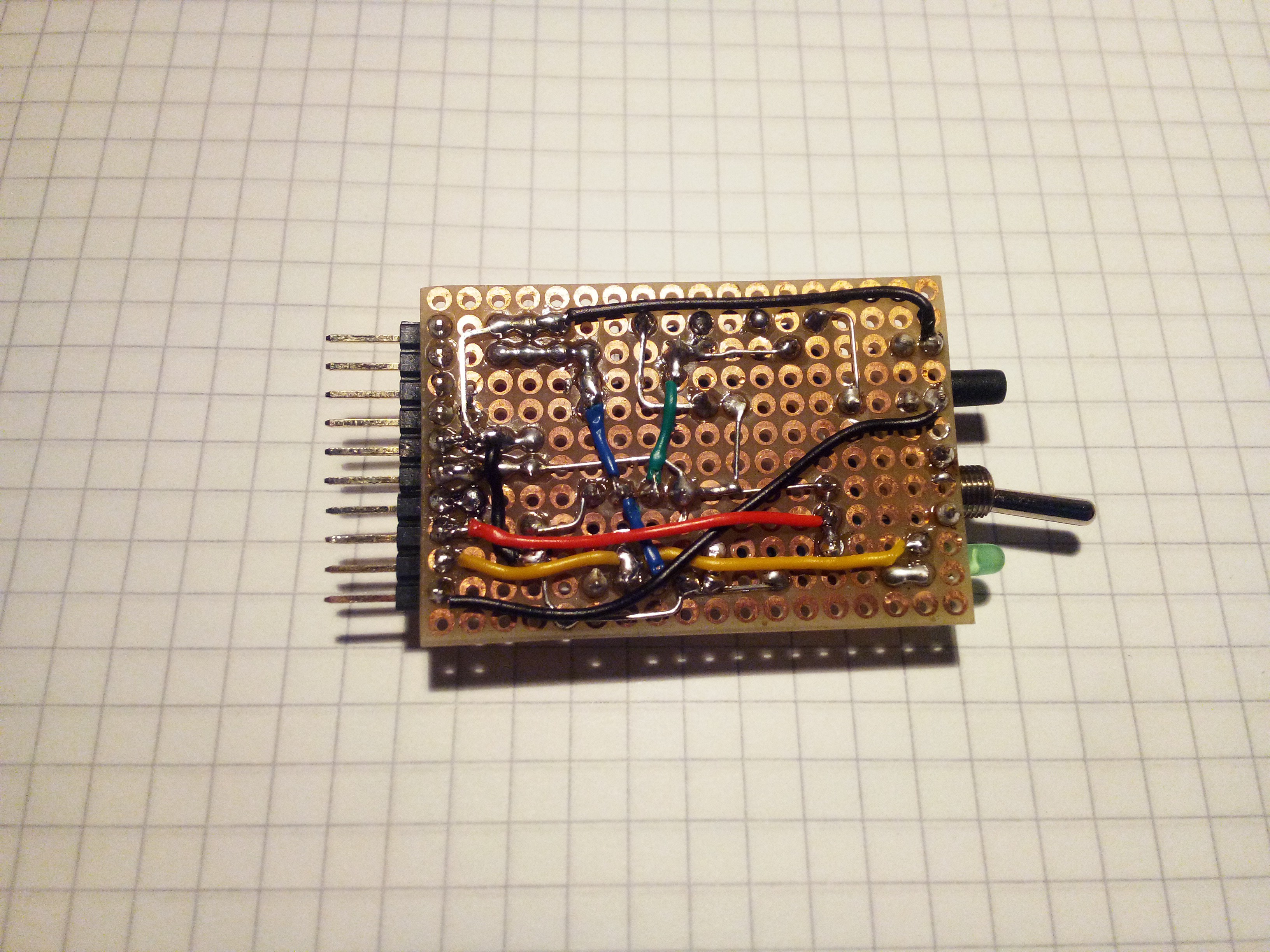
* 1 clock module to generate the 1Hz clock
* 1 display board with 6 7-segment displays
* 1 mother board to connect everything
 Scoops
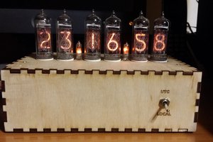
 Marek Więcek
 Douglas Henke
 Ken Yap