Close
0%
0%

Melba I

Melba I is an implementation of the Apple I from parts in my collection.

Public Chat
Similar projects worth following

I would be lying if I said that I've always wanted an Apple I; the first Apple product I ever lusted after was the 1990 Mac IIfx or (more realistically) the Macintosh LC.

The Apple I is of historic interest though, as the product that helped launch one of the most influential companies in the world, with impact on economy, culture, industrial design and much more. As such, I feel that I should have some practical experience with it.

A real one is out of the question; if I had the (probably) $2M required to buy one, I'd rather buy a fancy car. There are replicas and emulators out there. Some replicas are built using the exact same, now obsolete parts as used in the original. Other replicas uses microcontrollers to emulate the video interface, something I feel is like putting Tesla alloys on an original  '59 Mustang, An emulator will not provide enough "feel", that hardware will.

I really don't want to hunt down some unobtainium parts and TTL-chips with a 1976 date code, or implement Woz-magic in a microcontroller, so I guess I must implement my own Apple I clone. :)

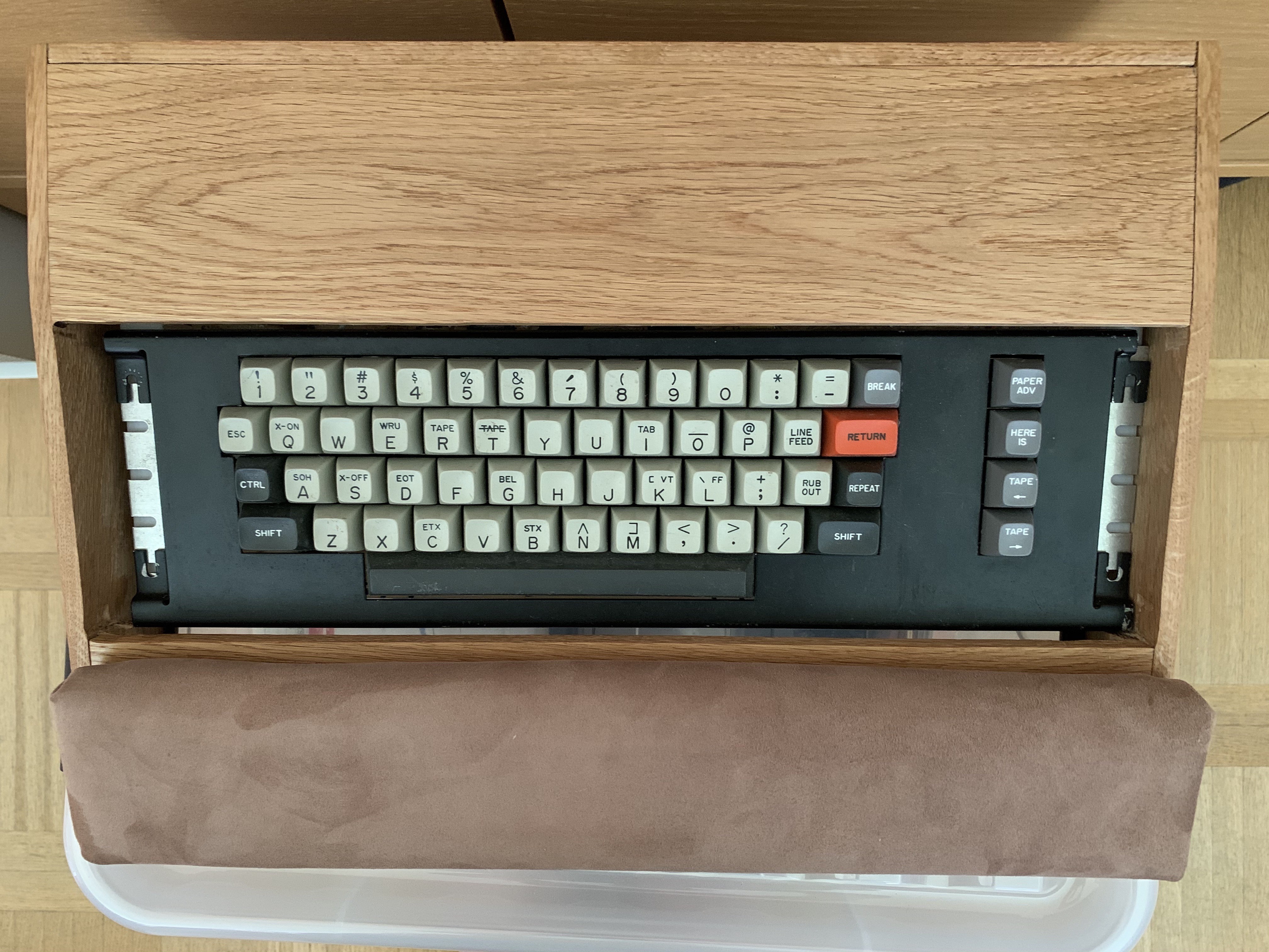
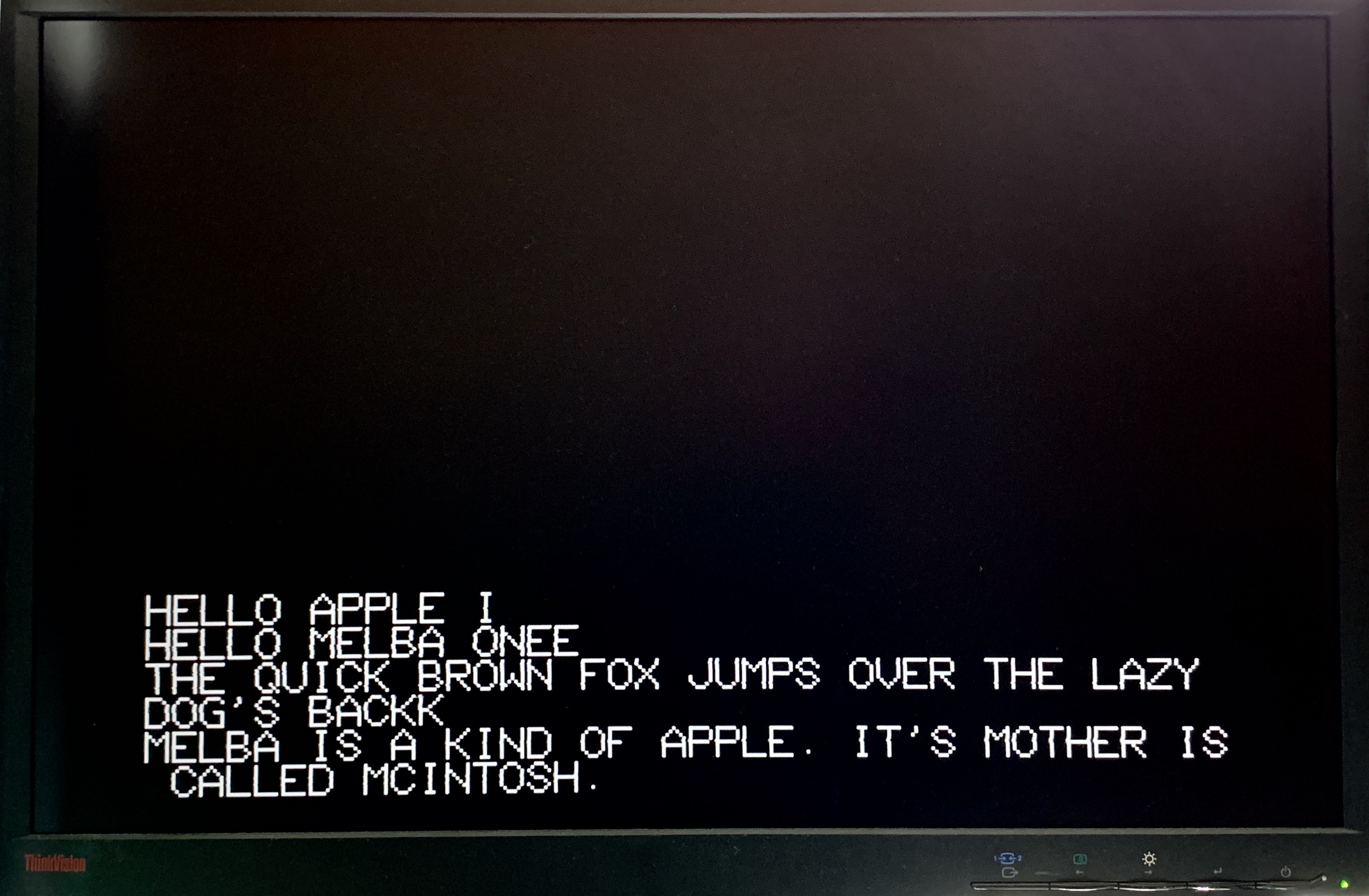
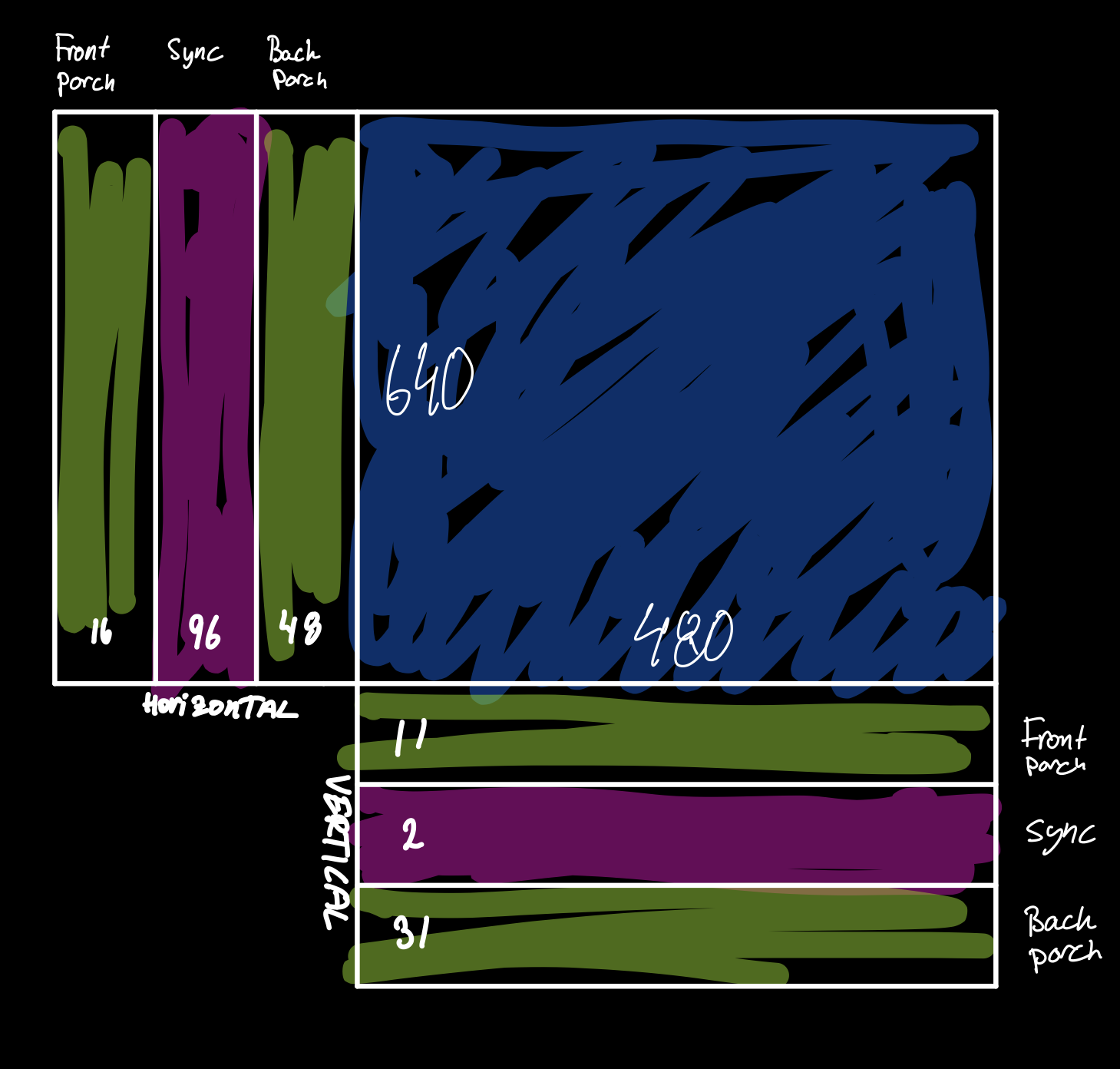
The Apple I is a very basic computer (I was going to write rudimentary computer, but where's the pun in that?). It has only the bare minimum needed to be a computer; CPU, memory and some IO. The IO is connected to what makes the Apple I and Apple I; the glass TTY.

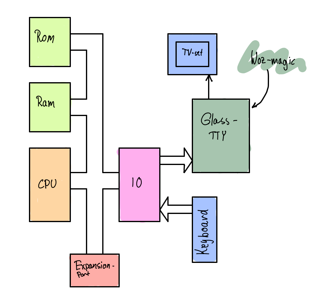
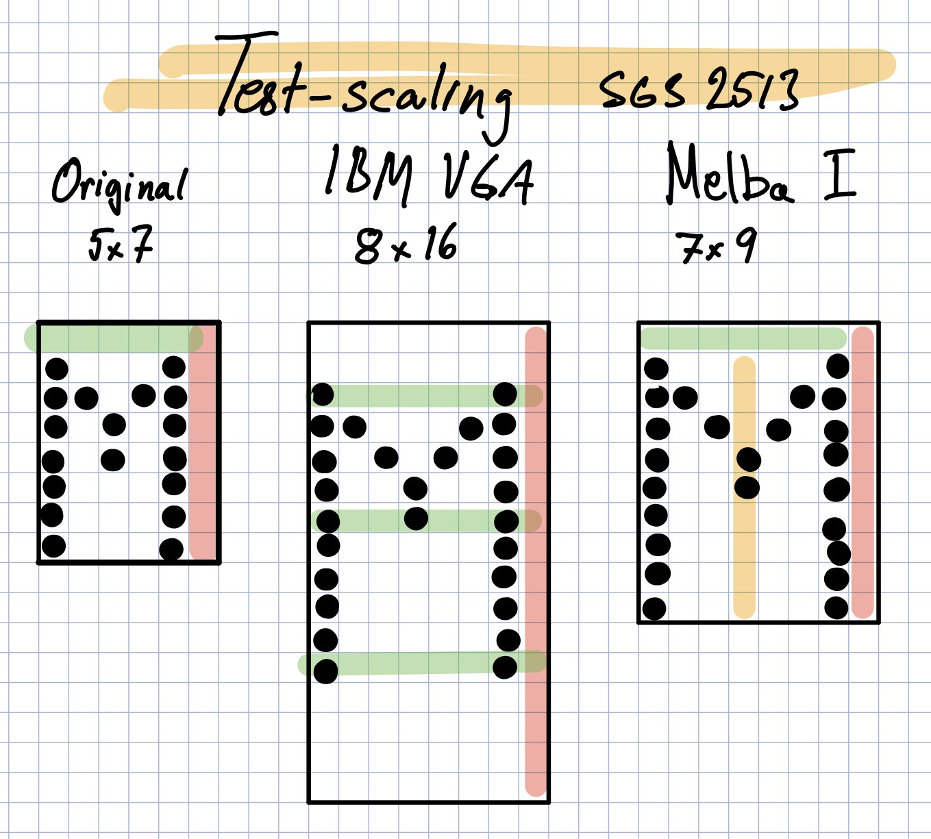
This piece of Woz-magic replicates the behaviour of a teletype, a keyboard and a printer that communicates with a computer, but on a television set. It shares some of the limitations of a real tty as well; you can not delete a character once written to the paper, and the cursor can't be freely positioned, and will not blink.

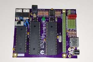
The computer came as a pre-assembled PCB, requiring only a case, keyboard and a power supply. This surely must have been interesting to people wanting to do mostly software, as the expandability was very limited, with the only expansion slot usually taken by the Apple Cassette Interface.

The project will be split into three phases:

  1. Requirements and research (done, mostly this text)
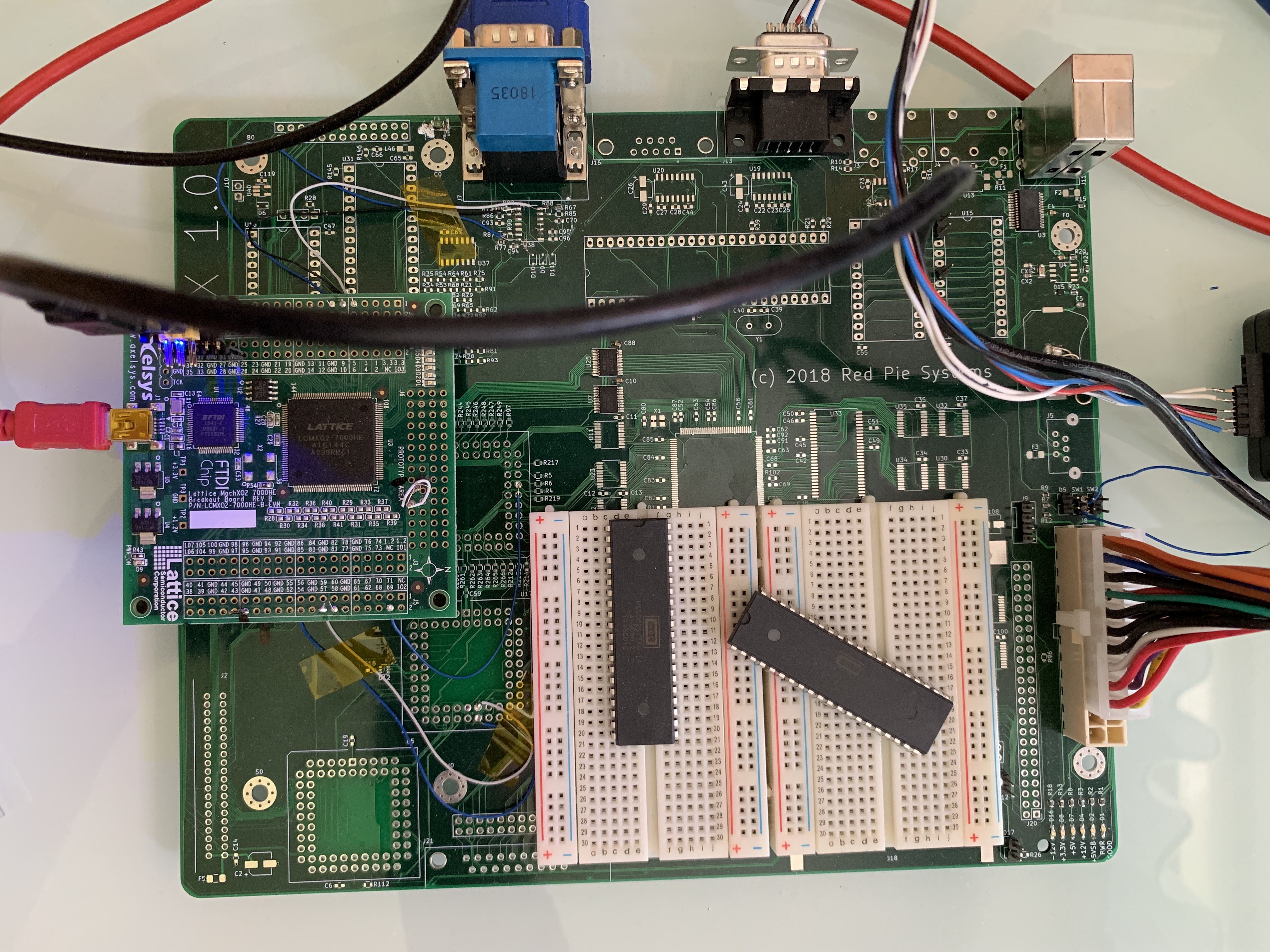
  2. PoCs
    1. TTY
    2. Complete system
    3. Cassette Interface
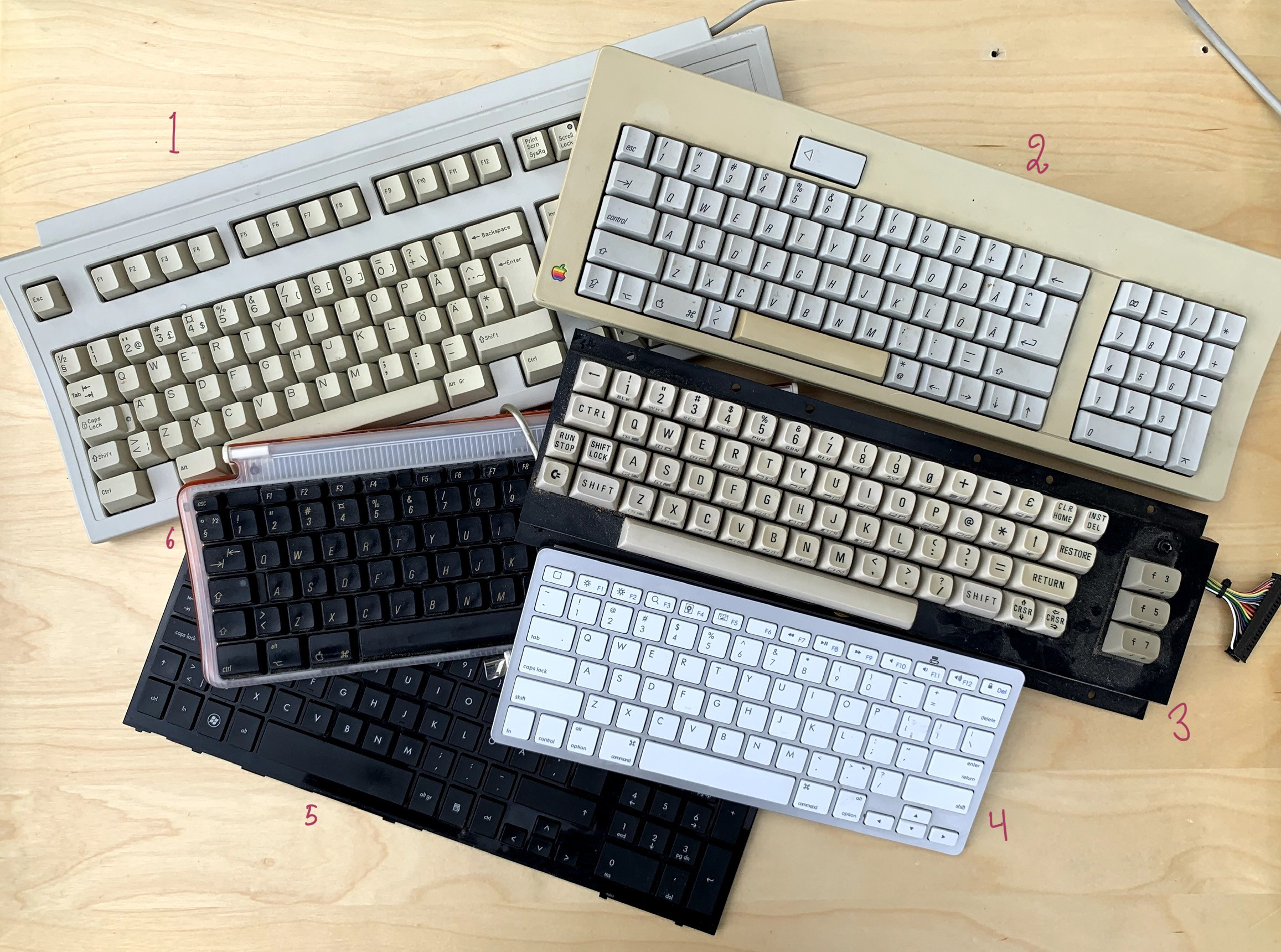
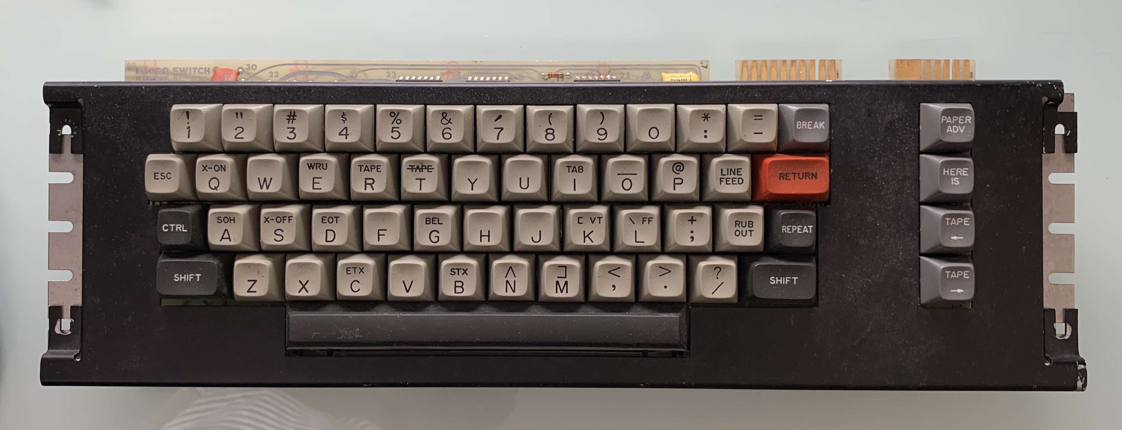
  3. Final design with case and keyboard

Melba_I_schematics.pdf

Schematics with most bodes marked.

Adobe Portable Document Format - 583.85 kB - 07/30/2020 at 16:06

Preview
Download

Melba_I.zip

KiCad project with all PCB-files.

Zip Archive - 582.54 kB - 07/30/2020 at 16:00

Download

micro switch keyboard.vcp

ViaCAD Pro model of keyboard and case.

vcp - 1.21 MB - 07/20/2020 at 12:50

Download

fn8x10.zip

Binary and intel-hex font

Zip Archive - 1.42 kB - 05/23/2020 at 13:20

Download

sgs2513 upscale to 7x9.pdf

SGS2513 font and an upscaled version for Melba I

Adobe Portable Document Format - 2.04 MB - 05/22/2020 at 11:21

Preview
Download

  • Theory of operation

    Christian Bjelle07/30/2020 at 18:27 0 comments

    A block diagram of the Melba computer is shown below, and looks pretty similar to the first page of the schematic. 

    The 6502 CPU executes instructions from the RAM with some minor help in decoding the address from the CPLD. The PIA is used to read the keyboard and write characters to the Video Terminal inside the CPLD.

    At first boot, however, the RAM contains random garbage, and no executable code. To make the CPU do useful work; we have to fill the RAM with a Woz-monitor and the Apple Integer BASIC in the correct locations. These has been stored inside a small SPI EEPROM, 25LC640A, and a module in the CPLD sends a read command to the EEPROM and reads the full 8192 bytes, while outputting the RAM address on the address bus and the data on the data bus. 

    Filling the RAM will have to be done while the CPU is still in reset and the CPU will also have to tri-state its buses. On the Z80, the buses are tri-stated during reset, but the 6502 needs a separate pin for this.

  • Board game

    Christian Bjelle07/20/2020 at 12:57 0 comments

    Using a bunch of development boards and breadboards in a computer is a recipe for disaster. If you sneeze it will probably fall apart.

    Also, the Mach XO2 breakout board hosts a gigantic CPLD that has a lot of resources that will just be wasted. The devices I have in my parts bin are much smaller, and are closer in size to the final resource usage. I decided to make a board for a Mach XO2 640, a W65C02S, 65C21S,  32k RAM and a serial 8k EEPROM. The Mach XO2 256 has the same pinout as the 64, but a few less IO-pins. By fitting a 74LV165 for the keyboard input, and assuming that a 65C21 would not be fitted in 256-board, the design could be adapted to accommodate the smallest Mach XO2 family member. That is, on the board and IO-wise. As it turned out, there weren't enough memory inside to support the video I needed, neither font ROM nor character ram, so only the 640 can be used. (I also forgot to buy any 74LV165)

    I started assembling the power supply parts. The power supply needs to have a -12V rail and a +5V rail for the keyboard. The -12 is also used for the cassette interface. These are made from jelly bean switcher parts, the MC34063, so that a simple wall wart can supply the power.

    There are also two separate 3.3V regulators fed from the +5. There is really no need to have two, but I wanted to split the load between two regulators to keep the heat down, since I had no idea about how much power the system would use under full load.

    Sadly, the switching parts did not work as expected, which may have something to do with me forgetting to buy 0805 0.2Ω (and 0.7Ω) resistors, and trying to bodge them together by stacking six 1.2Ω 0603 in their place.

    The -12V rail got very weird positive pulses on the output, and the +5V rail didn't oscillate properly, despite hacking on some load.

    I abandoned that board, and assembled a second board without the power supply part with the intention of going back and dig deeper into what was wrong.

    When the second board was assembled, I discovered that my Lattice device programmer was missing. Buying a new one is a proven method for finding a missing item, but has so far failed this time. 

    Since I really needed to program the CPLD on my new board, I had to find another way.

    Another development board to the rescue!

    The MachXO2 breakout board has a built-in JTAG programmer, and all you have to do is to disconnect the CPLD on that to be able to use it as a stand-alone programmer.

    I carefully cut the TDI and TDO traces, soldered in a pin-header in the J1 position, added jumper wires to my fresh board and was ready to go!

    The breakout board is still showing off its blinking-led demo.

    The setup worked surprisingly well, and after bodging a +5V wire to the VGA-connector to wake up the monitor, I had working video out! (again)

  • Boxing Day

    Christian Bjelle07/02/2020 at 12:38 0 comments

    After striking gold with the lovely 1974 keyboard, I wanted to make a suitable case for keyboard and computer.

    My inspiration came from the most easily accessible Apple I in the world. The image of an  Apple I at Wikipedia, with an identical keyboard to mine. The case in the picture has to house a real Apple and power supply. My PCB is a lot smaller, and I will use a modern power supply, so I can give my case slightly better ergonomics, with the keys further in and an area in the from to rest your hands.

    I didn't have any suitable material at home, but my local hardware store had oak in 8x90 mm in lengths of 2.5m.

    I made a 3d-model of the keyboard in ViaCad Pro, and started to roughly "build" a box around it. (Picture below)

    With the rough model in place, I rigged up a workspace in the garden with a miter saw and a small band-saw.

    I still hadn't decided how to join the corners, but just cutting the corners at 45°, applying glue and taping the pieces together was the intended simple solution.  However, on a spur of the moment change of mind brought on by some feeling with the band-saw, I went with a box joint. 

    I probably should have practiced a bit, but on the plus side, I got to try out some ways to hide my mistakes.

    To get a nice surface finish, I applied some oil.

    I also wanted a nice hand rest.

    The packing material for my 3d-printer was a plastic foam material, and had about the right size. I cut a channel in the foam for a wood core with metal threaded inserts, and wrapped it in a piece of inside-out leather.

     I'm not completely happy with the looks of the hand rest, but it might turn out right when the complete system is assembled.

  • A Key Note

    Christian Bjelle07/01/2020 at 08:44 0 comments

    To select a good keyboard for a project like Melba I is no easy task. The style of keyboard sets the look-and-feel of the entire system. At first I intended to use a PS/2 keyboard, with a MiniITX-PCB in a small PC box. That would loose some of the Apple-feel I was after, so I started researching the ADB-port, to connect an old Macintosh keyboard. Maybe a USB-port and a fruity-coloured iMac keyboard with a Pippin-style case in a matching color would be better?

    As I dug deeper in my collection of computer pieces I considered

    1. PS/2
    2. ADB
    3. C64
    4. Chinese wireless apple-knockoff
    5. Laptop keyboard
    6. USB

    All of these would require some sort of microcontroller to adapt to the keyboard interface in Melba I, and I still don't want to use one just like that, especially since USB and Bluetooth would require some pretty beefy one.

    Then I found the perfect keyboard in an old treasure chest in the garage. I really don't know where or when I bought it, but I think I've had it since the mid 80s. Manufactured in 1974, it has no less than four keys labled "tape" with some variations.

    After some googling, I found that it was from a TI SILENT 700 MODEL 733, and seems to be a good fit for an Apple I-clone. The link also provided details about the pinout on the card edge connectors.

    Bitsavers.org has a complete scan of the original manual.

    Now I can start designing a suitable box, and start experimenting with the keyboard :)

  • Building a PIO

    Christian Bjelle06/19/2020 at 19:06 0 comments

    I was preparing to plopp-in the big ICs when I realised that the PIO had mostly internal connections. Very few of the IO-pins were to connect to anything outside the CPLD, making a real chip unnecessary tedious to wire up.

    As I had expected to write a 6821 in Verilog sooner or later, I immediately started hacking.

    The ports A and B are almost identical, and only differs in their behaviour when reading from an output port, where port A reads from the pin and port B reads from the output register.

    To avoid writing two nearly identical modules, I used the ifdef-statement to get two instances of the same module with slightly different behaviours. If someone can suggest a more elegant solution, please comment below.

    `ifdef TASTE_LIKE_PORT_A
    	      // Port A behaviour
    	      // Read output pins directly (i.e. only input-pins)
    	      busOutputRegister_next = portInputRegister;
    `else
    	      // Port B behaviour
    	      // Splice output data with input data
    	      busOutputRegister_next = (portOutputRegister & ~dataDirectionRegister) |
    				       (portInputRegister & dataDirectionRegister);
    `endif
    

    All signals in a 6821/6520/65C21 are relative to the trailing edge of the E-clock, with one notable exception. I was happy to use E as clock for my c6821 until I started implementing interrupt control for CA and CB IO.

    Interrupts are by their nature asynchronous, and 6821 can be programmed to react to either positive edges or negative edges, and I was searching for the most verilogish way to detect either when I came across this article. 

    I realised that I had to synchronise the inputs with a clock, but the E-clock was so darn slow that  most short interrupts would likely be lost, and even worse was the fact that this module instantiated in my CPLD would live by a clock that was different from all other clocks on the "SOC".

    I went back and added a fast clock and synchronised all my inputs, E, CA1, CB1 and even the ports PA and PB. (which is why the input pins in the code above is portInputRegister; it is registered at that point.)

    All in all, I'm pretty happy with my little PIO.

    I've also started looking at a suitable keyboard and a case-design, but that is a story all by itself.

  • Finally some progress!

    Christian Bjelle06/05/2020 at 11:12 0 comments

    I've finally gotten to a point where the video logic accepts data from the UART and displays it on the screen.

    Lessons learned

    It is very hard to debug something if you are unsure anything works

    At first power-on, the only thing that appeared working was some LEDs and a blinking white cursor on the screen. This at least told me that the base board was working, VGA-wires connected correctly and the module producing the sync signals correct, and that a video signal was produced.

    Sending serial data produced no response at all. The scope verified that serial data was indeed received, but sent to the wrong pin (as half expected), but even sending it to the right pin made no difference.

    Methodically working upwards in the hierarchy from the parts that worked, I was soon stuck again. There was no output from the generated EBR-ROM.

    Do not assume that a tool does what it claims

    It turned out that IPexpress was happy to create a EBR-based ROM, populated with a binary file, without warning about that the ROM was actually empty! As I trust the tools provided by Lattice, this took a few hours to sink in.

    The binary font-rom-file is generated from a ascii-text source format and converted by a tool to an intel-hex. I had produced a sister-tool to generate Verilog-source for a ROM, and that got me past that hurdle.

    module font_rom (input wire clock, 
                     input wire [11:0] address,
                     output reg [7:0] data_out);
    
        always @(posedge clock) begin
            case (address)
                // @char(0x20) {
                // @char(0x21) {
                12'h211: data_out = 8'b00010000;  // '   0    '
                12'h212: data_out = 8'b00010000;  // '   0    '
                12'h213: data_out = 8'b00010000;  // '   0    '
                12'h214: data_out = 8'b00010000;  // '   0    '
                12'h215: data_out = 8'b00010000;  // '   0    '
                12'h216: data_out = 8'b00010000;  // '   0    '
                12'h217: data_out = 8'b00010000;  // '   0    '
                12'h219: data_out = 8'b00010000;  // '   0    '
                // @char(0x22) {
                12'h221: data_out = 8'b00100100;  // '  0  0  '
                12'h222: data_out = 8'b00100100;  // '  0  0  '
                12'h223: data_out = 8'b01001000;  // ' 0  0   '
                // @char(0x23) {
                12'h231: data_out = 8'b01000100;  // ' 0   0  '
                12'h232: data_out = 8'b01000100;  // ' 0   0  '
                12'h233: data_out = 8'b11111110;  // '0000000 '
                12'h234: data_out = 8'b01000100;  // ' 0   0  '
                12'h235: data_out = 8'b01000100;  // ' 0   0  '
                12'h236: data_out = 8'b01000100;  // ' 0   0  '
                12'h237: data_out = 8'b11111110;  // '0000000 '
                12'h238: data_out = 8'b01000100;  // ' 0   0  '
                12'h239: data_out = 8'b01000100;  // ' 0   0  '
    
          ....
    
    
                12'h5f9: data_out = 8'b11111110;  // '0000000 '
                default: data_out = 8'h0;
            endcase
        end
    endmodule


    Do not forget the relative timescale of signals when simulating 

    With the ability to produce hard coded text on the screen, I could now turn my attention to the UART. One of the issues was that the remote echo, created by sending back the received character, was running away, sending an unending stream of repeating garbage text.

    The problem here was that when I simulated the UART, I used a strobe-signal (to start sending the character) that was a few clock-cycles wide. In reality, the strobe produced by the receiver was high after a character was received, and went low only when the stop-bit of the next character was received, and then went high again. The effect was that the transmitter always believed that the data on the in-port was new...

    If I had used a reasonably scaled strobe-signal, I would have noticed the problem long ago.

    The biggest problems are the dumb ones

    After a lot of new stimulations and hard tests, I realised that the garbage-text I got looked a lot like the garbage you get when the baud-rate is set wrong. 

    Bingo! With the baud-rate set to 19200 bps, rather than the expected 9600 it works!

    NeXT Step

    There are a few minor bugs, like advancing the cursor while still writing a character to RAM, which produces a duplicate of the last character above the cursor, or that the B looks pretty ugly. 

    I'll fix those 😎

    The biggest thing for the next iteration will be the...

    Read more »

  • Demo One - first breath

    Christian Bjelle05/24/2020 at 12:07 0 comments

    After implementing the video logic in Verilog, and simulated using Icarus Verilog, I decided tro move to hardware.

    For this demo, I'll target the MachXO2 breakout board, that has a MachXO2-7000HE, integrated programmer, USB-UART and most of the pins on pads. It does not have footprints for any of the ports I need, so I will put it on a carrier-board made from a failed project PCB.

    In my parts bin, there are a couple of Mach XO2 256 and 640 LUT chips, and the design will easily fit in any of those. The 640-part has some block-RAM that can be used as ROM that is lacking in the 256-part, which means I will probably use the 640-part in the final design.

    Before putting the MachXO2-BOB on the carrier and doing some modifications I flashed the on-board chip with my design just to verify that I didn't screw something up.

    The only way to see if it was alive was to probe with a scope.

    Notice the proper probe-grounding :)

    Indeed, there are sync-signals! V-sync is shown in the picture below, and should be exactly 60 Hz, but is a bit off, depending on the internal oscillator of the Mach XO2.

    Since the screen is blank after reset, there should be no video signal, but as can be seen in the video below, there is a periodic signal. That signal is the cursor blinking. The Apple I did not have a blinking cursor, but I added one, as one of the very few extensions.

    Next up is the carrier board. I need to locate suitable ground- and power-points, as well as the VGA-signal-pads on the board.

  • Video with a bit of Ma^H^HLogic

    Christian Bjelle05/22/2020 at 19:08 0 comments

    The video sub-system consists of three logic modules; Timing Generator, Video Generator and the TTY logic and also a Font ROM and a shared, dual port Character Code Point RAM.

    Not shown in the figure below, is a shared buffer-offset. It is updated by the TTY-logic and is read by the Video Generator to enable automatic scrolling.

    For the first PoC, I've also implemented a UAR (Universal Asynchronous Receiver) that will receive test-text from a computer.

    The text from the UAR enters the TTY-logic as a series of 7-bit bytes with a strobe-signal. The logic calculates the next RAM-address and stores the character there.

    Displaying text

    Before diving into the Video Generator, it is important to take a look at the Timing Generator (TG). The TG takes a clock signal and counts pixels on a row, and scan lines. At the appropriate time it asserts the V-sync and the H-sync signals to synchronise the monitor to the video signal.

    VGA was created when monitors had CRTs in them, and CRTs works by moving a beam of electrons across a coating of phosphor, making it glow in proportion to the intensity of the beam. The beam is moved using magnetic fields, and those have some inertia, making them unstable when changing direction. To avoid visible distortion, each scan line has some invisible period, and there are some invisible lines at the end of each frame-scanning as well.

    The invisible period is itself split into three parts; Front porch, Sync and Back porch.  For the TG, the sync pulses are asserted in the purple interval, and the Video On signal is asserted in the blue interval in the figure below.

    In the blue interval, the TG provides a horizontal counter, 0-319 and a 0-23 row counter with a 0-9 scan-line counter to the video generator.

    The Video Generator, VG uses these counter and combines with the buffer-offset from the TTY-logic to create an address for the character RAM. The data in the character RAM is an ASCII value that forms an address together with the vertical scan-line counter into the Font ROM.

    The Font ROM provides one scan-in worth of font data, which is shifted out to the video port.

  • Screen resolution

    Christian Bjelle05/22/2020 at 10:53 0 comments

    I want an authentic feel as far as possible, but I will draw the line at the video interface. While b&w CRT sets were commonly available in 1976 (ahh, those were the days...) now they are pretty rare. I will compromise and give my clone an interface to a modern screen. While the ultimate goal is a DVI or HDMI connector, the PoC will use VGA.

    As a side benefit from using a modern screen, the Melba I can also support a couple of different themes; while-on-black, black-on-white, green-on-black and amber-on-black. Implementing amber on a VGA port is a bit more complicated than the others, since amber is a non-integer mix of R, G and B, so I won't test that in the PoC.

    Screen resolution

    The Apple I had a 40 characters wide and 24 lines tall display. The 64 characters were defined in a commonly available ROM, ("character generator") the Signetics 2513. This ROM contained the bitmaps of upper-case letters, digits and some punctuation. Notably lacking were |, { and }, wich would make writing C-code an interesting exercise. Adding a row of blank pixels between each character and an empty scanline between rows would give a smallest possible resolution of 240x192 pixels. While there are some graphical display modules available with that resolution, it would not look in any VESA resolution.

    After some internal debate, I decided to scale the original font to a 7x9 size, that with the same character and line spacing would fit perfectly in 320x240 (Q-VGA), that is very easily upscaled to standard VGA.

    I also tested to scale the font to VGA-size, but the 7x9 in an 8x10 matrix (Why do I get a Star Trek Voyager vibe here?) looked closest to the original.

    For easy addressing, the characters are aligned on 16-byte boundaries, even though only 10 bytes are used for each character bitmap.

View all 9 project logs

Enjoy this project?

Share

Discussions

infologics96 wrote 05/18/2021 at 06:18 point

This excellent website truly has all of the info I wanted concerning this subject and didn’t know who to ask. 

<a href="http://infocampus.co.in/angulartwo-training-in-bangalore.html">Angular Online training</a>

<a href="http://infocampus.co.in/angulartwo-training-in-bangalore.html">Angular 9 training in Bangalore</a>

<a href="http://infocampus.co.in/angularjs-training-in-bangalore.html">AngularJS Training in Bangalore</a>

<a href="http://infocampus.co.in/angularjs-training-in-bangalore.html">AngularJS Online Training</a>

<a href="http://infocampus.co.in/react-js-training-in-bangalore">ReactJS Training in Bangalore</a>

<a href="http://infocampus.co.in/react-js-training-in-bangalore">ReactJS Online Training</a>

<a href="http://infocampus.co.in/python-training-in-bangalore.html">Python training in Bangalore</a>

<a href="http://infocampus.co.in/ui-development-training-in-bangalore.html">UI Development training in Bangalore</a>

<a href="http://infocampus.co.in/ui-development-training-in-bangalore.html">UI Development Online training </a>

<a href="http://infocampus.co.in/web-designing-training-in-bangalore.html">Web Designing Online Training</a>

<a href="http://infocampus.co.in/web-development-training-in-bangalore.html">Web Development training in Bangalore</a>

<a href="http://infocampus.co.in/web-designing-training-in-bangalore.html">Web Designing Course in Bangalore</a>

  Are you sure? yes | no

Similar Projects

Does this project spark your interest?

Become a member to follow this project and never miss any updates