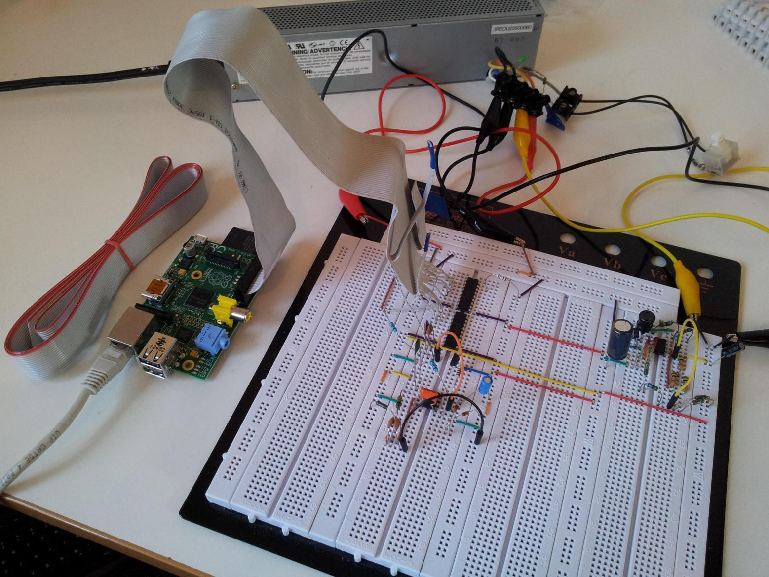
Close
0%
0%

Digital Stamp with Inkjet Printing

Adding digital to a stamp. Print anything anywhere on any plane, inkjetable surface.

Similar projects worth following
Stamping things is cool. The old rubber stamps are a bit static when it comes to new themes. And even if there is a decent amount of themes lying around, the one you want will be missing.

So here comes the digital stamp.

Presave a lot of themes and even templates. Templates can be enhanced by actual date + time (down to subsecond), consecutive numbering, and maybe weather or global positioning (would need extra parts/wifi). Or how about printing some tweets.

And the best thing: No thermal printing!
- No special paper needed
- No special labels to buy
- Not fading in the sun
- ...

Further use lies in easy substitution of label printers or just printing an adress directly on an envelope.

I will start with a simple setup as a proof of concept:
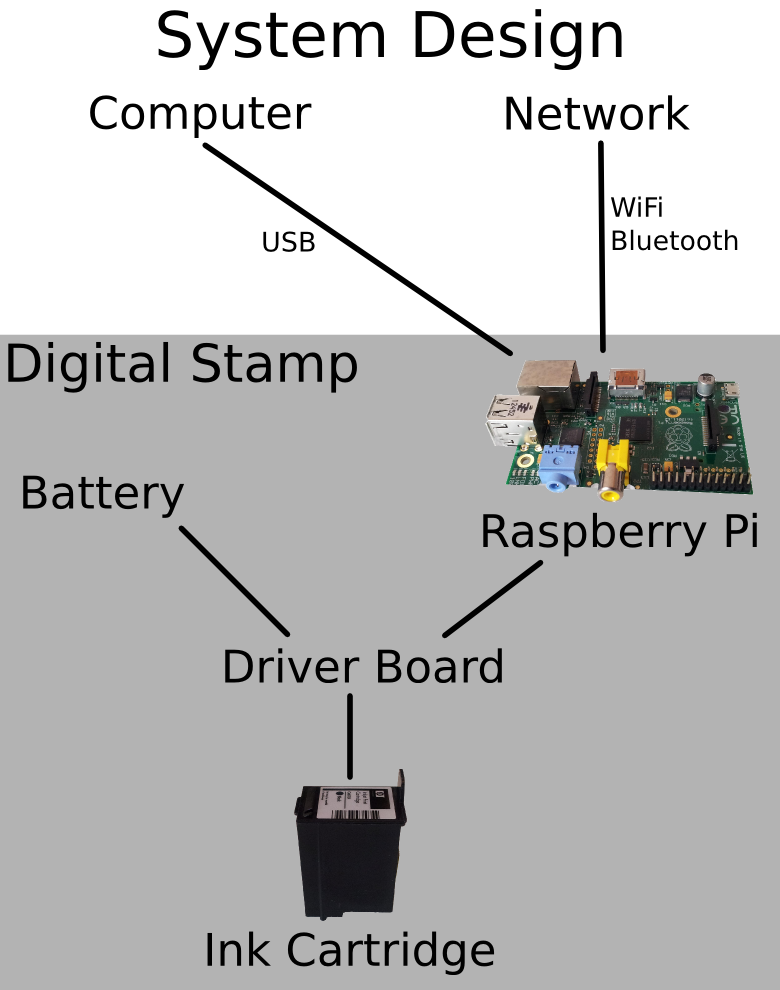
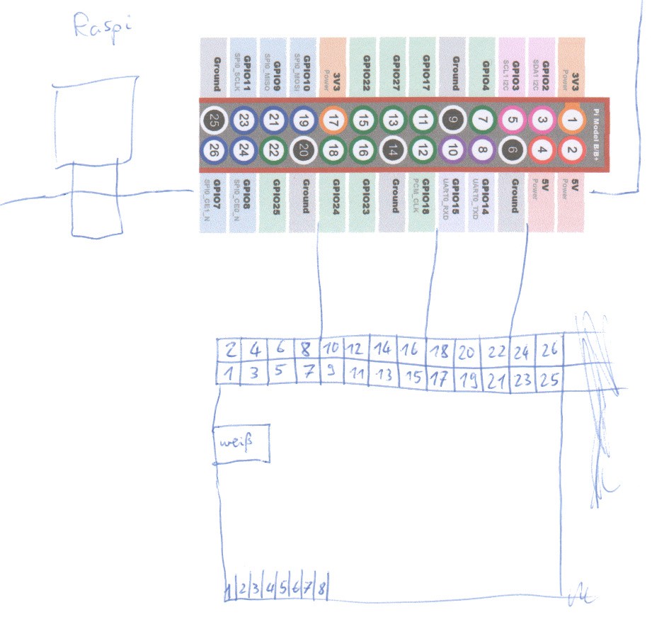
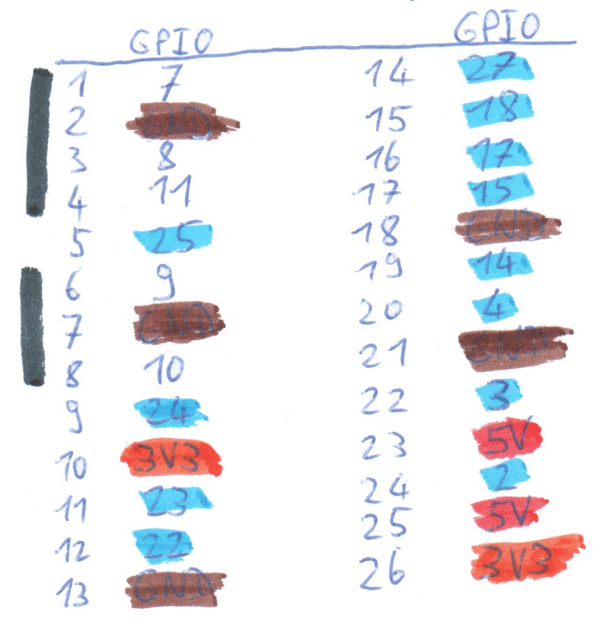
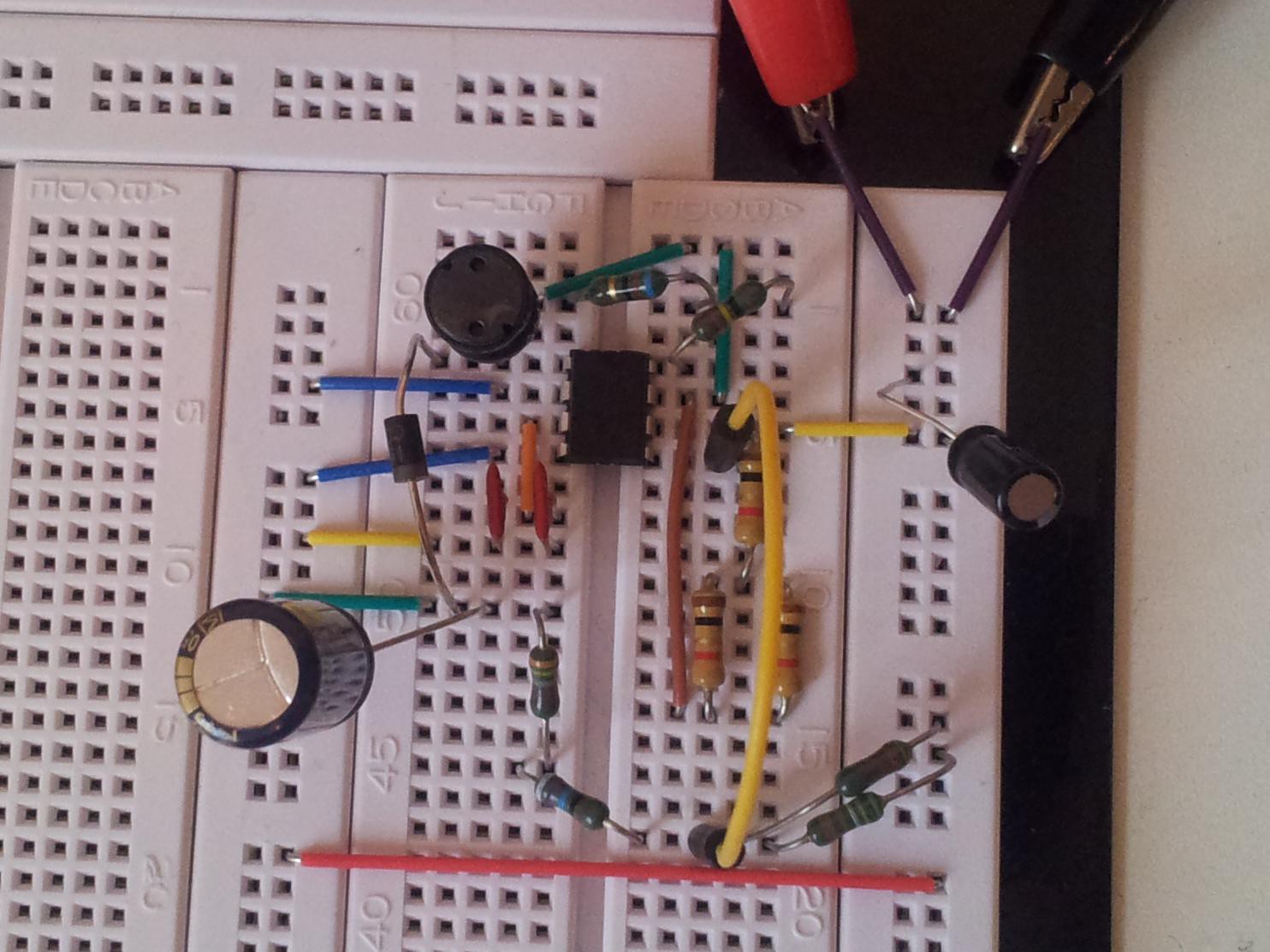
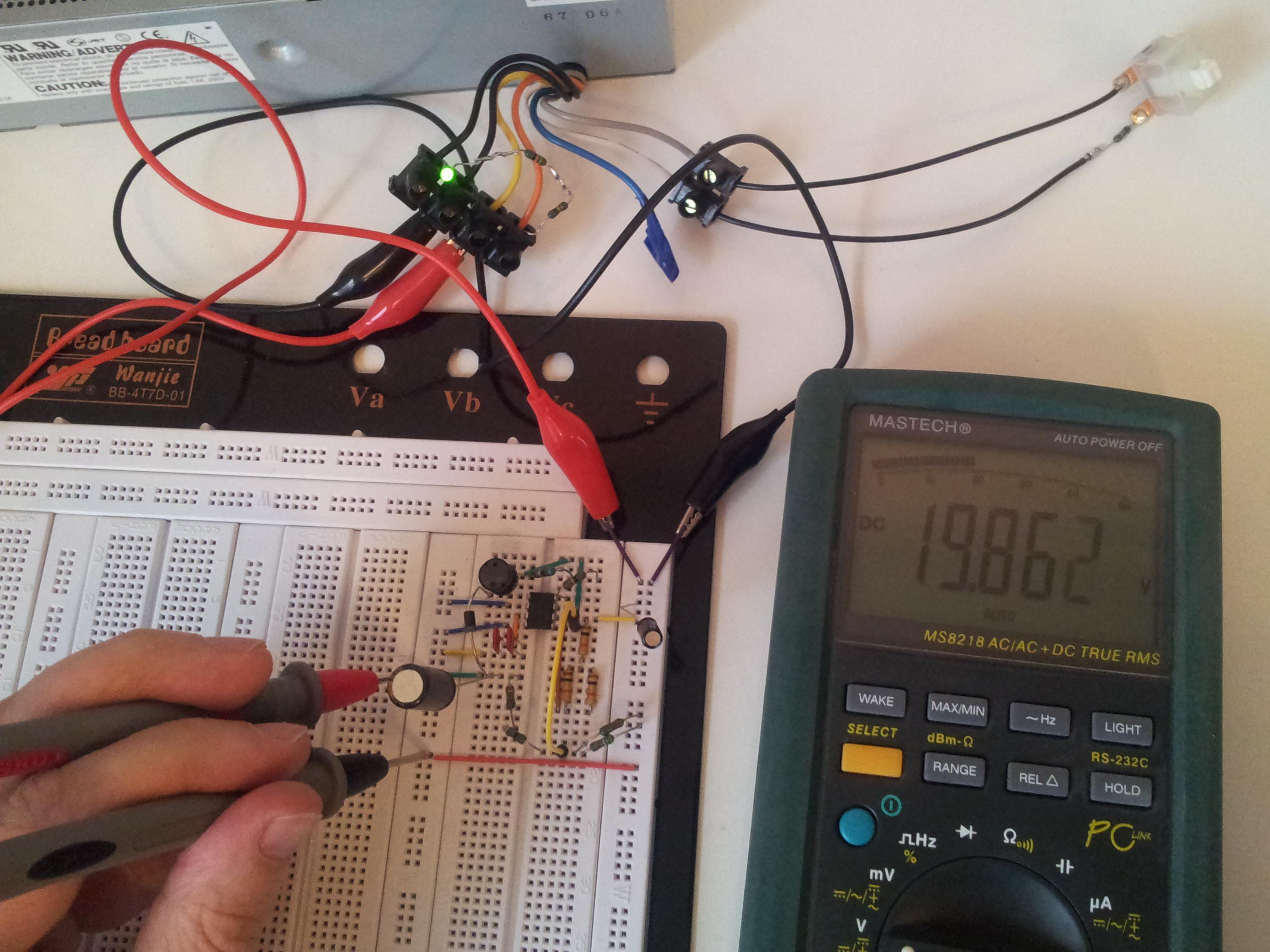
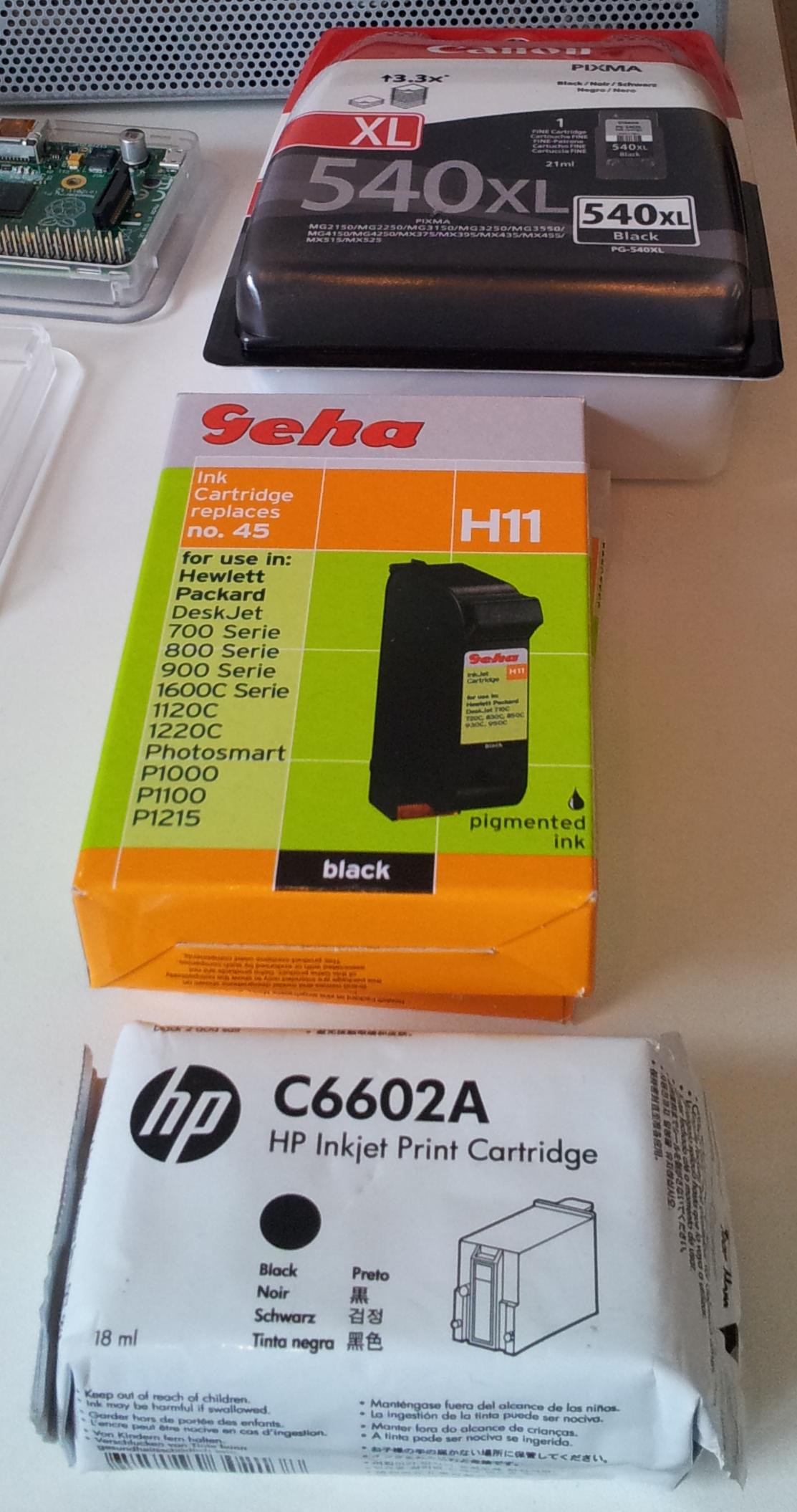
A Raspberry Pi is used as controller and later substituted by a more embedded solution (which is yet to be determined). The printhead is moved by a linear slide, which is harvested from an old CD-ROM drive. The Digital Stamp is initially powered by an ATX or similar power supply. A small selection of ink cartridges is there to be tested.

Overall goals:
- Small
- Easy to handle
- Wifi
- USB
- Local data storage
- Good printing speed & quality
- Real time clock or frequent time synchronization

Are you curious about something, do you found a mistake, or do you have questions? Please write a comment.

The system design document:

Licenses: For my own work (text and pictures) I use the

Creative Commons Attribution-NonCommercial-ShareAlike 4.0 International License

Creative Commons Attribution-NonCommercial-ShareAlike 4.0 International License

If you need another license, feel free to contact me.

Here's my concept video:

  • 1 × Raspberry Pi (Model B) Will later be substituted with some microcontroller.
  • 1 × Power Supply Unit - Voltek SPEC7188B Simple, ATX like, power supply. Final version shall work on accumulators.
  • 1 × Linear slide from old CD/DVD drive
  • 1 × ULN 2803A Darlington Array Drives the ink cartridge.
  • 1 × 74HCT4094 Shift register Serial in, parallel out, 8-bit.

View all 12 components

  • I'm on vacation

    Timo09/05/2014 at 20:28 0 comments

    I did not advance to the next round, so I've got time to go on vacation. ^^

    Work will continue later.

  • Raspberry Pi Connection

    Timo08/20/2014 at 14:15 0 comments

    I connected the RasPi with an old floppy IDE cable (cut at one end). It has 8 more pins than the Raspberry Pi, so these are ignored (would be cable ids 27-34).

    Here is the mapping of RasPi pins to floppy cable ids (only the first 26 of 34 can have a connection):

    Mapping as seen from the cable (7 pins have a cable connection, but aren't used on the board (the black ones)):

    Color coding:

    Black: Not connected

    Brown: Ground

    Red: 5V

    Orange: 3.3V

    Blue: Used GPIO Pins

    The two 5V pins are connected to the breadboards 5V lane, so it is powered through the board. The two 3.3V lanes are used in the 555 timer circuit from one project log ago. Three ground lanes are connected to the ground of the breadboard and two ground lanes aren't connected.

    GPIO25 (cable no. 5 between the black blocks) is used for triggering the 555. All other eleven GPIOs are connected to one port of an ULN2803A chip (the long chips in the top) each.

    For connectivity I'm using the LAN cable seen in the picture, later I will add a WiFi or Bluetooth dongle.

  • Prepare for Raspberry Pi interaction

    Timo08/20/2014 at 13:10 0 comments

    The Raspberry Pi can't guarantee the timing on its GPIO pins due to multi-tasking.
    So I need to assure a maximum on-time of the inkjet cartridge nozzles in hardware.
    I'm using a 555 in monostable mode for this task: SA555P from TI

    http://datasheet.octopart.com/SA555P-Texas-Instruments-datasheet-7285002.pdf


    One obstacle is the fact that a TRIG signal overrides a THRESH signal.
    Which means I need to shorten the pulse in order to shorten the pulse ...
    But there's hope: Using an RC-filter at the GPIO roughly shortens the pulse, for fine-tuning and sharp edge is the 555 responsible.

    Circuit diagram (calculations below):


    RC-trigger part (C1, R1, D1):
    D1 is a Zener diode of 3.6V protecting against overvoltage. The datasheet tells, that the trigger pin of the 555 gives max. 2µA at 0V. In order to trigger the 555 the voltage needs to stay below 1.1V, so let's say: The capacitor C1 must take at least 300ns (some time off the datasheet) to reach the level of 1V through resistor R1. To deal with 2µA, let's see that the maximal flow is much bigger than 2µA (= ignore this amount).

    Starting with some ballpark values:
    1mA maximal flow gives
    1mA  =>  3.3V / 1mA = 3300Ω =: R1

    Give it 300ns to rise up to 1V (buffer of 0.1V included):
    Uc = Umax * (1 - e^(-t / (R * C)))
    1V = 3.3V * (1 - e^(-300ns / (R1 * C1)))
    <=>   e^(-300ns / (R1 * C1)) = 1 - 1V / 3.3V
    <=>  -300ns / (R1 * C1) = ln(1 - 1V / 3.3V)
    <=>   C1 = -300ns / (R1 * ln(1 - 1V / 3.3V))
    So R1 = 3300Ω  =>  C1 = 251.82pF

    I got an R1 with 5617Ω which sets C1 = 147.94pF.
    My C1 got a measured capacity of 180pF.


    Capacitor C2 is just for stabilization. Most circuits I've seen used 10nF, I had 22nF lying around.


    Reset time: R2 + C3

    This gives some time till the chip has functionality, so it doesn't start with a peak at OUT.
    Again doing some ballpark calculations: Say 10µs as a start and charging with 1mA, so worst case RESET current is dealt with. The voltage level must be held below 0.3V in that time.

    Uc = Umax * (1 - e^(-t / (R * C)))
    0.3V = 5V * (1 - e^(-10µs / (R * C)))
    <=>   0.06 = 1 - e^(-10µs / (R * C))
    <=>  e^(-10µs / (R * C)) = 0.94
    <=>  -10µs / (R * C) = ln(0.94)
    <=>  R * C = -10µs / ln(0.94) = 0.0001616151s

    C := 10nF  =>  R = 16161.510712Ω
    C := 100nF  =>  R = 1616.1510712Ω

    Maximal flow:
    5V = R * 1mA  =>  R = 5kΩ
    =>  C = -t / ln(0.94) / 5kΩ
    C = t * 0.0032323 / Ω

    309.377µs per µF, thus using some µF capacitor.

    Result: Using R2 around 5.5kΩ and C1 with 22µF, but the exact values doesn't matter that much, just deactivating the chip for a few ms.


    Set the 555 pulsetime through R3 and C4:

    pulsetime = ln(3) * R3 * C4
    (Most circuit calculators use 1.1 instead of ln(3), because ln(3) = 1.09861228867.)

    I want a pulsetime of 5µs, so:
    5µs = ln(3) * R3 * C4
    Take a look at some test values:
    C4 := 10nF => R3 = 5µs / ln(3) / 10nF = 455.1196Ω
    5V = 455.1196Ω * I => I = 0.01098612A (while discharging)
    11mA is a bit too much for standby in my opinion.

    Since things are linear in this formula, let's divide it by 10.

    New try
    C4 := 1nF => R3 = 5µs / ln(3) / 1nF = 4551.196Ω
    5V = 4551.196Ω * I => I = 0.001098612A (while discharging)
    1.1mA is better and fine, because it is lower than the typical current consumption of the chip itself (3mA).

    I got R3 with 4570.4Ω and C4 with 1nF.

  • DC-DC Step-Up Converter

    Timo07/30/2014 at 19:35 0 comments

    I will need 20V for one of the ink cartridges (HP C6602A). So I need to step up my voltage from 12V to 20V. Here I use a step-up dc-dc converter around MC34063 (from UTC in this case).

    Multiple datasheets for MC34063 are available, e.g.:
    http://www.onsemi.com/pub/Collateral/MC34063A-D.PDF
    http://www.ti.com/lit/ds/symlink/mc33063a.pdf

    Even some in depth discussion:
    http://www.onsemi.com/pub_link/Collateral/AN920-D.PDF
    http://www.ti.com/lit/an/slva252b/slva252b.pdf

    Calculators and diagrams:
    http://dics.voicecontrol.ro/tutorials/mc34063/
    http://www.nomad.ee/micros/mc34063a/

    Video-tutorial by David L. Jones (funny and informative):
    http://www.eevblog.com/2010/09/10/eevblog-110-lets-design-a-dc-to-dc-switchmode-converter/

    Diagram with missing values (calculated below):


    Here are my calculating steps for the missing parts. The following parameters are chosen initially:
    Vin = 12V - 10% = 10.8V     (10% safety margin)
    Vout = 20V       (needed for one of the ink cartridges)
    Vf = 0.4V          (forward dropping voltage of diode by datasheet)
    Vsat = 0.5V      (switch saturation voltage by datasheet)
    f = 100kHz       (maximum frequency)
    Iout = 50mA     (starting low, have to see, what's really needed)

    Begin with calculations (just plug in values one-by-one):
    ton/toff = (Vout + Vf - Vin) / (Vin - Vsat) = 0.9320388
    ton+toff = 1/f = 10µs
    toff = (ton + toff) / (ton / toff + 1) = 5.17588µs
    ton = (ton + toff) - toff = 4.82412µs
    Ct = 4 * 10^(-5) * ton = 193pF         (used 2 * 82pF measured as 200pF)
    Ipk = 2 * Iout * (ton/toff + 1) = 0.1932A
    Rsc = 0.3 / Ipk = 1.55Ω                    (1Ω in series to 2 * 1Ω in parallel = 1.5Ω)
    Lmin = (Vin - Vsat) / Ipk * ton = 257µH           (used 330µH)

    Instead of choosing Vripple, I used a 470µF low ESR cap and therefore (this part of) the ripple is very low.
    Co = 9 * Iout * ton / Vripple          (used 470µF, so this part of the ripple is 4.6188mV)

    Vout = 1.25 * (1 + R2 / R1)
    => (Vout / 1.25 - 1) * R1 = R2
    here: 15 * R1 = R2

    From AN920-D.PDF (see links above): The current through R1 + R2 shall be 500µA.

    => R1 + R2 = 16 * R1 = 20V / 500µA
    => R1 = 2.5kΩ => R2 = 37.5kΩ

    I don't have those values, so I use (measured values):
    R1 = 2386Ω              (5473Ω and 4230Ω in parallel)
    R2 = 35820Ω            (976Ω and 34844Ω in series)
    R2 / R1 = 15.0126    (quite good value)

    The driver collector got 123.9Ω + 61.8Ω = 185.7Ω.

    The input filter capacitor is a 100µF/16V low ESR cap.

    Finished circuit:

    Measuring:

  • The parts have arrived

    Timo07/14/2014 at 12:58 0 comments

    My ordered parts arrived!

    Some ink cartridges with integrated print head:

    Shift register and Darlington Arrays:

    Switching regulators, Schottky diodes, low ESR electrolytic capacitors, inductors:

    Next thing to do: Making a concept video and then start building.

  • Added some details

    Timo07/09/2014 at 23:59 0 comments

    Ordered missing parts, set an initial goal for August.

View all 6 project logs

  • 1
    Step 1

    Order parts. Get spare time. ^^

View all instructions

Enjoy this project?

Share

Discussions

paul.tradeoptimize wrote 01/05/2022 at 07:03 point

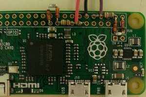
Thank you so much for this informative blog. I'll be in contact with <a href="https://www.cycjetcoder.com/inkjet-coding-machine/">Inkjet Coding Machine</a>

  Are you sure? yes | no

Samrath wrote 08/25/2014 at 07:21 point
Yes, I have wanted one of these for years. Since I was in school using a template to draw circuit symbols. I always imagined it having a screen to show your image transposed onto the paper so you could line things up properly, but that would probably increase the case size way too much. Great start

  Are you sure? yes | no

dandumit wrote 08/19/2014 at 11:51 point
could you please post some details about how to drive those print heads ? where do you apply signals ? what amplitude, what width ?

  Are you sure? yes | no

Timo wrote 08/24/2014 at 21:34 point
Hi, sorry for the late answer, but I had to meet a deadline. ;)
I got the timing for the HP C6602A covered in
https://hackaday.io/project/1745/log/8119-prepare-for-raspberry-pi-interaction
The voltage is generated with https://hackaday.io/project/1745/log/5925-dcdc-stepup-converter

  Are you sure? yes | no

Timo wrote 08/03/2014 at 14:06 point
Thank you for the link!

Looks similar to my idea, but I doubt it will work as expected, because their robot is driving around the paper and they aren't showing a live video of more than one (slow) line. They spend their video time emphasizing "design" and "small", but lack proof of well aligned lines. However they claim to print an A4 page in 40 seconds. We'll see.

Surprisingsly the very same ink cartridge (HP C6602A) is used. And it's planned to move on to a better cartridge as I do, too. But for now the print resolution is limited to 96x192 dpi.

I like their smart phone connectivity and universal printer interface. Maybe that's something to get inspired by. ;)
And last their design seems to be closed and set at a price point of 180 US$(?).

  Are you sure? yes | no

Mike Szczys wrote 07/16/2014 at 14:53 point
Cool concept!

Don't forget to document how this will be a "connected device" and to post a video that describes your concept and how you plan to follow the project through.

  Are you sure? yes | no

Blecky wrote 07/13/2014 at 16:51 point
Simple and functional idea. I like it!

  Are you sure? yes | no

Timo wrote 07/14/2014 at 12:49 point
Thank you!

  Are you sure? yes | no

Alex Nunn wrote 07/05/2014 at 20:44 point
This sounds pretty cool. What are you thinking for the method? An series of actuators that control the height of rubber/plastic blocks in a grid formation? Or perhaps an inkjet printer that can adapt to many surfaces? I'm curious to know.

  Are you sure? yes | no

Timo wrote 07/06/2014 at 00:41 point
Initially it will be an inkjet cartridge with integrated print head (e.g. from Hewlett-Packard) mounted on a linear slide for movement. More Details will follow as soon as I find more spare time. ^^ Thank you for your interest.

  Are you sure? yes | no

Similar Projects

Does this project spark your interest?

Become a member to follow this project and never miss any updates