 Matthew Kirk
A simple controller like mine can
be built for well under $20, including the enclosure! Now
no offense to Arduino; they make some great stuff, but I think even the
most loyal customers must agree that they charge a pretty hefty premium
for their products. But as long as you are willing to wait a while to
get the parts, some Arduino Pro Micros with usb hid support can be found
for as little as 7$ on Ebay. Make SURE to
order the ones with the newer ATMEGA32U4 chip, not the ATMEGA328 like
the pro mini which is cheaper, otherwise usb emulation will not work
without extra parts and more headaches.
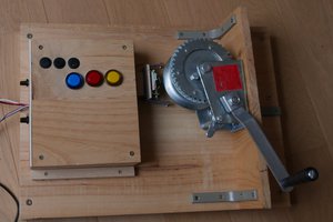
I wanted to make a controller with four buttons, which could then be expanded up to 12 presets by hitting more than one button at once. A nice led indicator would also be necessary to indicate what preset you are currently on. A resistor ladder was used to connect the buttons and free up pins. If you do create a resistor ladder, make sure to wire the buttons with different resistor values if you want to be able to distinguish multiple button presses at once. I used 220, 390, 680, and 2.2k ohm resistors to ensure adequate separation between the buttons and used a 1K resistor to tie the analog pin to ground. As with everything in programming, there are always 100 different ways to do the same thing, but I wanted something a little more elegant than just using digital writes to turn leds on and off. Seeing as I had nice clear colored leds, I figured a pwm cycled sine wave would provide a pleasing fading effect to the leds. To do this, I had the buttons switch boolean values on and off which then triggered the key presses and leds, otherwise the fading effect would stop as soon as you let go of the momentary switch. That's enough talking, lets see how it works shall we?
![]() The LEDs In ACTION!
The LEDs In ACTION!
![]()
I wanted to make a controller with four buttons, which could then be expanded up to 12 presets by hitting more than one button at once. A nice led indicator would also be necessary to indicate what preset you are currently on. A resistor ladder was used to connect the buttons and free up pins. If you do create a resistor ladder, make sure to wire the buttons with different resistor values if you want to be able to distinguish multiple button presses at once. I used 220, 390, 680, and 2.2k ohm resistors to ensure adequate separation between the buttons and used a 1K resistor to tie the analog pin to ground. As with everything in programming, there are always 100 different ways to do the same thing, but I wanted something a little more elegant than just using digital writes to turn leds on and off. Seeing as I had nice clear colored leds, I figured a pwm cycled sine wave would provide a pleasing fading effect to the leds. To do this, I had the buttons switch boolean values on and off which then triggered the key presses and leds, otherwise the fading effect would stop as soon as you let go of the momentary switch. That's enough talking, lets see how it works shall we?
 The LEDs In ACTION!
The Inside of the Box (Please Excuse the Point to Point Wiring!)
The Arduino Pro Micro![]()

The Momentary Switches
![]()

THE FULL SETUP!
The box was purchased at radio shack, and the leds/resistors/grommets were bought at Tayda Electronics. I recommend you use 1% resistors instead of 5%, or you may need to change the values in the matrix of my code slightly.
The box was purchased at radio shack, and the leds/resistors/grommets were bought at Tayda Electronics. I recommend you use 1% resistors instead of 5%, or you may need to change the values in the matrix of my code slightly.
VIDEO HERE:
 PixJuan
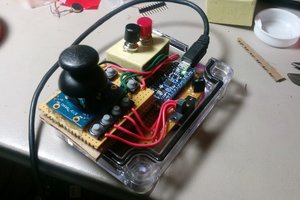
 Sinclair Gurny
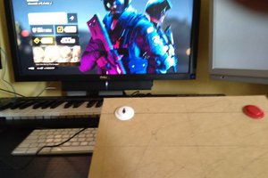
 Juan M. Casillas
 Zack
Zack