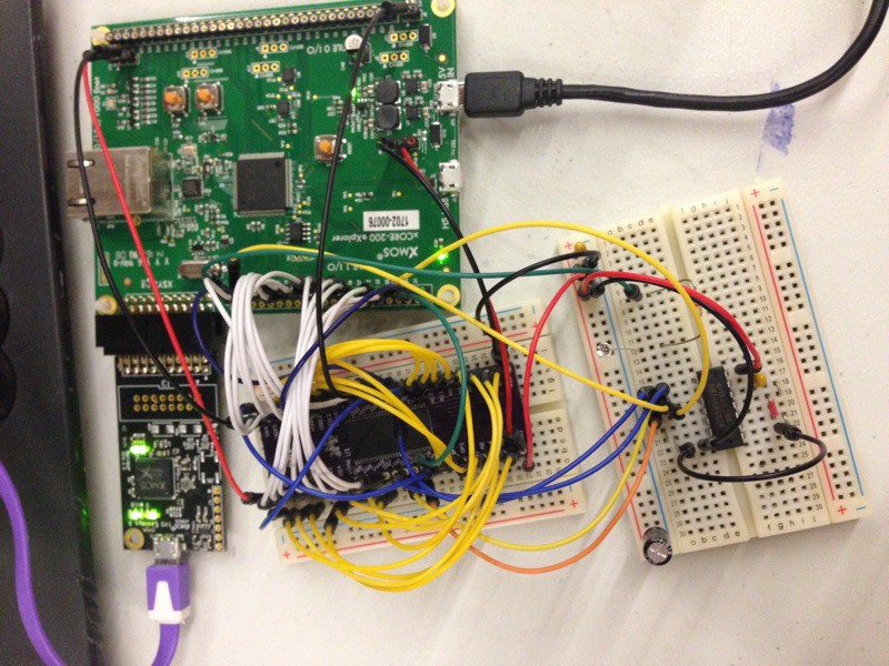
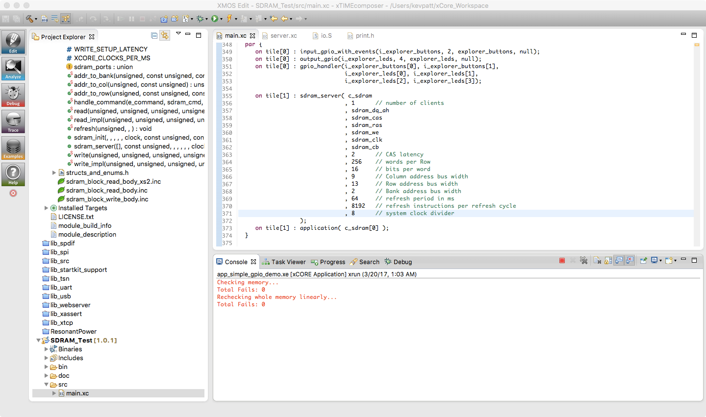
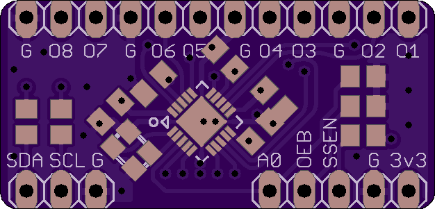
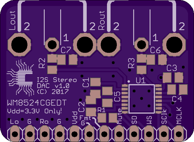
• I2S Stereo DAC now Available for Sale

    Kevin H. Patterson03/28/2017 at 19:09 0 comments

    The I2S Stereo DAC module is now available (pre-assembled) at Tindie.

  • Opus Port?

    Kevin H. Patterson03/27/2017 at 01:44 1 comment

    Thinking about porting the Opus audio decoder... YEA, or NAY?

    https://opus-codec.org

  • I2S Stereo Audio DAC Board Works!

    Kevin H. Patterson03/27/2017 at 01:41 0 comments

    The I2S Stereo Audio DAC board based on Cirrus Logic/Wolfson WM8524 has been tested and functions perfectly. Yay!

    I tested it using my XCORE-200 explorerKIT and the lib_i2s 2.3.0 library in "i2s_frame_master" mode. Currently I'm running it using the following parameters:

    • Master Clock: 12.288 MHz (generated externally by Si5351)
    • Word Clock: 48000 Hz
    • mclk_bclk_ratio: 4
    • mode: I2S_MODE_I2S

    Right now I'm just generating some nice sine waves at different frequencies, but the output looks (and sounds) very clean. Stereo separation is tested good as well.

  • Si5351 Clock Generator Library for XMOS

    Kevin H. Patterson03/27/2017 at 01:39 0 comments

    Ported the Si5351 clock generator library from Adafruit today, and made a nice xC interface for it that links up with XMOS' lib_i2c. I can program arbitrary frequencies on all 3 outputs over i2c from the xCore mpu, no problem. I will publish this on git very soon, after a clean it up a bit more.

    Right now I'm using the little 3-output board made by Adafruit, but I will be assembling one of my own 8-output boards soon to test as well. It should work fine with the existing code, and a few tweaks to enable outputs 4-8...

  • SDRAM Adapter Board Tested*

    Kevin H. Patterson03/20/2017 at 16:33 1 comment

    *YMMV

    Spent several hours testing the SDRAM adapter board. Haven't had a chance to play with the I2S stereo DAC yet.

    I did get the SDRAM to work with my XCORE-200 explorerKIT. However, it's definitely erratic. I'm able to write pseudorandom values to the entire 32 MB, and read them back successfully, but not 100% of the time, more like 90% of the time. My suspicion is that using a rats nest of jumper wires to a breadboard is not adequate with respect to the signal integrity required. But the library works, and I'm satisfied I know how to interface an SDRAM IC to the xCore.

    Here are my thoughts on the "reliability" issues. Please note that I'm not complaining about XMOS :). I realize the pictured setup is a completely hacked-up arrangement that is probably way out of spec, and it's probably a miracle I got it to work at all. :P The following thoughts are here just for anyone who is curious or might have some ideas of their own to share.

    Possible problems:

    1. Maybe there's a subtle timing or setup compatibility issue with the Micron SDRAM (I'm using part number MT48LC16M16A2TG-6A:G) See here. I don't have any ISSI parts, but I may order one and try it on another copy of the adapter board.
    2. As a result of reading the above thread, I ended up using the lib_sdram master branch from this git repo. It seems to be the most up-to-date. (I had trouble with the lib_sdram installed by xTIMEcomposer, but perhaps I gave up too soon?)
    3. I may have insufficient ground connections between the SDRAM adapter board and the explorerKIT. I need to populate the rest of the Tile I/O ground pads on the explorerKIT...
    4. All Vss connections on the adapter board are tied to a common ground plane, and all Vdd connections are tied to a common 3v3 rail. The SDRAM is decoupled by two 0.1µF and two 1µF MLCC X7R caps on the adapter board. Maybe this is not enough.
    5. Noise picked up by the jumper wires, or signal issues caused by inductance, excess capacitance, lack of impedance control on these lines, or the breadboard stubs. I need to check this on my scope. Perhaps I have bad skew, reflections, ringing, and/or overshoot...
    6. I don't have an ultra-fast NOR gate handy, so I'm using a 74AHC02. It's rated about 6ns at 3v3, compared to the 2ns of the 74LVC02 part recommended by XMOS, so about 1/3 the speed. This alone could be the source of all my problems, but I would think it would become irrelevant at slower clock dividers... But I'll order an LVC part and try.

    Oddly enough, I get pretty good results at certain clock dividers. I can run the pictured setup at div=8 (31.5 MHz), but no faster. HOWEVER, going slower (div=9, 10, etc.) doesn't seem to help! I even tried running at div=20 and 25, but everything slower is about 10-20% "reliable", compared to about 90% at div=8. I tried changing CAS to various numbers, no help. 2 works best at div=8, and 3 is marginally better at slower clocks... I also messed with "#define N (1)" in io.S, but changing it to 0 makes things almost totally unusable, even at very slow clocks (div=20, etc.).

    Perhaps the most nagging issue is that I feel like I should be able to get this to work reliably at a slower speed (say 5 or 10 MHz). Perhaps there are some tweaks that I need to make to the library that I'm not aware of?

    So, barring some miraculous insight that I'm yet to have, I'll probably end up designing a new (4-layer) board that incorporates both the SDRAM IC and an XMOS mcu on the same board, with impedance controlled traces, etc. Definitely a learning experience.

  • I2S Stereo DAC and SDRAM boards assembled

    Kevin H. Patterson03/18/2017 at 00:00 1 comment

    I've assembled the first copy of the I2S Stereo DAC and TSOP54 SDRAM Adapter boards. I plan to test them this weekend.

  • 8-Channel Clock Generator Board Designed

    Kevin H. Patterson03/10/2017 at 05:10 1 comment

    Got the clock generator board designed and ordered. This board is based on Silicon Labs Si5351A-B-GM, which can generate up to 8 independent channels of non-integer-related clock signals between 8 kHz and 160 MHz. They share a common clock domain too, so no relative drift between channels.

    I plan to use this board to generate a variety of different clocks for the Anacon-xC project. This includes DAC pixel clock, I2S audio master clock and bit clock, NTSC/PAL encoder 4FSC clock, and in the future maybe even the XS-200 core clock as well (prob. 24 MHz).

    For an example of how this would work: The xCore chip would send out a desired pixel clock frequency over I2C. The Si5351 would output this clock to both the video DAC and a 1-bit input on the xCore mcu. Falling edge of the clock would trigger the xCore to output 24-bit RGB data on a buffered port (using that input pin for clock), and the DAC would load the data on the rising edge. This makes it easy to select use any arbitrary pixel clock frequency, and take full advantage of xCore port buffering. Right now I'm burning a fair number of CPU cycles in the pixel output loop just doing the fractional division of the block clock to get an approximate desired pixel clock. Using an external clock allows us to program in a more "event driven" mode, where the external clock is an event, rather than generating all these events ourselves in code. Timers and port timestamps help a LOT, but when the clock frequencies are very high even a little overhead starts to add up.

    The board includes all necessary support circuitry including the required crystal (25 or 27 MHz). All programming is done over I2C. Adafruit has an Arduino library for the 3-channel version of this chip which I can probably modify. Silicon Labs also has a little Windows app that can generate the right register values based on your choice of desired frequencies.

    Board format is wide DIP style, and should fit nicely on a solderless breadboard. Although I only used 2 layers in the design, I took some care to route signals and power in a sane manner considering the potential frequencies involved.

    Eagle 7.5 files for this board are available in the project files section.

    PCB on OSH Park

  • 8-Channel PLL Clock Generator

    Kevin H. Patterson03/09/2017 at 07:26 0 comments

    Almost done designing an 8-channel clock generator based on Silicon Labs Si5351A-B-GM. This board will be in a wide DIP form that can plug into a solderless breadboard. Control is via I2C, and up to 8 independently programmable frequencies from 8 kHz to 160 MHz can be generated. (PLL is driven by an on-board crystal.)

  • Stereo Audio DAC Board Designed

    Kevin H. Patterson03/09/2017 at 07:22 1 comment

    Got a mini adapter board designed and ordered for the Cirrus Logic WM8524CGEDT I2S Stereo Audio DAC. 24-bit, 106dB SNR. Dual RCA line-level outputs, which are also available on the pin header.

    BTW, this DAC runs directly on a single 3v3 supply. It has a built-in charge pump and bias servo to output true 2V line-level signals without using external coupling capacitors. This also eliminates the "pops" commonly encountered when these devices are powered on or off. Cool! :)

    Eagle 7.5 files for this audio DAC board are available in the project files section.

    PCB on OSH Park

  • SDRAM Breakout Board Designed

    Kevin H. Patterson03/06/2017 at 04:31 0 comments

    Got an SDRAM breakout board ordered with OSH park today, so at some point I'll try out the SDRAM library (on XS-2, likely). I have an MT48LC16M16A2TG-6A:GTR (256 mbit, 16 bit ifx) to put on it. The "header" holes in this PCB are large because they are designed to allow "deep seating" of special machined socket strips with long pins that extend through the PCB. This allows the PCB to be plugged into a solderless breadboard as well as exposing a set of pin sockets on the top for connecting extra leads or components, allowing it to be used without the breadboard if desired. I'm using Mill-Max part number 311-93-164-41-001000.

    Eagle 7.5 files for this breakout board are available in the project files section.

    PCB on OSH Park