 andrew
This project was born from a real world need to send data from my rooftop solar PV system back to my home server so I could keep a track of how the system was performing. Datalogging the output on a minute by minute basis was easy enough, however, I wanted something that could take a snapshot of the output from the system just once a day. The system is powered from the solar PV string it is monitoring. A Mornsun Switchmode power supply down regulates the DC supply voltage to just 5 Volts which is perfect for powering the Arduino and GSM module. Testing has shown this component is about 87% efficient. An alternative system I have tried used a second micro controller to create an MPPT device from a separate 12V 2W solar panel, however, adding a new solar panel to the system presented more challenges including how to mount it to the roof etc. (As Dave Jones would say... "Arghhh Too Hard")
To keep things simple, I elected to use the Mornsun PV10-27B05 Switch Mode power supply which is rated to work between 200-1200 V DC. In practice, I found that it started working at 165 V. The 5 V output doesn't require further filtering. I have also tried the Mornsun LD02-10B05 Switch Mode power supply which operates at the lower range of 85-305 V. This unit was excellent for monitoring smaller systems (i.e. Thin film mono panels where the voltage is lower and the current higher)
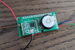
The 5 V is then used to supply the daughter board (designed in Eagle) and the Arduino stack. Voltage from the DC input is measured using a simple voltage divider (with a decoupling capacitor). Current is measured using an Allegro ACS758 sensor. Both of the outputs from these two modalities are fed into the ADC on the Arduino. I have also taped an LM335 temperature sensor to the underside of the closest panel. This sensor was included to give some feedback on the panel performance when the Australian temperatures in Summer reach their scorching peaks, but for the most part, this information serves little purpose in winter.
The ADC in the Arduino converts the data into real numbers and then outputs the values and a time stamp (from a Real Time Clock) to the SIM900 GSM module. The GSM module then sends the data to a second GSM enabled Arduino on my office desk.
The SMS is perfect for tracking large numbers of solar PV installations especially in residential areas where the clients can't track the panel/inverter output themselves. Sometimes the inverter is mounted too high on the wall for the older resident to see the LCD display. For example, Retirement villages.
Sometimes, consumers don't even think about their PV installation - out of sight, out of mind. It is useful for those who only want to be notified when there is a problem and it forms a kind of insurance policy to ensure the correct functionality of their installation is being maintained.
I have drawn my daughter board in EAGLE and etched out my own single sided through hole board using Ammonium Persulfate. My next iteration will include the ATmega328 on the daughter board, with the RTC. I would love to tackle surface mounted components too but I need to save up for a reflow oven and controller first.

 strange.rand
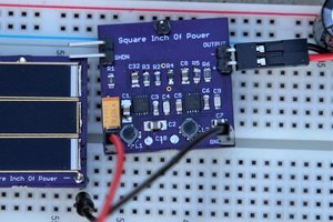
 OzQube
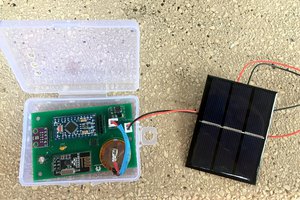
 Gos
Gos
 Abid Jamal
any updates to this project?