 SirClover
This is the system design.
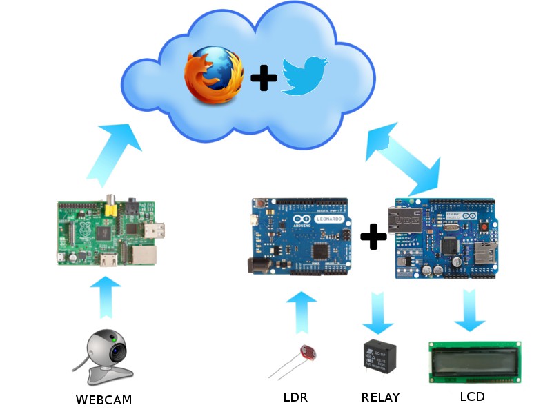
As you can see, in the side of Arduino, it has connected the LDR to measure the light; the relays, to activate the exits to lights, blinds, ... and the LCD to write the messages of the state of the PCB.
In the side of the Raspberry Pi it has connected the webcam to see what's happening in home.
This is the video where is explained the system design.
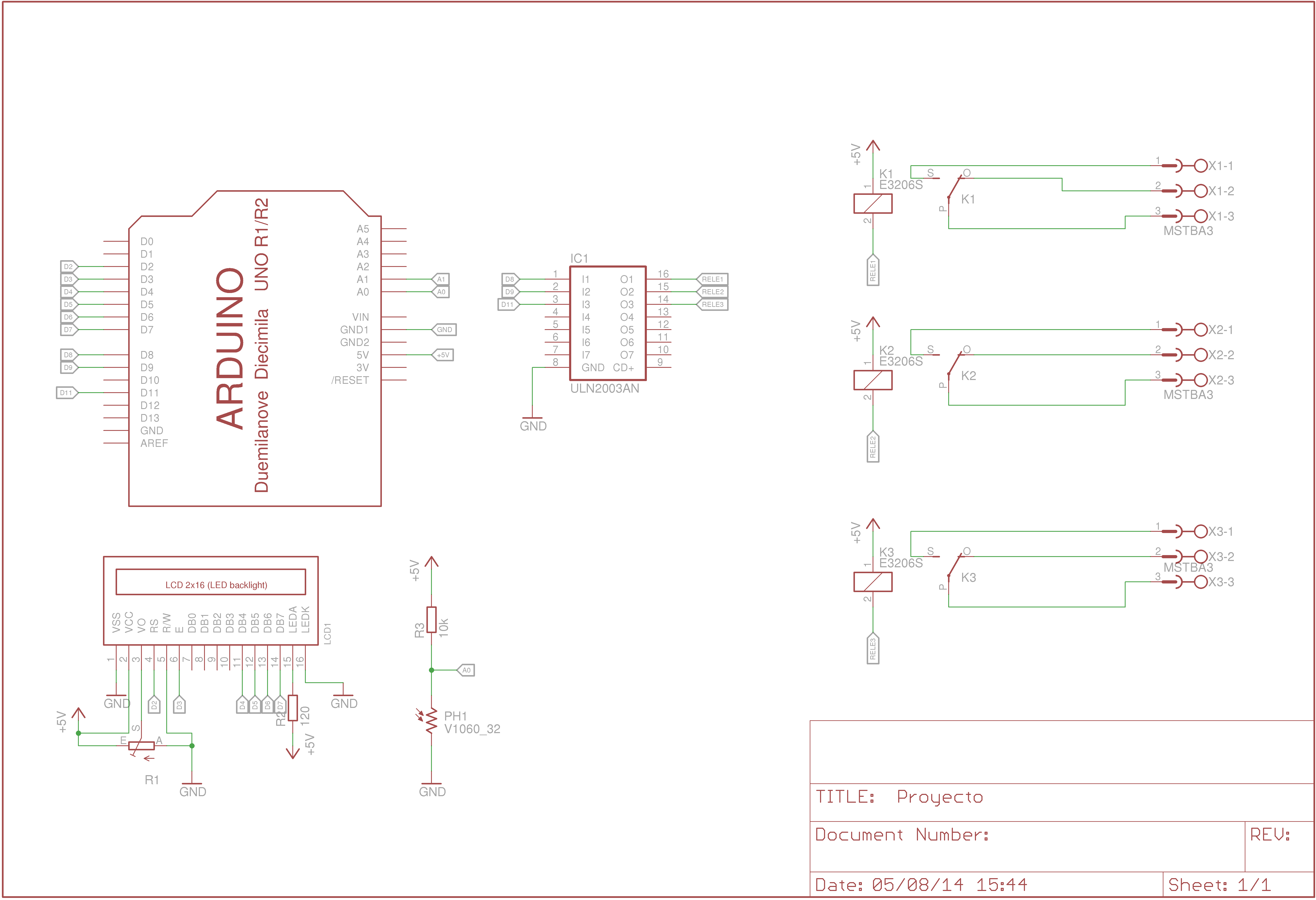
This is the .sch archive of the project.

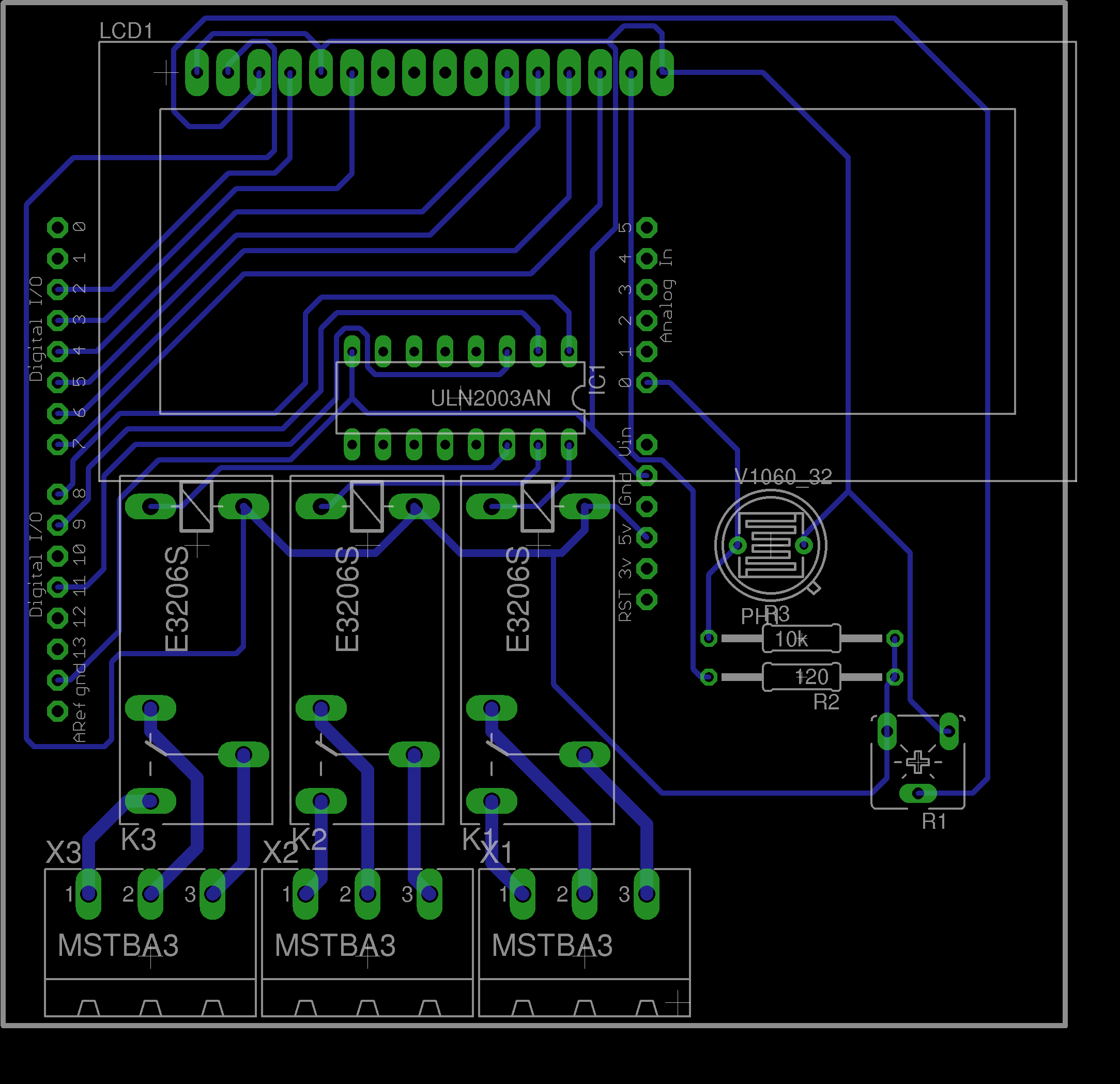
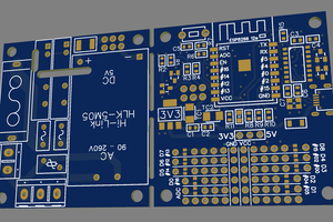
This is the pcb.

The video of the full demonstration of the project.
The program presents a problem because it can't post two tweets equal. It post one time "Blinds UP", but if you clic another time it later, it can't post it.

 Subhajit
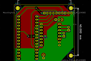
 adria.junyent-ferre
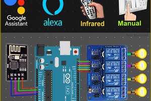
 David BC