Close
0%
0%

RV Rooftop A/C MPU Replacement

This project chronicles the successes, and frustrations to defeating the securities put in place by RV appliance manufacturers.

Similar projects worth following

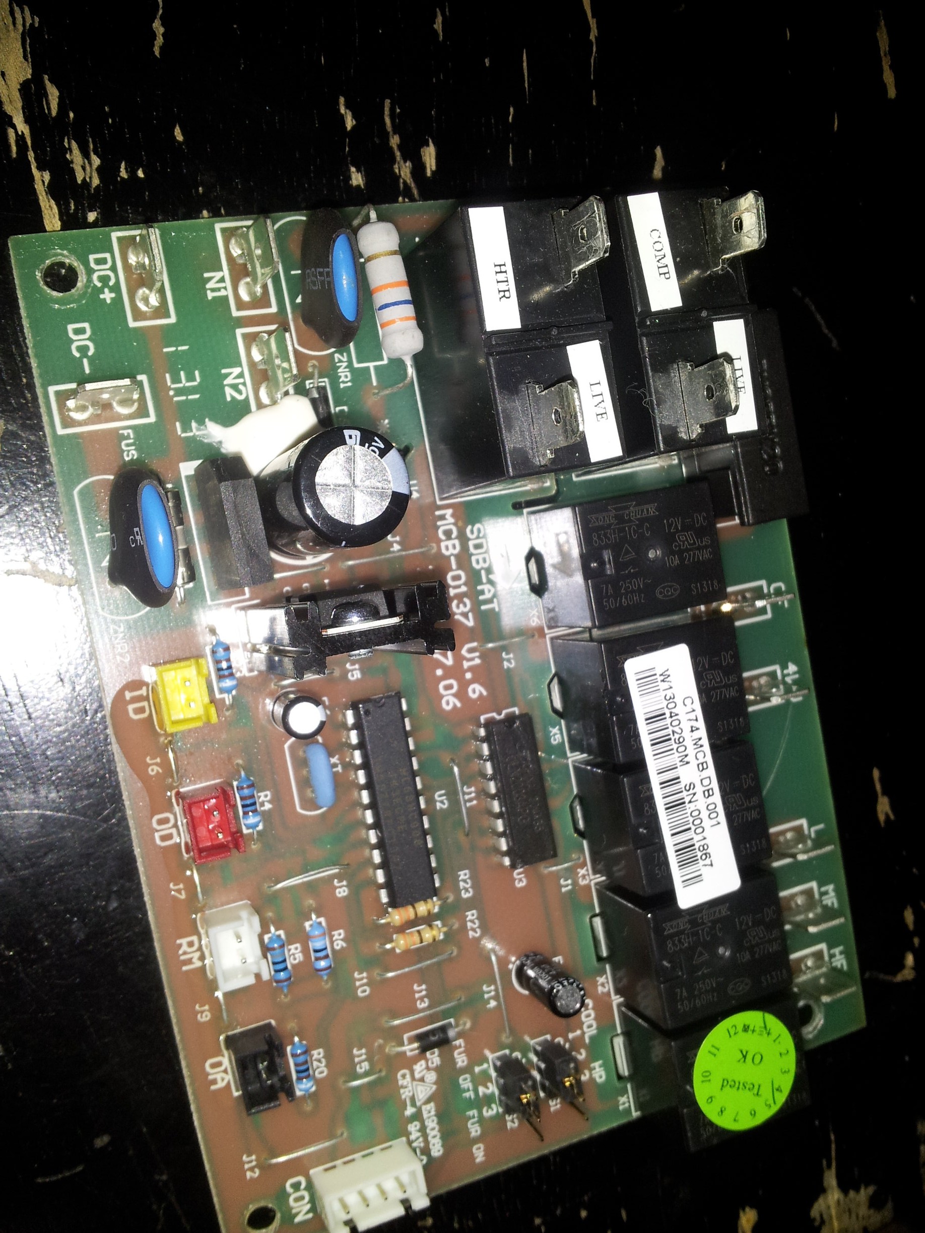
Original board removed from A/C. CON on far right of picture is the control box connection. ID, OD, RM, and OA are temperature sensor inputs either inline with it's respective coil (ID & OD) or air temp (RM & OA). Fur OFF/Fur ON and COOL/HP are option settings. Fur OFF/Fur ON is an option to control and electric furnace addon, and COOL/HP is an option for heat pump capable units (of which mine is not).

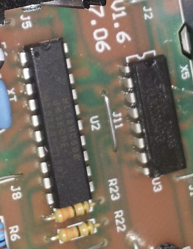
The MCU (Lower chip) is a Motorola MC68HC908 8-bit MCU. Top chip is a ULN2003APG Darlington driver array. The Darlington array drives the relays. The MCU commands the Darlington array.

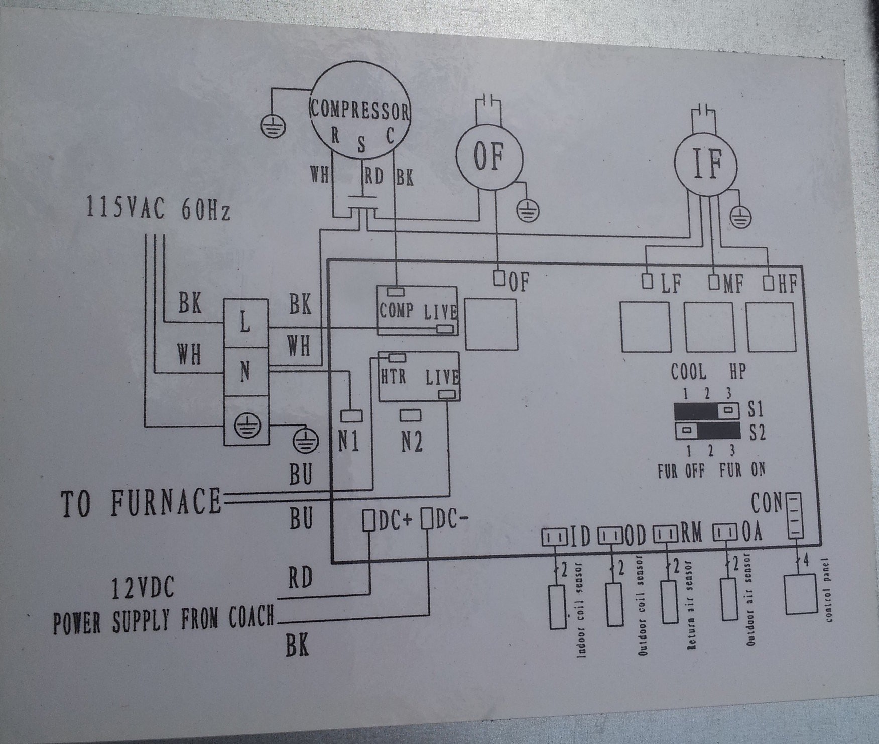
Here is the wiring diagram of the system conveniently located on the inside of the access panel...

And you thought I did all of that detective work on my own! For shame!

  • 1 × Sparkfun Pro Micro 5v/ 16MHz
  • 1 × Atwood Air Command 15,000BTU Rooftop A/C (Top unit only) I'm sure you can use others. This is just what we decided on.
  • 3 × Feet .5mm ridgid copper wire (coated or uncoated) This is to form a riser and allow pin rewiring. Since the M/C on the board does not match the pinout of the Pro Micro.
  • 1 × 12v 500mA power supply
  • 3 × 1.8KΩ Resistor

View all 7 components

  • A note about temperature sensors and calibration

    Daniel Roseman08/26/2014 at 12:26 0 comments

    So, just to address the niceties of the temperature inputs. I honestly did not have to do much except realize that the numbers were related. This is to say, the numbers for three of the four inputs (Room Air, Outdoor Coil, Outdoor Air) are input/10 = Celsius. The last (Indoor Coil) is input/10 = Fahrenheit. This is how the factory designed it. This helped rapid prototyping quite a bit as I didn't have to do any calibration. The reason for Indoor Coil being different from all of the others is because it runs below 0 Celsius. The Celsius temp probes would not be able to sense anything below (or close to) 0. So, they calibrated the Indoor Coil for Fahrenheit.

  • This one's a dry read...

    Daniel Roseman08/16/2014 at 17:49 0 comments

    So here is the code, and since Hackaday.io doesn't support the code html flag, I will just give it alot of space before I start it and after. I will also eventually share this code on github as well. All of the regular gnu rules still apply. Keep my name on in and if you repost it give me cred. Otherwise enjoy! Oh, and if you have suggestions feel free to drop me a line. I am very approachable like that! ;)

    /*
    Atwood RV Air Conditioner Controller

    This program is designed for an Arduino ProMicro 5V/16MHz from sparkfun.com

    software designed, built, and hardware modified by Daniel Roseman 2014 August 13th
    */

    #include <EEPROM.h>
    #include <avr/wdt.h>


    // Defining Variables
    int of = 4; //Outdoor Fan Command pin = 4
    int heat = 5; //Heat command pin = 5 (PWM)
    int comp = 7; //Compressor command pin = 7
    int ifa = 8; //Indoor Fan A command pin = 8
    int ifb = 9; //Indoor Fan B command pin = 9
    int id = A0; //Indoor Coil Analog Input pin = A0
    int od = A1; //Outdoor Coil Analog Input pin = A1
    int rm = A2; //Room Air Analog Input pin = A2
    int oa = A3; //Outdoor Air Analog Input pin = A3
    int cool = 14; //12v Cooling command from RV controller
    int lfan = 15; //12v Low Fan command from RV controller
    int hfan = 16; //12v High Fan command from RV controller

    // This setup routine runs once anytime the device starts from scratch
    void setup() {
    wdt_reset(); //reset watchdog
    Serial.begin(300); // open the serial port at 300 bps:
    pinMode(of, OUTPUT); // Outside Fan
    pinMode(heat, OUTPUT); // Electric Heater
    pinMode(comp, OUTPUT); // Compressor
    pinMode(ifa, OUTPUT); // Inside Fan Output A
    pinMode(ifb, OUTPUT); // Inside Fan Output B
    pinMode(id, INPUT); // Indoor Coil Sensor
    pinMode(od, INPUT); // Outdoor Coil Sensor
    pinMode(rm, INPUT); // Return (Room) Air Sensor
    pinMode(oa, INPUT); // Outdoor Air Sensor
    pinMode(cool, INPUT); // Cool Call Input
    pinMode(lfan, INPUT); // Low Fan Call Input
    pinMode(hfan, INPUT); // High Fan Call Input
    wdt_enable(WDTO_2S); //Enable watchdog for 2 second delay
    if(analogRead(od) > 560){
    powerfailSafety();//If outdoor coil temp is above 56c then the outside coil is VERY hot and the compressor "may" have been operating not too long ago. Call powerfailSafety().
    }
    if(EEPROM.read(1) == 1){
    powerfailSafety2(); //If EEPROM address 1 reads "1" on power up then most likely the power failed while compressor was operating. Call powerfailSafety2().
    }
    }

    //Start of Main Loop
    void loop() {
    wdt_reset(); //reset watchdog
    if(analogRead(od) > 795){
    hightempSafety(); //If outdoor coil goes above 79.5c, call hightempSafety().
    }
    if(analogRead(rm) < 150 || analogRead(id) < 200){
    freezeSafety(); //If room air temp goes below 15c or indoor coil temp goes below 20F, the call freezeSafety().
    }
    delay(1000); //delay 1 second
    wdt_reset(); //reset watchdog
    Serial.print("Indoor Coil = ");
    Serial.print(analogRead(id) / 10);
    Serial.print("F");
    Serial.print("\t");
    Serial.print("Outdoor Coil = ");
    Serial.print(analogRead(od) / 10);
    Serial.print("C");
    Serial.print("\t");
    Serial.print("Intake Air Temp = ");
    Serial.print(analogRead(rm) / 10);
    Serial.print("C");
    Serial.print("\t");
    Serial.print("Outdoor Air Temp = ");
    Serial.print(analogRead(oa) / 10);
    Serial.print("C");
    Serial.print("\t");
    Serial.print("Compressor Call = ");
    Serial.print(digitalRead(cool));
    Serial.print("\t");
    Serial.print("Fan Call Low = ");
    Serial.print(digitalRead(lfan));
    Serial.print("\t");
    Serial.print("Fan Call High = ");
    Serial.print(digitalRead(hfan));
    Serial.print("\t");
    Serial.println(" ");

    if(digitalRead(cool) == LOW && digitalRead(lfan) == LOW && digitalRead(hfan) == LOW){
    digitalWrite(of,LOW);
    digitalWrite(comp,LOW);
    digitalWrite(ifa,LOW);
    digitalWrite(ifb,LOW);
    if(EEPROM.read(1) == 1){
    EEPROM.write(1, 0);
    compressorLockout();
    }
    }
    if(digitalRead(cool) == HIGH && digitalRead(lfan) == HIGH && digitalRead(hfan) == LOW) {
    digitalWrite(of,HIGH);
    digitalWrite(comp,HIGH);
    digitalWrite(ifa,LOW);
    digitalWrite(ifb,HIGH);
    if(EEPROM.read(1) == 0){
    EEPROM.write(1, 1);
    }
    }
    if(digitalRead(cool) == HIGH && digitalRead(lfan)...

    Read more »

  • Nose to the Grindstone...

    Daniel Roseman08/13/2014 at 13:38 0 comments

    So, I decided on an arduino platform. For my requirements I needed a couple of things:

    First, I needed the ability to measure at least 4 analog values from 0 to 5v.

    Second, I needed at least 1 PWM output (for the future electric heater).

    Third, I needed at least 3 normal inputs (ie: off, on).

    Fourth, I needed one normal output for a heartbeat/status light. And four normal outputs for inside fan high/low, outside fan on, and compressor on.

    Fifth, I needed a couple of data lines for future communications.

    Sixth, It had to have a watchdog as well as enough memory to hold the many future upgrades planned for it.

    Whew! That's a huge list!

    Well, after much ado I decided on the Sparkfun ProMicro 5v 16MHz. I could have bought one of those Chinese knock-offs for a lot cheaper, but this thing needed to be rock solid. It fit into the case without too much fuss, and is well designed.

    Now to put my nose to the grindstone and get to wiring and coding...

  • Decisions... decisions...

    Daniel Roseman08/06/2014 at 16:14 0 comments

    So, a little primer on the Motorola MCU on this main board. This is an 8-bit 8MHz 5v MCU with 4kb Flash designed by Motorola and built by Freescale Semiconductors. Four of it's input pins are 8-bit A/D converters and has 12 GPIO pins overall. This is a great MCU for professionals and tinkerers alike, as long as you have the proper hardware to program it in the first place.

    More important to me in this dive down the rabbit hole, is that it has a security register. Once set, the end user CANNOT read flash contents without wiping it first... Meaning you can reset the MCU to zero but you cannot modify the original code. Since I don't have the equipment to identify whether or not that register had been set, I must assume it had been.

    So, I have two options. Buy more equipment that we really can't afford in order to learn then hopefully reprogram an MCU. Or spend a fraction of that investment on a ready-to-program arduino...

    Decisions... decisions...

  • And so it begins...

    Daniel Roseman08/06/2014 at 12:43 0 comments

    Once we recieved and unwraped the A/C we realized that it required a control box that is sold seperately for more than $150. On closer inspection, the control box connects to the A/C via a four wire connection. 5v and Ground is supplied by the A/C main board and talks via a balanced (two wire) data connection. I didn't try to discover the protocol as our existing onboard control box communicated via dedicated signal lines at 12v. Three to be exact. 12v compressor command, 12v low fan, and 12v high fan. Also I have limited electronics toolset (which does not include an o-scope).

    Now I have a problem. Upgrade our entire control system at a huge expense (we are poor BTW), get a different A/C unit at a huge expense (did I forget to mention we are pretty poor...), or I can get to hacking...

    Well, the logical choice for me was hack the crap out of it...

    And so it begins...

  • Choosing an A/C...

    Daniel Roseman08/06/2014 at 12:31 0 comments

    Honestly, I did not realize that I would be starting this endeavor when we first set out to replace one of the two A/C units in our 32' RV. We (me and my wife) thought this would be as easy as changing a window unit... No big deal.

    We decided that an Atwood Air Command 15,000 BTU unit was a good choice due to the handling capacity and price (we found this unit online at an RV salvage dealer for $200). Regular unit price hovers around $650 for the unit itself (not including supporting hardware and electronics).

View all 6 project logs

Enjoy this project?

Share

Discussions

Similar Projects

Does this project spark your interest?

Become a member to follow this project and never miss any updates