 tshen2
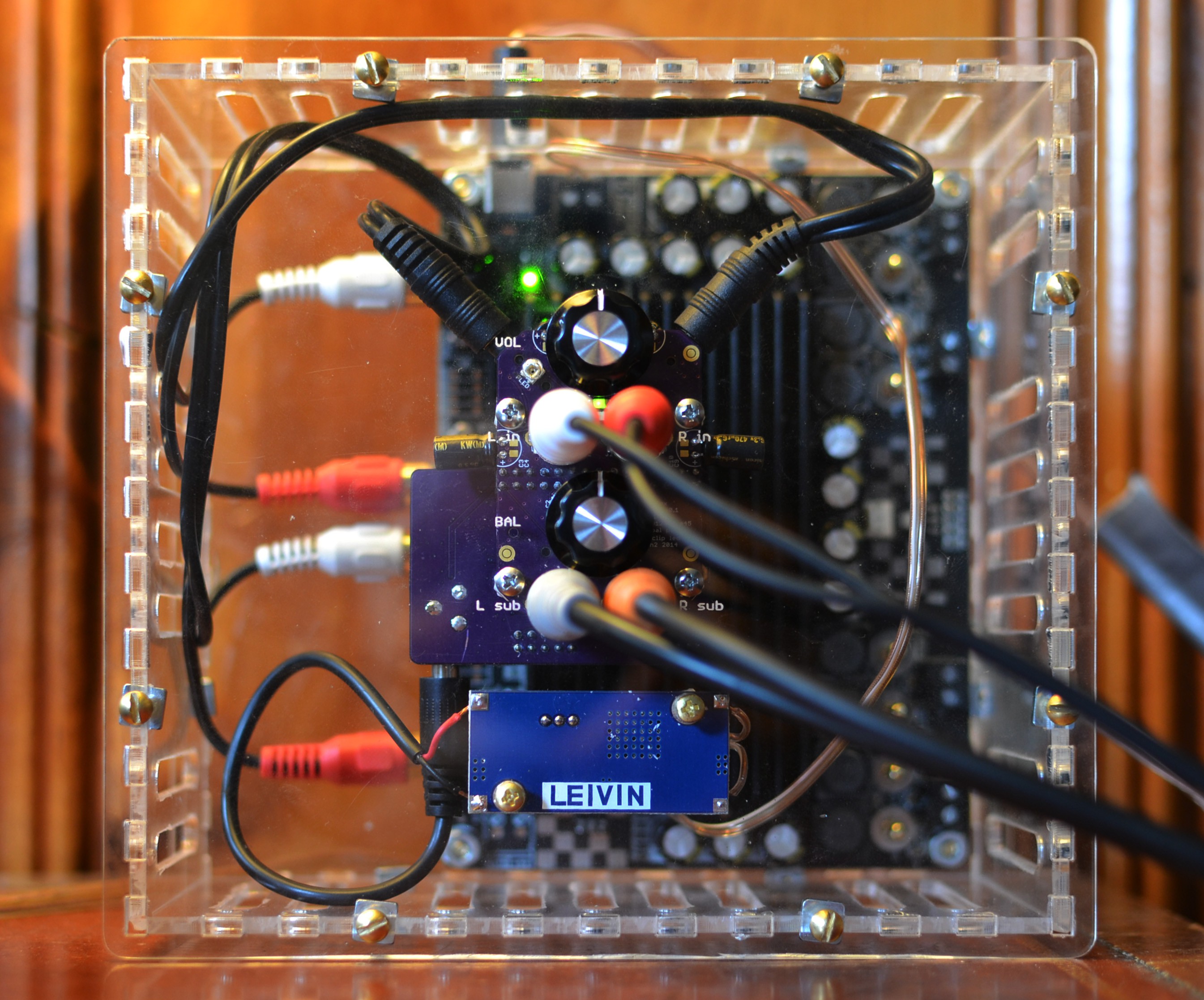
i appear to have a DSP. time to set it up!
first, the basics:
- do the two inputs (ADCs) work?
- do all six outputs (DACs) work?
- do my knobs and clip-indicator lights work?
- does it self-boot off of EEPROM?
here's the architecture again:
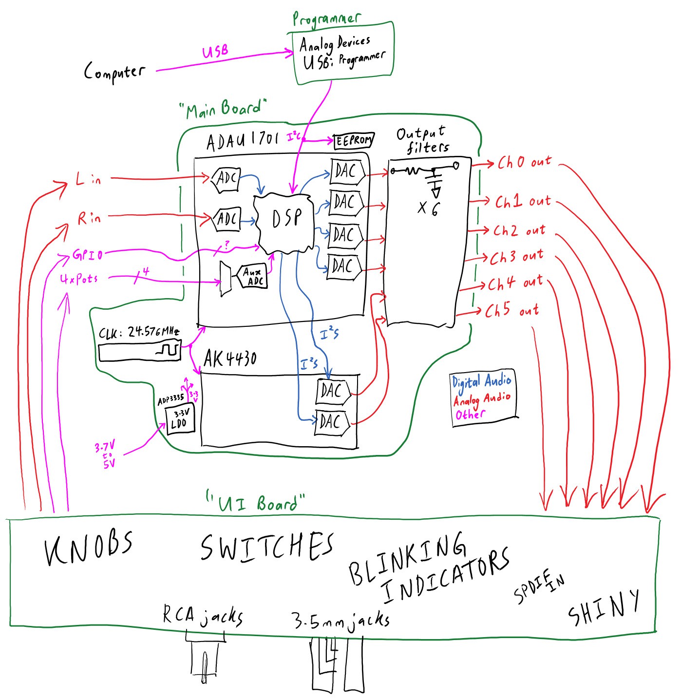
(DSP architecture, version 2 - final)
as you can see, both ADCs and four DACs are built into the ADAU1701 itself. they communicate directly with the DSP core using internal Analog Devices magic. setting them up is easy!
the two DACs in the AK4430 are more troublesome. they are supposed to receive digital audio through stereo I2S. i have zero prior I2S experience, so this is a bit of a bumble-thon.
I2S seems to need these signals:
- bit clock. (BCLK) for clocking the arrival of data bits.
- serial data line. (SDATA_IN) for.. data.
- left-right clock. (LRCLK) this indicates if your data goes to the left or right channel.
the AK4430 also wants the 24.576MHz master clock so it can jostle its switch-cap filter, as mentioned in part 2. the master clock can be wired right in. but how do we generate the other signals?
the ADAU1701 datasheet has the answer on page 46:
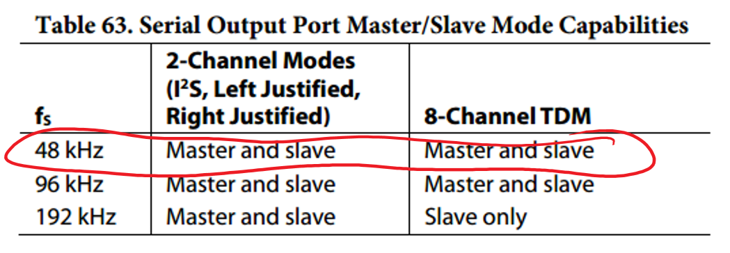
(at 48kHz sample rate, the ADAU1701 can be the I2S master.)
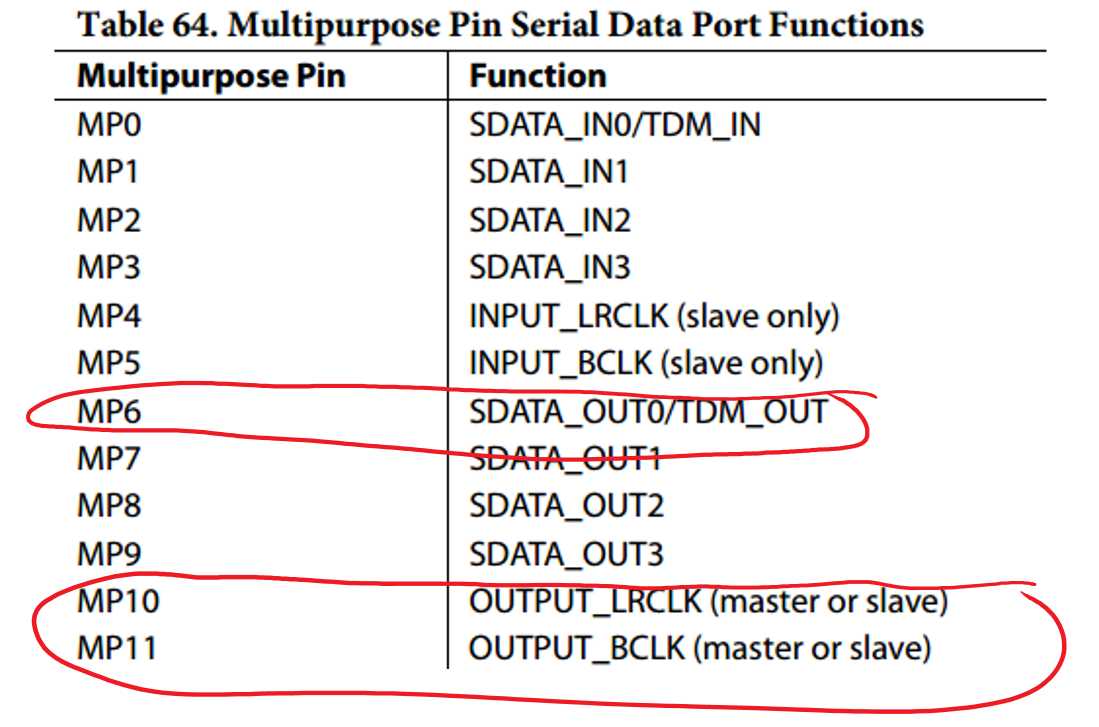
(the general-purpose IO pins, MP6, MP10 and MP11 can be our I2S bus)
all DSP programming is done through the SigmaStudio software from Analog Devices. it is a beautiful example of flow-based programming, which is a great way to think about signal processing chains.
so let's set up the I2S bus!
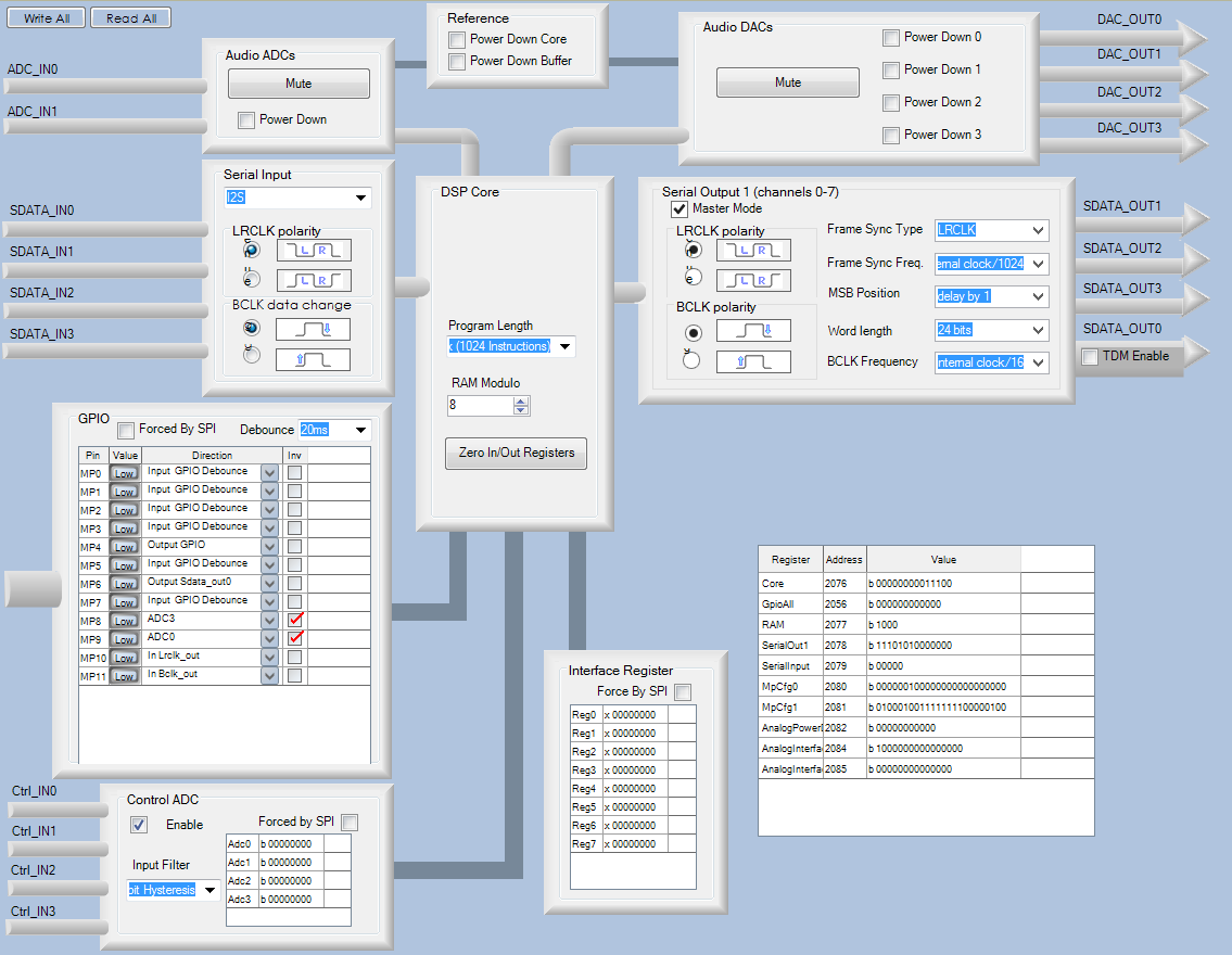
(that 'Serial Output 1' box contains everything we need to know)
why is the left-right clock (aka 'Frame Sync' clock, aka 'LRCLK') set to 'internal clock/512' = 48kHz? well, 48kHz is our sample rate. at every sample, we have to first send some right-channel data (with LRclock low) and then some left-channel data (with LRCLK high). that means, repeating at 48kHz, LRclock must spend some time low and some time high. so that is a 48kHz square wave!
and why the bit clock (aka 'BCLK') set to 'internal clock/8' = 3.072MHz? well, it's transmitting stereo 24-bit audio. that means it has to transfer two 24-bit integers (at least 48 BCLK cycles!) for every audio sample. let's allocate 64 BCLK cycles per audio sample. if a clock is 64 times faster than our sample rate (48kHz), that's 3.072MHz.
UPDATE: for some strange reason, in order to get the 48kHz sample rate, you need to set 'Frame Sync' frequency to 'internal clock/1024' and BCLK to 'internal clock/16'. it doesn't make sense, but that's what works. The image above has been changed accordingly.
as for the LRCLK and BCLK polarity, that's taken straight from the AK4430 datasheet.
now let's look at the GPIO (general purpose IO) configuration:
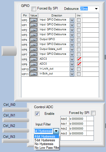
for I2S communication with the AK4430, general purpose IO pins MP6, MP10 and MP11 are set to SDATA_OUT0, LRCLK_OUT and BCLK_OUT respectively.
to read the position of the two control knobs (Volume & Balance), pins MP8 and MP9 are set to the inputs of the 8-bit auxiliary ADC: ADC3 and ADC0.
to control the clip-indicator LED, pin MP4 is set to Output GPIO.
next, how do we set up the EEPROM?
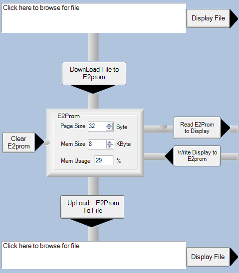
the DSP uses a 24FC64FT EEPROM from Microchip. it has a capacity of 64kb, which is 8kB, so that is how i set up my Mem Size. the datasheet lists a '32-Byte Page Write Buffer', so i have set Page Size to 32 Byte.
now that this thing is set up, i can finally doing something with it.
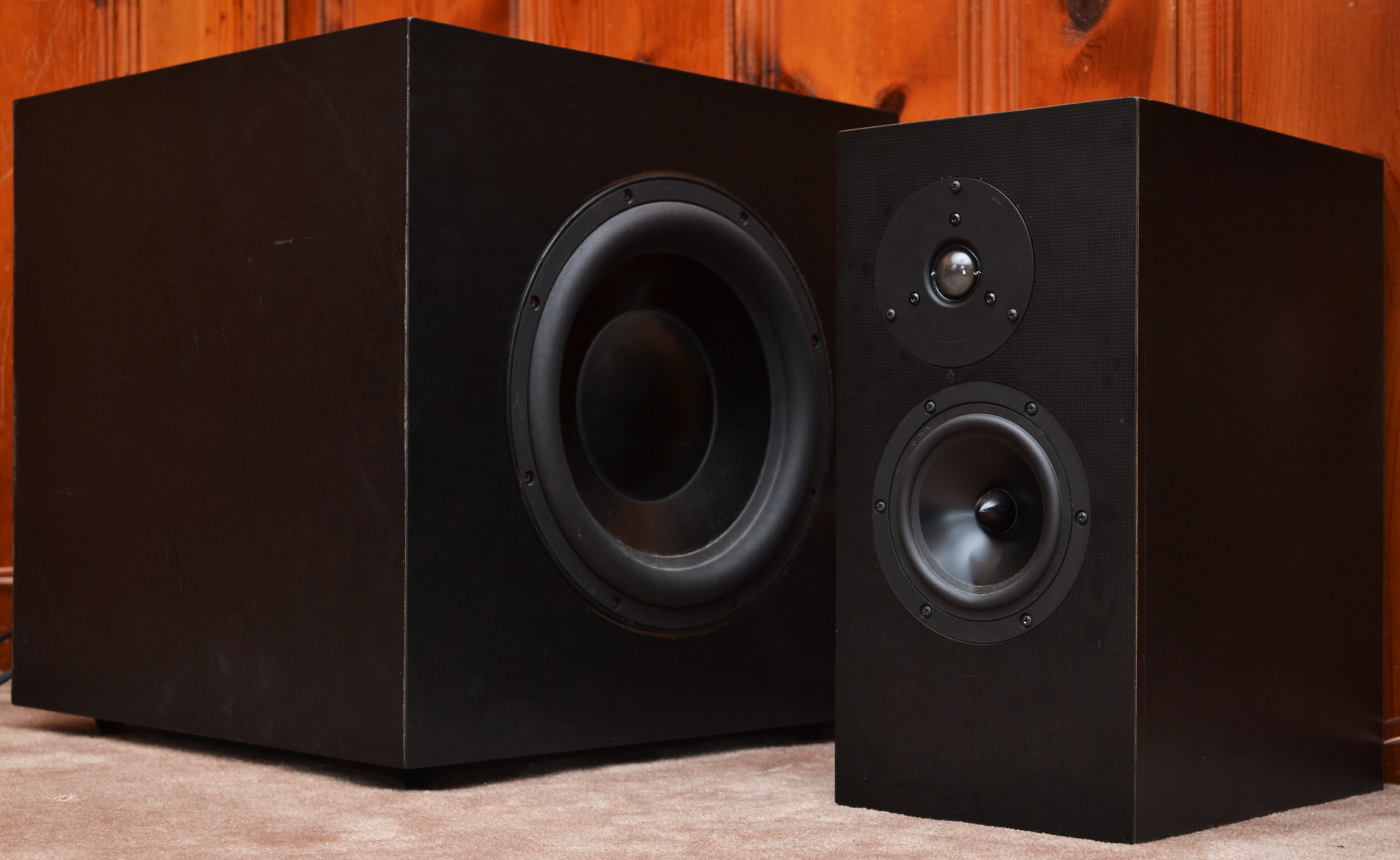
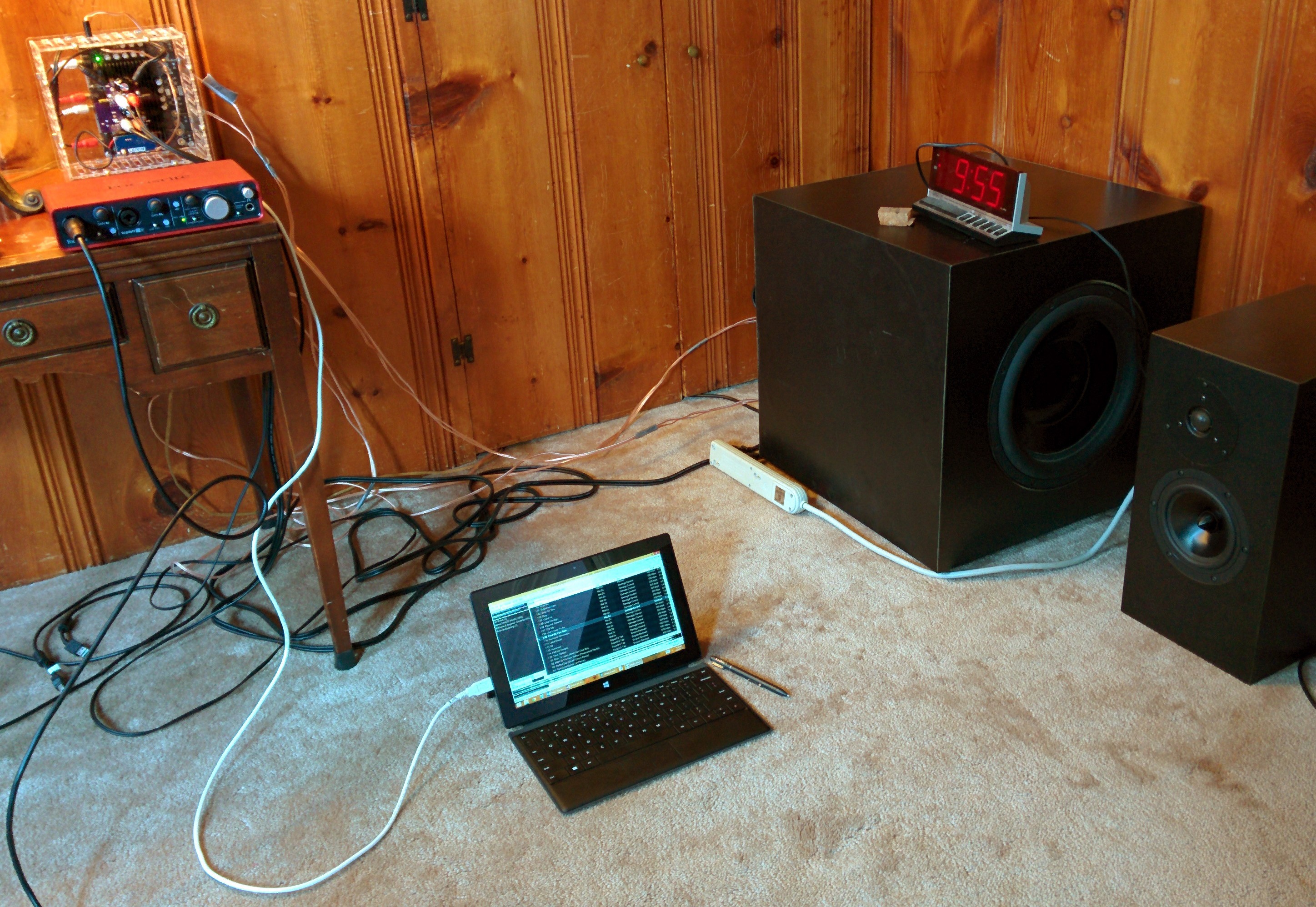
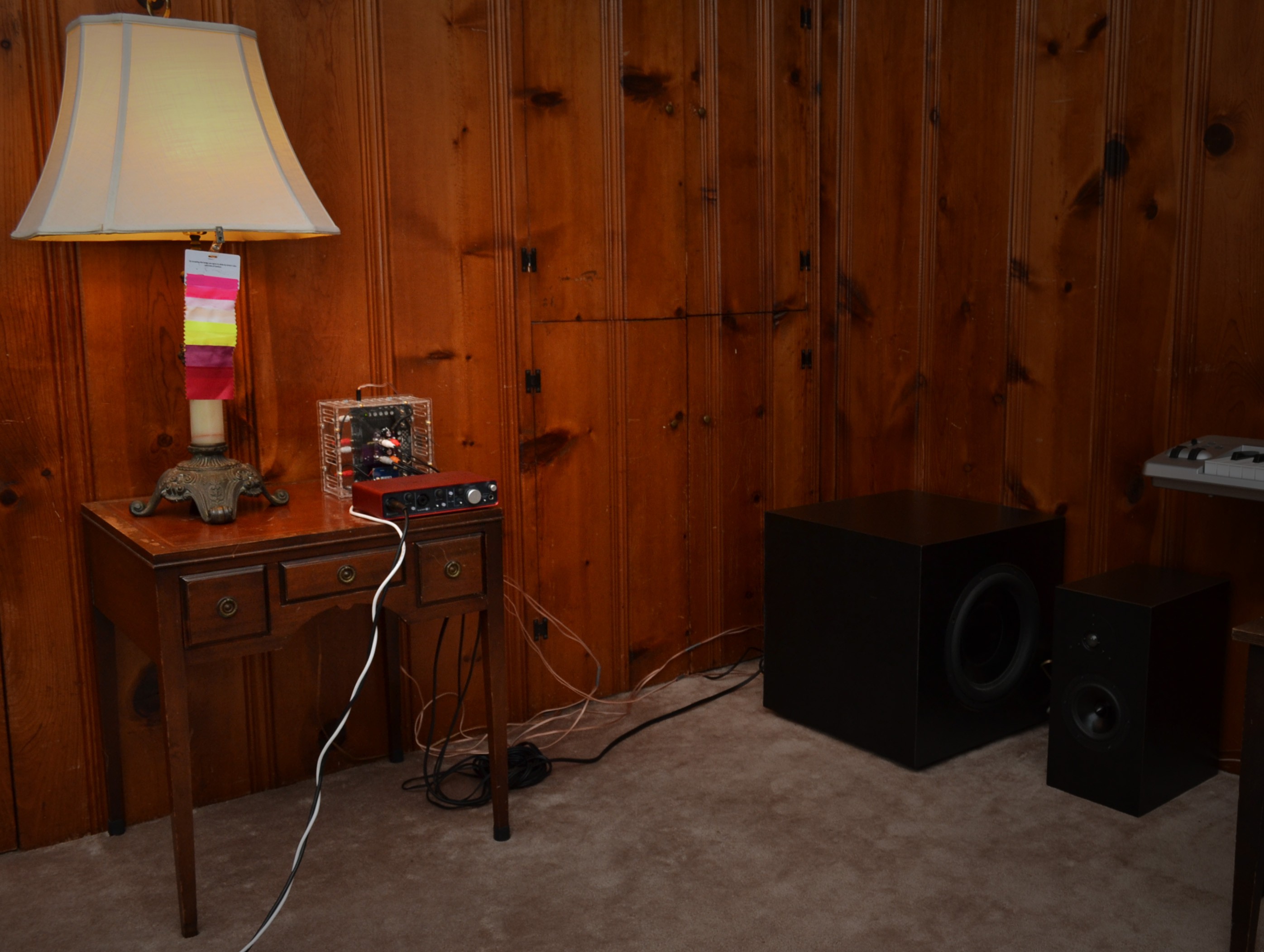
these are the first speakers i ever built. on the left is a 12-inch subwoofer using a Dayton Reference driver and an M&K plate amplifier. on the right is one of the two biamplified main speakers, using Dayton tweeters and woofers. i will program DSP 01 to be an equalizer & crossover for the entire system, with the internal 4x100W amplifier driving two tweeters and two woofers, and the two line-level outputs controlling the subwoofer through the M&K plate amplifier.
but that is too much for all at once! first of all, let's get it working with just one main speaker.
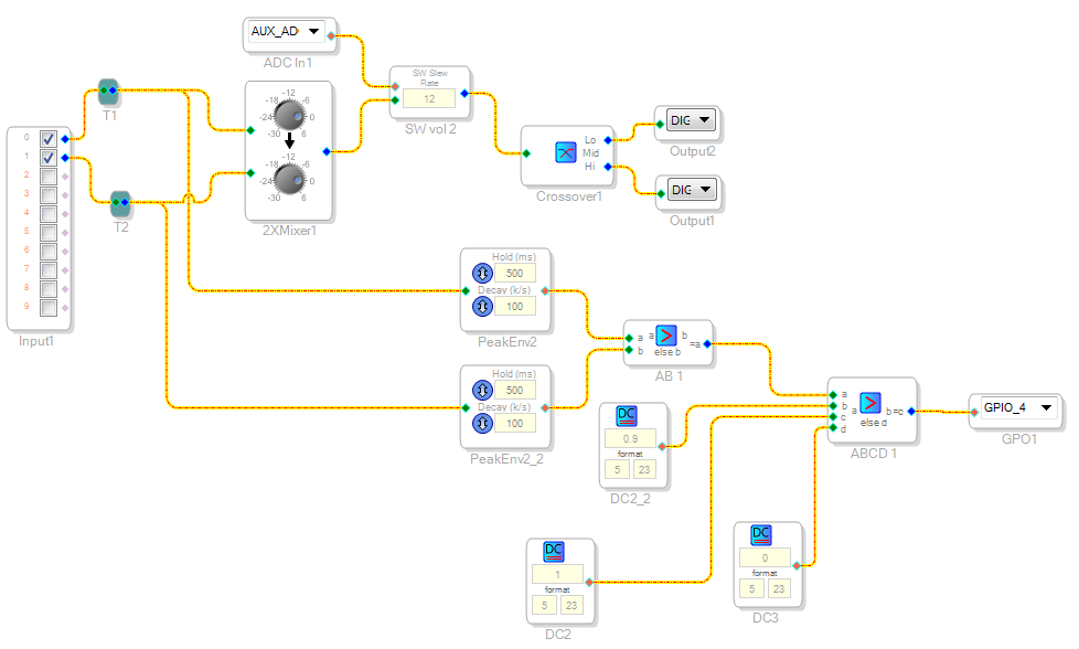
here is the signal flow for controlling one main speaker.
the lower branch (starting with PeakEnv2 and PeakEnv2_2) checks if the DSP's inputs are clipping. if the input signal amplitude exceeds 90% of maximum, the clip-indicator LED turns on for 500ms.
the upper branch is the audio signal processing, and contains the following blocks:
- 2XMixer1: a block which combines the left and right audio inputs to produce a mono signal - we're only testing one speaker after all.
- ADC In1: a block which reads the position of the Volume Control knob.
- SW vol 2: a volume control block controlled by the position of the Volume Control knob.
- Crossover1: a block which splits input frequencies between the tweeter and woofer.
- Output1 & Output2: blocks which send incoming audio to the woofer and tweeter.
Crossover1 is set up as follows:
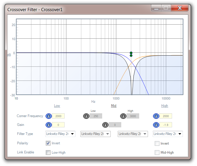
the frequency split between tweeter and woofer occurs at 2000 Hz, using 4th-order Linkwitz-Riley filters. as the tweeter is more sensitive (louder) than the woofer, its relative gain is reduced to -1.9dB. the woofers and tweeters seem to be wired in opposite directions; a positive voltage causes one to move forwards and the other backwards. to make them move in the same direction, the woofer's polarity is inverted.
this is the bare minimum of signal processing required to test this speaker. let's measure it!
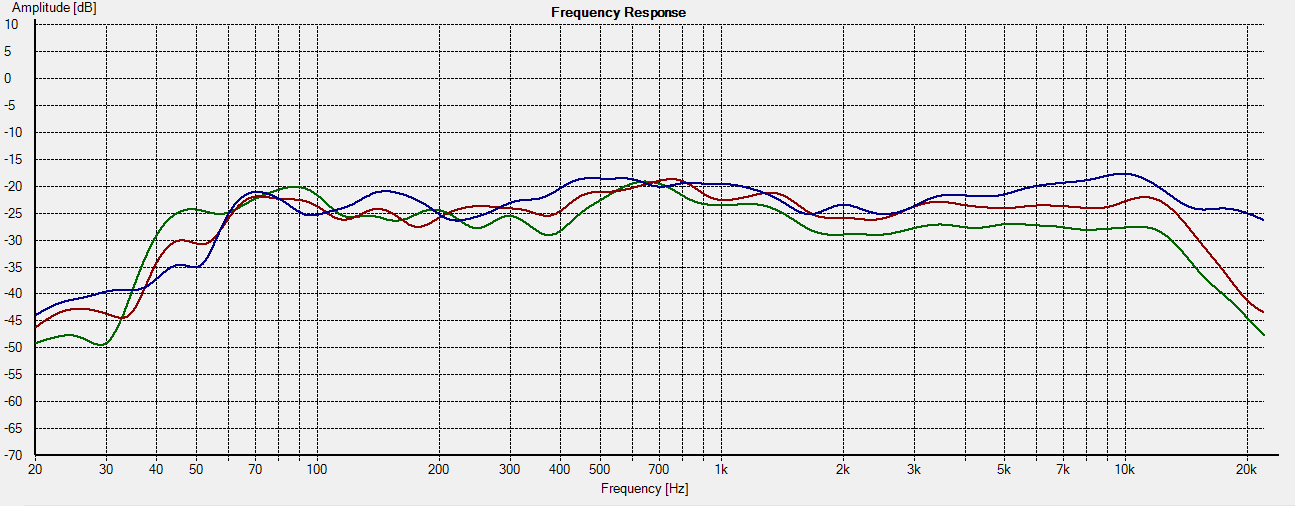
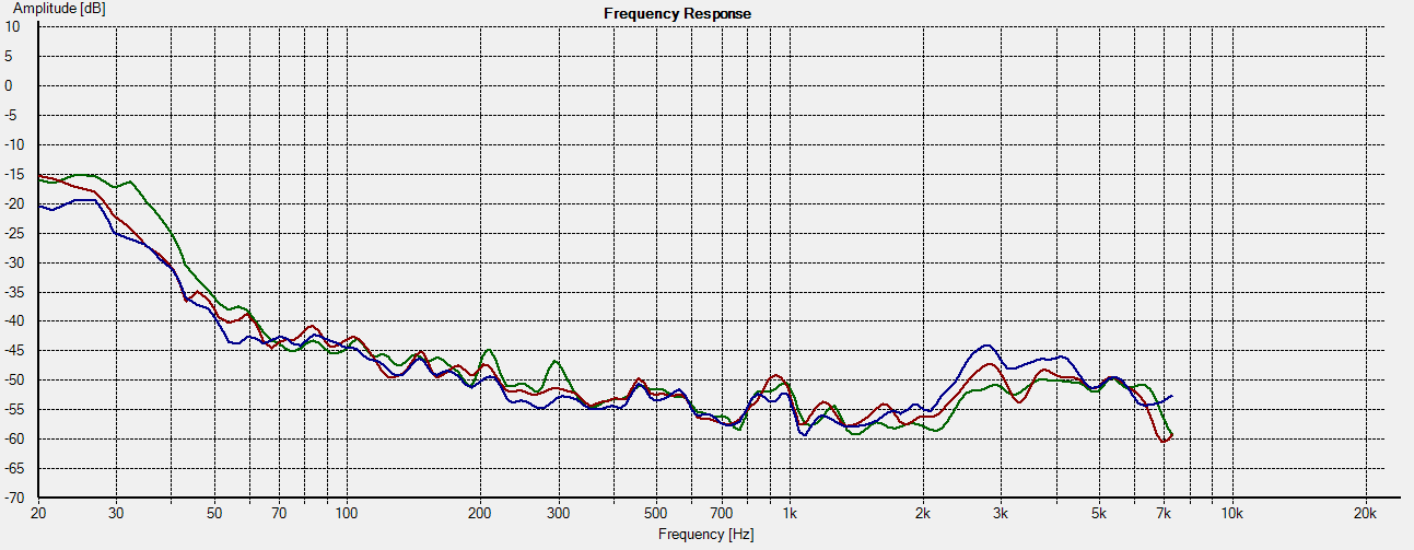
the following frequency-response measurements were performed using HOLMimpulse with a calibrated Behringer ECM8000 microphone, fed into the preamps of an EMU 0404 USB. the frequency-response of an 'ideal' speaker is a completely horizontal line, independent of SPL (loudness) or angle of measurement.
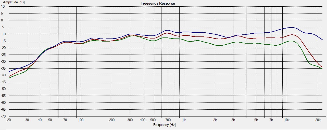
(frequency response, measured 12 inches from speaker at various horizontal angles. 0 degrees (blue), +45 degrees (red), +90 degrees (green) )
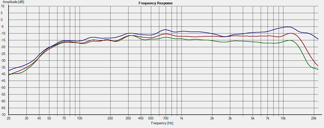
(frequency response, measured 12 inches from speaker at various horizontal angles. 0 degrees (blue), -45 degrees (red), -90 degrees (green) )
 (frequency response, measured 5 feet from speaker at various horizontal angles. 0 degrees (blue), +45 degrees (red), +90 degrees (green) )
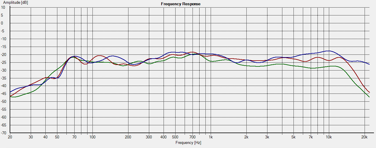 (frequency response, measured 5 feet from speaker at various horizontal angles. 0 degrees (blue), -45 degrees (red), -90 degrees (green) )
i don't own an anechoic chamber, nor am i going to measure my speakers in the middle of a field. performed in a living room, these plots show lots of ripples caused by room modes and delayed indoor reflections, which have little to do with the speaker design. trying to remove every ripple through equalization is a terrible idea!
i ask these questions before deciding to fix a ripple with equalization:
- does the ripple show up consistently at most measurement angles?
- do i understand what is causing this ripple?
in all of these plots, there is one clear target for equalization: the baffle-step.
baffle-step is a phenomenon which plagues most box speakers. measured on axis, it causes the high frequencies to be up to 6dB louder than the low frequencies:
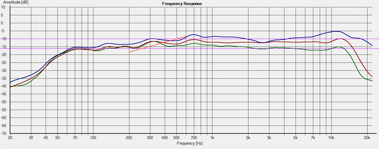
(baffle-step indicated on frequency response. a 6dB boost appears between 250Hz and 500Hz at 0 degrees (blue) )
this trend shows up in every plot! let's explore why.
a speaker is required to produce sounds across the whole audible range of frequencies, from 20kHz to 20Hz. over this range, the wavelength of sound will vary from 0.6 inches (at 20kHz) to 50 feet (at 20Hz).
every box speaker has a front surface, or baffle, on which the drivers are mounted. a typical speaker baffle may be 8 inches wide. short and long wavelengths will experience this baffle differently, just as an ant may be blocked by a pebble, but an elephant will trod right over it.
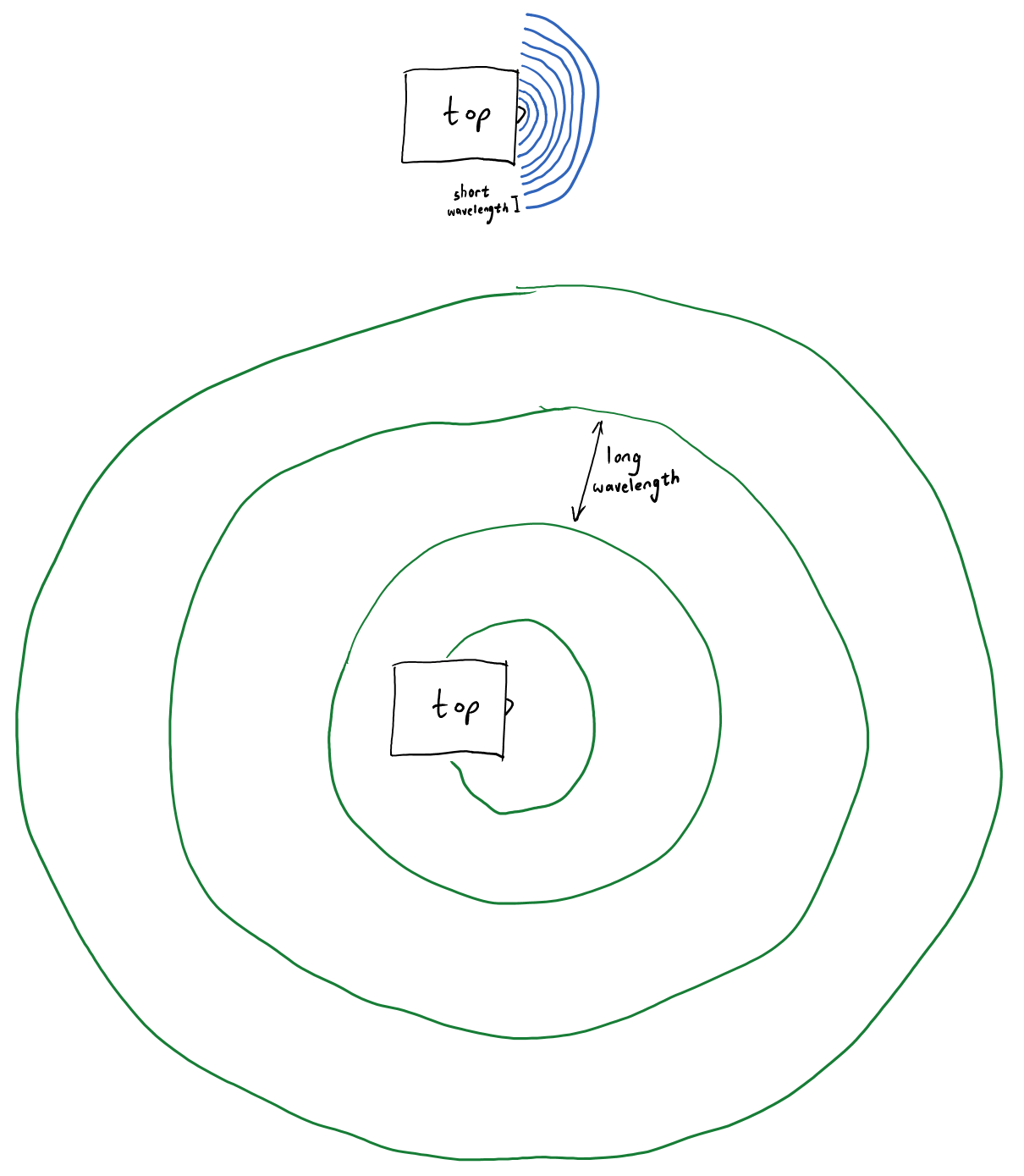 (short wavelengths (blue, upper) and long wavelengths (green, lower) radiating from a speaker)
the high frequencies with short wavelengths will experience the baffle as a huge wall behind the driver. this forces them to radiate forwards in the shape of a half-sphere.
the low frequencies with long wavelengths will barely notice the baffle. they will radiate in a spherical pattern because the baffle offers no resistance.
the high frequencies, radiating in a half-sphere, are twice as concentrated as the low frequencies, which radiate into a full sphere. this is why the high frequencies seem up to 6dB louder when measured. note that in both cases, the same amount of sound pressure is being put into the room. the only difference is half the low-frequency energy is fired sideways and backwards!
the baffle-step is the set of frequencies over which we observe this 6dB rise in measured response. there is no complete way to fix it with equalization because its effect differs with measurement angle. we'll just put a bit of boost (3dB) in the low-frequencies, to patch over the damage. the only complete fix is a speaker design which avoids baffle-step altogether (and that will be a future project!).
baffle-step compensation is the only equalization we will perform in this project. so here we go.
 (go tinycomputer go!)
here are the requirements for our signal-processing chain:
- tweeters emit frequencies above 2kHz
- woofers emit frequencies between 80Hz and 2kHz
- subwoofer emits frequencies below 80Hz
- tweeters have 1.9dB less gain than woofers
- baffle-step compensation of 3dB between 250Hz and 500Hz
and here is the required frequency response of the DSP:
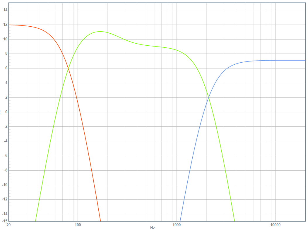 (DSP frequency response: subwoofer (red), woofers (green), tweeters (blue) )
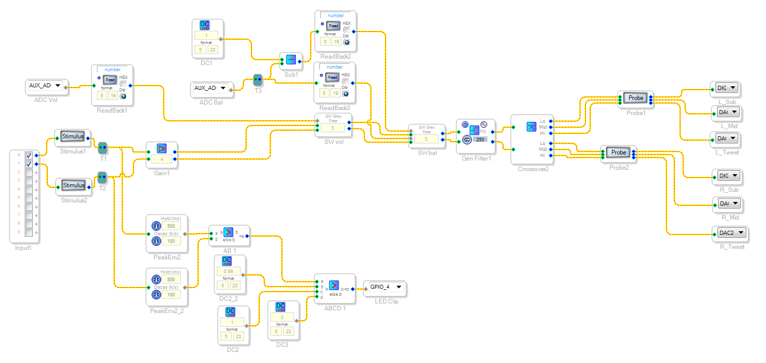
below is my first shot at building a DSP chain which meets these requirements. it includes an additional, 2-input SW slew rate block (SW bal) to implement the left-right balance knob. Gen Filter1 performs the baffle-step compensation.
here is a zoom-up of the 3-way crossover block, Crossover2:
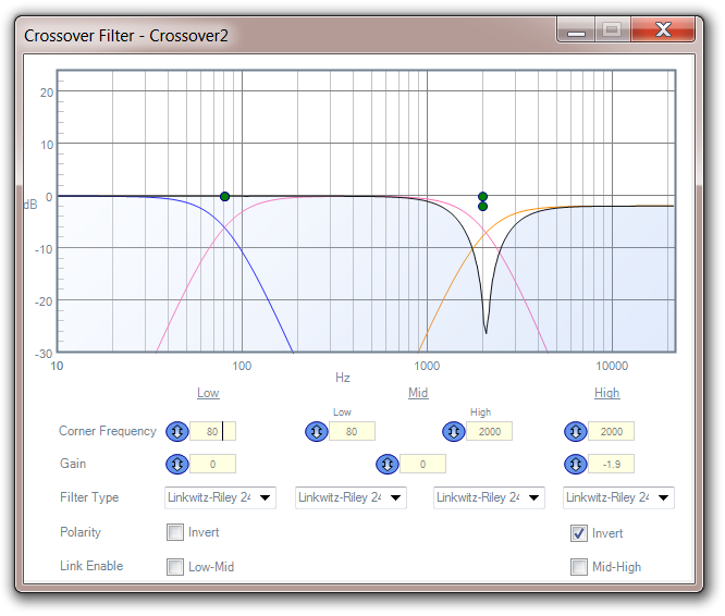 (as before, the tweeter is inverted relative to the midrange)
does it work? yes. very well.
i soon realized that i wasn't using the left-right balance knob at all. i decided to modify the signal chain to give it a new purpose. here is the final version of the signal chain - the 'balance knob' now switches between two modes: main speakers only and main speakers + subwoofer.
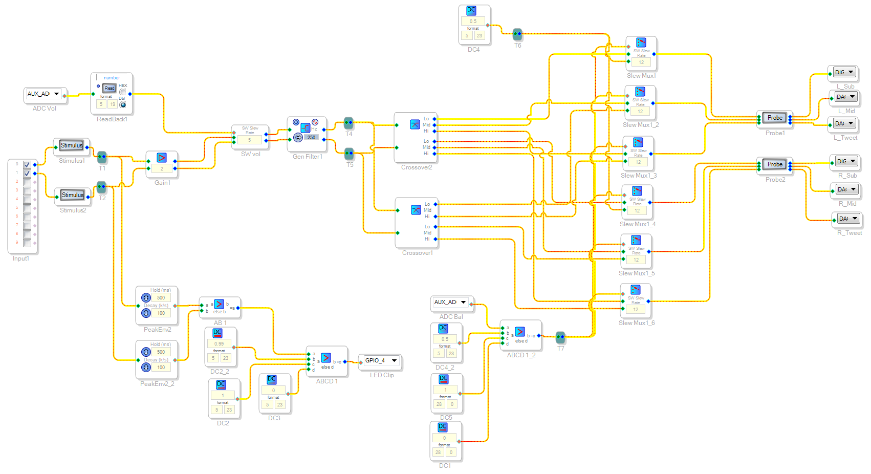 (the Slew Mux blocks are just multiplexers to switch between modes)
and there you have it! it is a DSP. it's reprogrammable, ultra-compact and reasonably cheap. but is it better than analog?
 (Total Harmonic Distortion of one main speaker, measured at 12 inches from speaker at various horizontal angles. 0 degrees (blue), +45 degrees (red), -45 degrees (green) )
i don't know. but it is very, very nice.
Tshen2 2014
Discussions
Become a Hackaday.io Member
Create an account to leave a comment. Already have an account? Log In.