Close
0%
0%

Simulation Source Measurement Unit

Combine core elements of lab equipment into one platform. Goal is to cover the topics present in an ECE101 classroom and lab.

Similar projects worth following
The Simulation Source Measurement Unit (SSMU) will integrate functions from multiple lab bench tools for an accessible way to teach electrical engineering fundamentals.

The SSMU can be controlled remotely via a wireless link (nRF24L01+) or directly via USB. The user will be able to simulate their circuit with ngspice and plot this data alongside the values recorded from the hardware. Target cost for parts and PCB is $25-$35.

Current spec list:

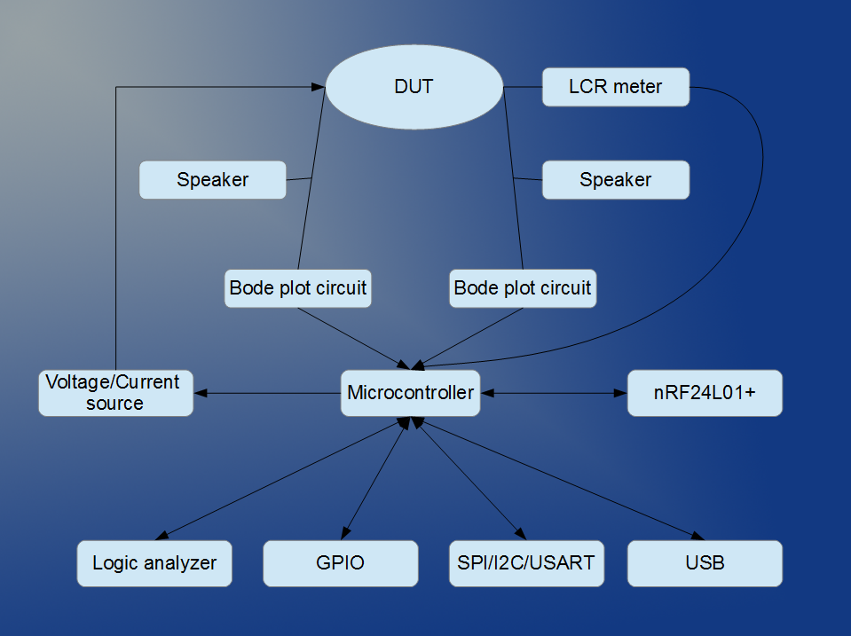
1-2* voltage sources (-5V - 5V, sourced from 12bit 1MSPS DAC)
1 current source (+/- 15mA)
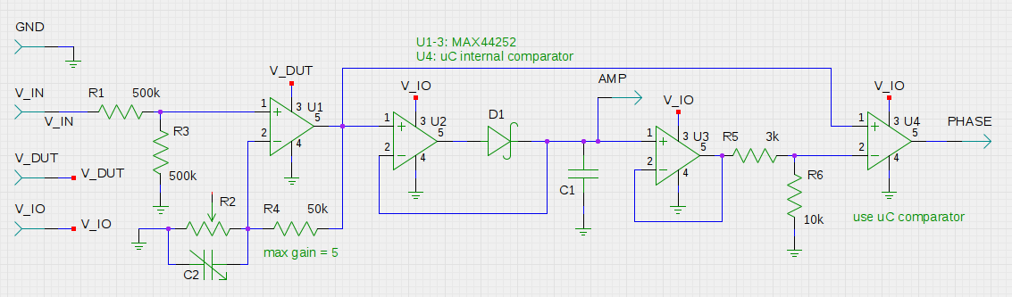
2 voltage measurements (12bit resolution @ 1MSPS, variable gain, AC or DC coupling, 100kHz bandwidth)**
2 current measurements (80kHz bandwidth)
Fixed and adjustable power supply (+3.3V, +/-5V, 0-9V)
Adjustable current limits for 0-9V rail and DAC output
Protocol analyzer (at least I2C, SPI, and UART)
LCR meter
USB and wireless (nRF24L01+) connectivity

*One voltage source is used for the current source but will be accessible when the current source is not in use

**While the microcontroller has support for 20 ADC channels, only two are broken out to the gain and AC/DC coupling circuit.

Concept video:


System design document:


License information:

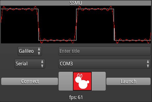
Currently the microcontroller firmware has not been written. However, the base code for the desktop and mobile app uses the libGDX framework:

http://libgdx.badlogicgames.com/

The ngspice circuit simulator will also be included in the final product. I currently don't have plans to rebuild from source:

http://ngspice.sourceforge.net/

  • 1 × STM32L100RBT6 Main microcontroller
  • 1 × AD8276 Op amp for current source
  • 2 × INA213 Current sense
  • 1 × STMPS2151STR 500mA current limit
  • 1 × MAX44251 Dual op amp for DAC amps

View all 9 components

  • Desktop and Android App Status

    BunneyDude08/21/2014 at 04:41 0 comments

    I never got around to cleaning up my initial SSMU app code and posting it to my GitHub. Shortly after I started working on a app that could render shapes requested by an Intel Galileo board over WiFi. It started with the same base code as the original SSMU app and was able to reuse the same communication protocol as well. 

    Now I'll be able to fully merge the changes from the original SSMU and the WiFiScreen code since the goal is to have both wired and wireless communication. As a bonus, since my previous code was developed for the Intel Galileo board, it will be easy to port the relevant portions to a BeagleBone Black or Raspberry Pi. This way the smaller single-board computer can act as a hub and translate the nRF24L01+ payloads to WiFi ones. 

    Leveraging these common devices means that I don't need to increase the SSMU BOM just to include a WiFi radio and can instead use the much cheaper (~$1) nRF module.

  • Updated Bode plot circuit

    BunneyDude08/20/2014 at 06:31 0 comments

    After skimming through some data sheets I noticed the initial voltage buffer wasn't very useful as-is. The MAX44252 only has 2pF input capacitance so to balance out the loading of the DUT's capacitance I added C2 to compensate. For now it's a placeholder until I run more calculations to see what the feasible range of capacitances the DUT will have.

    I've also replaced the discrete comparator for phase measurement with an internal one on the STM32L100RBT6. Originally I wanted to keep the phase output separate so I could easily hook up other microcontrollers and evaluate them as an alternative to the STM32.

    The power rail for U1 isn't finalized since I'm determining to what extent I should protect the SSMU from the DUT area. The idea is to teach someone filters and such using this project but if they build something with too high a Q factor it could release some magic smoke on the board.

  • Selecting the op amps

    BunneyDude08/19/2014 at 07:15 0 comments

    The op amps form the most important analog part of the SSMU - the magnitude and phase measurements of a sine wave (the Bode plot circuits). They also amplify the DAC output for the device/circuit under test.

    I first determined what kind of slew rate I would need. While I planned for a maximum output voltage of 15V, I initially relaxed this down to 9V to make sure I wasn't filtering out any op amps with compelling specs or prices. There are two main frequencies of interest - 20kHz and 100kHz. The first is the required max for audible sound and the second is the cutoff I picked so a filter at 100kHz would do a decent job of attenuating the DAC switching frequency. This calls for a slew rate of 1.88-9.42V/us for 15V max or 1.26-6.28V/us for 9V max.

    Next I looked at the errors introduced by input offset voltage and input bias current. With a 12bit ADC at 3.3V, 1LSB = 0.806mV. There are about 4 op amps cascaded in the Bode plot circuit (1 with up to 5V/V gain).

    Finally, I needed a supply rail up to 9-15V at a reasonable price. Based on these points I've currently picked the MAX44252. It comes in a quad package for $2.64 and while it doesn't quite have the 15V slew rate for 100kHz (8V/us) it does have a pretty good input offset voltage (3-6uV) and input bias current (200pA).

  • Summary of previous work

    BunneyDude08/16/2014 at 06:27 0 comments

    I started kicking around the idea behind the SSMU roughly a year ago. In February threw a MSP430 and Intel Galileo board together for a simple proof of concept. At the time I was focused on getting the software on the Galileo and desktop working. 

    I was pretty happy with the result - the Java program was able to send a ngspice file to Galileo, request a simulation, trigger a series of ADC conversion from the MSP430, and plot the results side-by-side.

    After helping teach an introduction to electronics workshop for the public a few months later, I decided to revisit the SSMU project. I relaxed some of my initial constraints (e.g. through hole components) and focused on integrating more features.

    Currently the analog side of the schematic is mostly planned out. I've made initial choices for the current source and current sense blocks and will be finalizing the Bode blocks next.

View all 4 project logs

Enjoy this project?

Share

Discussions

Similar Projects

Does this project spark your interest?

Become a member to follow this project and never miss any updates