Close
0%
0%

Connected Hand Cycling for the 21st Century

Upgraded physical therapy hand cycle featuring an Arduino and connected vitals recording with monitoring and feedback adjustments

Similar projects worth following
This project was designed with a quadriplegic patient's physical therapy needs in mind. I hacked an existing piece of exercise equipment and built a sensory network to monitor the user's vitals so that the system could make real time adjustments to his activity load and provide visual feedback stimulation with rewards. This module is designed to provide a specialized individual work out program for children, adults, and disabled wheelchair users.

I used an Arduino Mega to gather data from a homemade pulse oximeter, body temperature, and galvanic skin response sensors. The data received from the sensors is compiled to make real time adjustments to the hand cycle's resistance level and to provide progress tracking. It also provides visual feedback through an enhanced display utilizing a 7" Android tablet with ambient sensory back lighting.

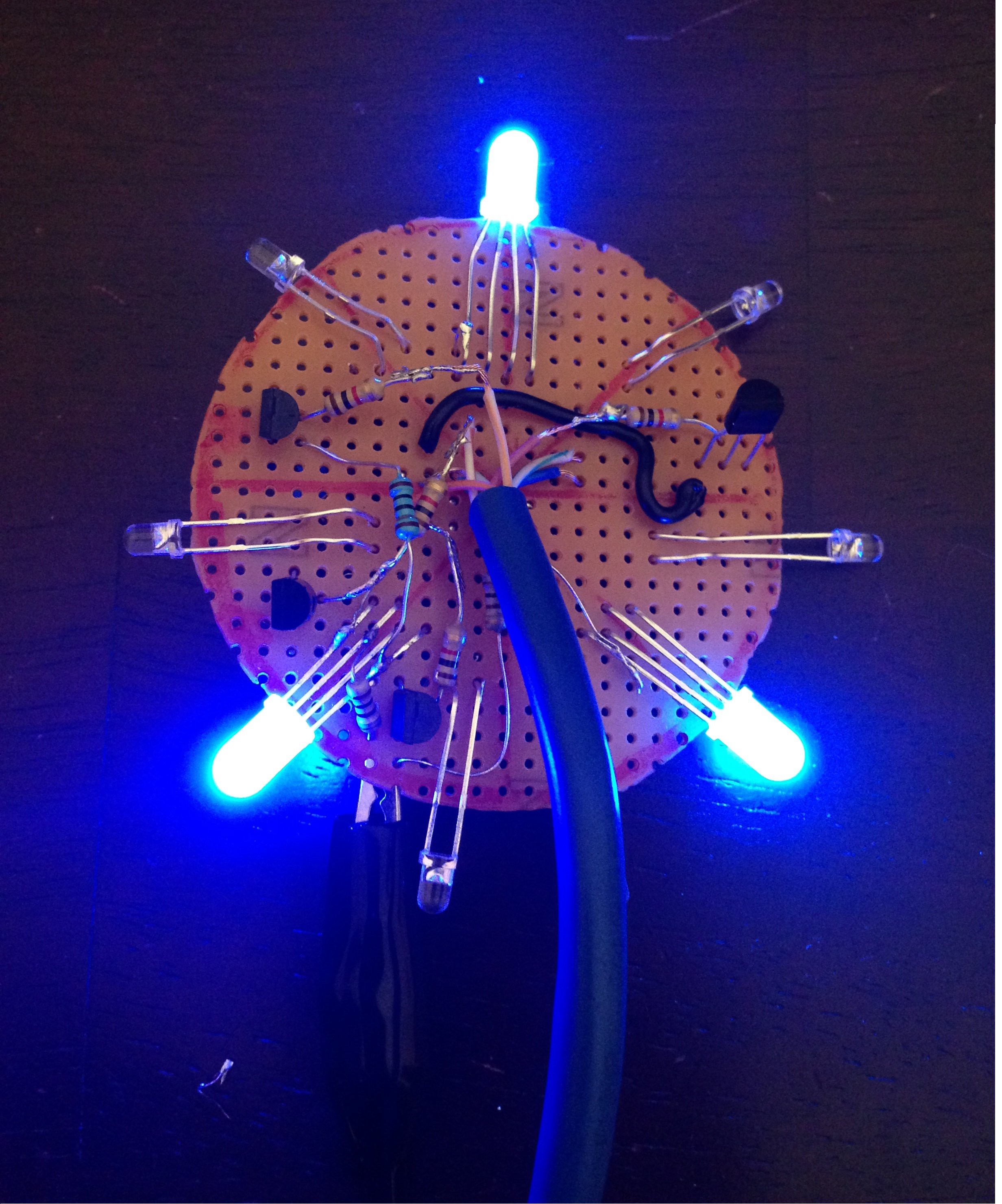
My goal in creating this enhanced hand cycle evolved from watching my quadriplegic brother struggle to utilize his exercise equipment for more than a few minutes before he became bored with the therapy.  He is stimulated by bright colorful lights and my idea to incorporate a 7" Android display with RGB LEDs back light gives him the reward he seeks to continue his therapy as the lights increase in intensity and overall visual appeal the more strenuous his workout.  The Android display will run visual effects pre-set for the user to include nature scenery or the user can view YouTube videos or preferred videos loaded with external memory cards.  This component was further enhanced with the addition of a connected  vitals recording and monitoring system that allows the information to be sent to the Cloud via arduino sending serial data to PC and then directly upload to sensormonkey (https://sensormonkey.eeng.nuim.ie/) so it can be used by family, doctors and therapists. One design objective is to have a stand alone module which can connect to any exercise bike with little modification and is user friendly.  To aid in this goal all design files will be available as open source open hardware files on my Google drive.

https://drive.google.com/folderview?id=0B4BUwT8UAilcazRja29mXzlGWUk&usp=sharing

Working Not working Future Development
Hand speed sensor w/circuit Galvanic skin response analog front end Dual wave length pulse oximeter
Pulse Oximeter Pulse oximeter analog front end Galvanic skin response upgrade w/ analog devices IC
Galvanic Skin Sensor LED driver Sand and paint frame of cycle
Tension Mechanism Arduino Mega code LED driver board with integrated SMD LEDs
Body Temperature sensor w/circuit User interface Digital body temperature sensor
LED backlight Improved Android display holder for increased stability
Android display with holder Develop real time system code
Develop user interface with buttons that allow user to select different workout programs and visual effects

  • 1 × Hand cycle Upper extremity bicycle currently in use by a quadriplegic head injured patient
  • 1 × Arduino Mega used to gather sensor data, control LED back lights, adjust servo motor, and process and relay data
  • 1 × 7" iRulu Android tablet used to display scenery and provide capacitive touch screen for user interface
  • 1 × Sensor network pulse oximeter, body temp, and galvanic skin response as well as hand speed sensor
  • 1 × Ambient back light for tablet RGB LED driven light effects

View all 10 components

  • Updated components

    Hebrewhammer13008/21/2014 at 04:25 0 comments

    My fourth project journal reflects the sensors that I built. These sensors include: body temperature, galvanic skin conductants, pulse oximter and hand speed sensor. I also built the LED backlight with a driver board.

  • Components

    Hebrewhammer13008/21/2014 at 04:24 0 comments

    My third project journal reflects the 3D printed parts I made using my 3D printer. These parts include: servo mount, display holder with integrated tablet holder, and adjustable display mount.

  • Close-up Examination

    Hebrewhammer13008/18/2014 at 03:46 0 comments

    This is a detailed examination of the components of the hand cycle. I found the RPM sensor to be in functional condition.  The tensioning strap was in good physical condition.  There was very little play in  the hand crank  and fly wheel bearings.  I used my digital multimeter to assess the functionality of the RPM sensor and determined that once every rotation the sensor will momentarily ground itself and the rest of the time it will be open.  The original hand cycle had a display that broke off several years ago.  It never functioned  properly but was suppose to display pulse rate, time, distance, speed and calories.  Ideally the placement of the Android display would fit where the previous one was located.


    The above image is the tensioning mechanism for the hand cycle.  Below is the RPM sensor in verified working condition.

    The above photograph shows the sprocket and chain assembly on the hand cycle.  The image below shows the spring used to connect the tensioning strap to the adjustable mechanical tensioner.

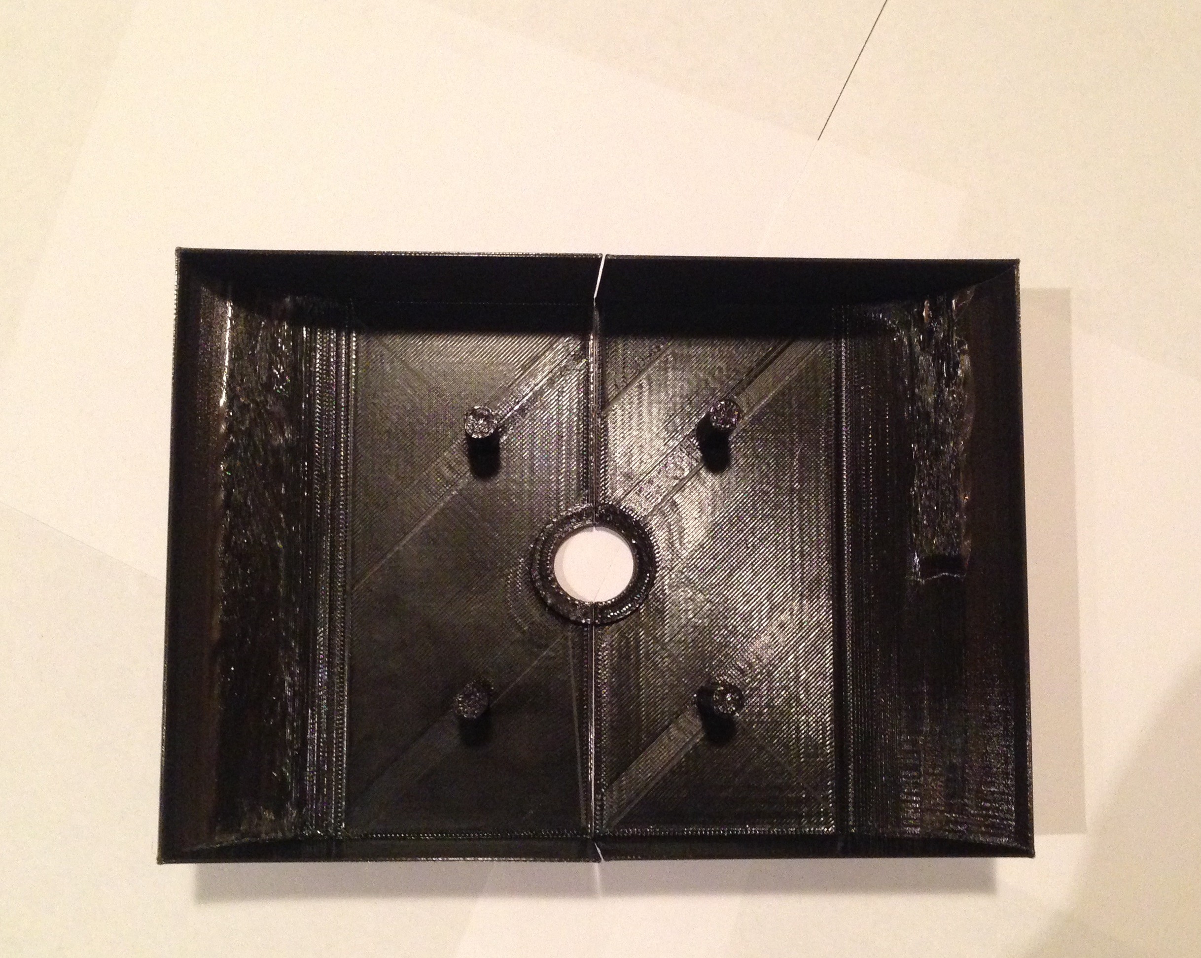
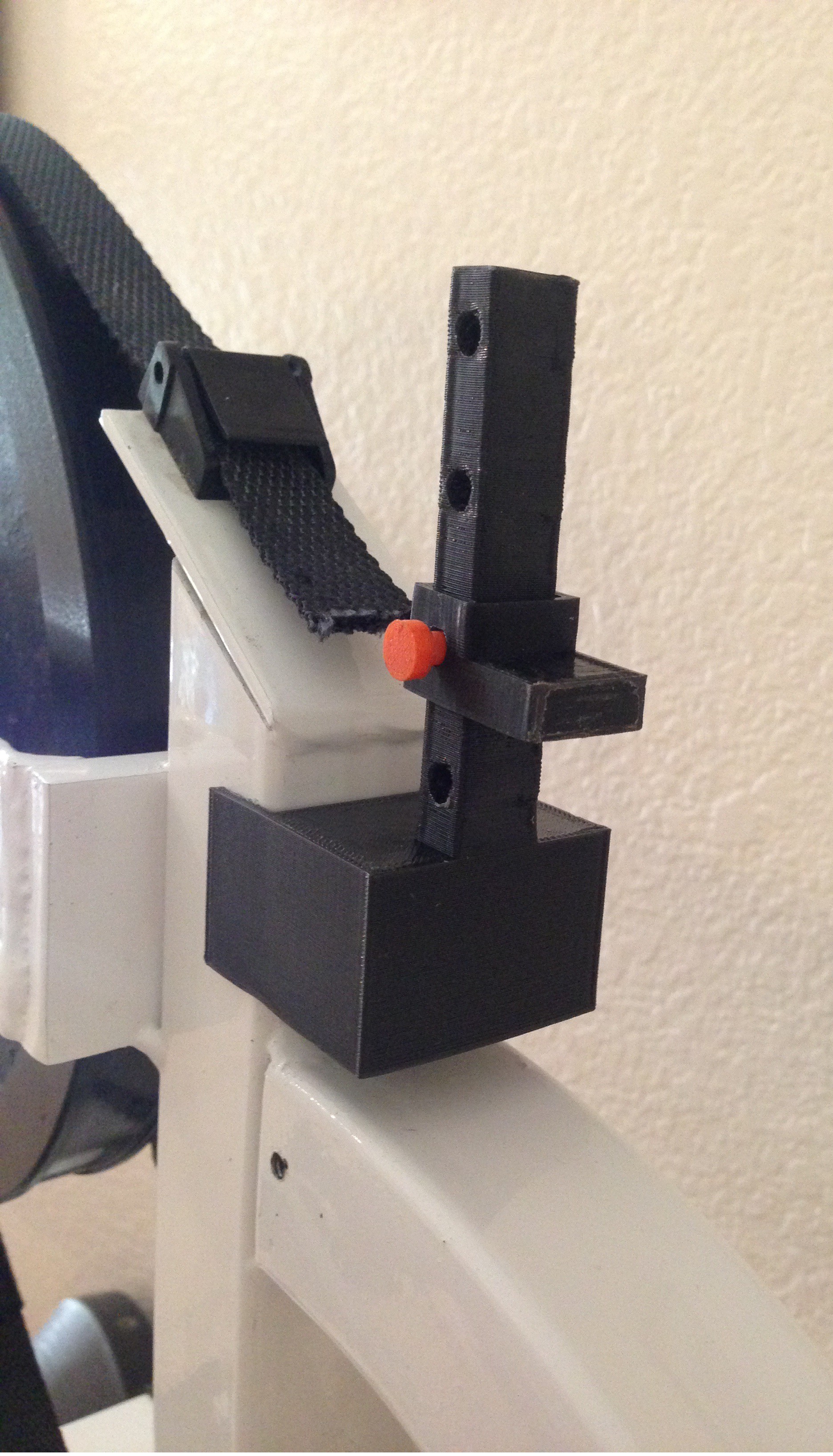
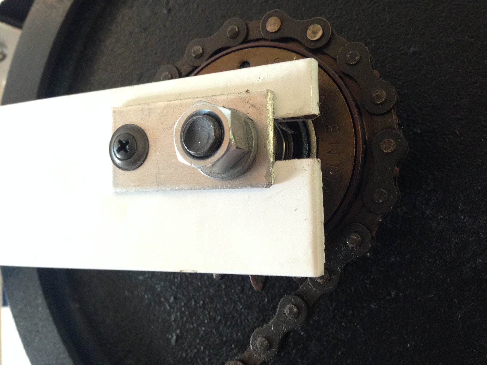
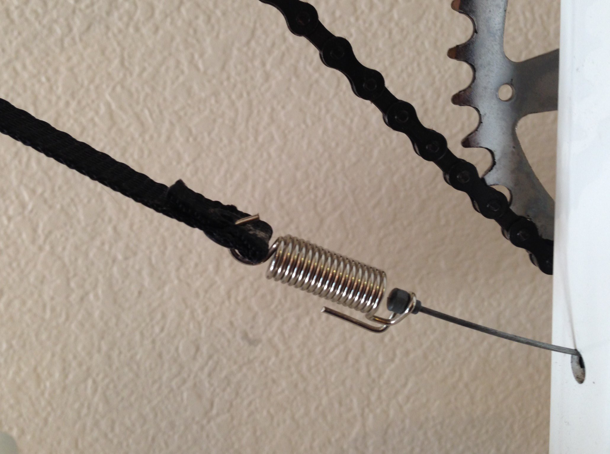
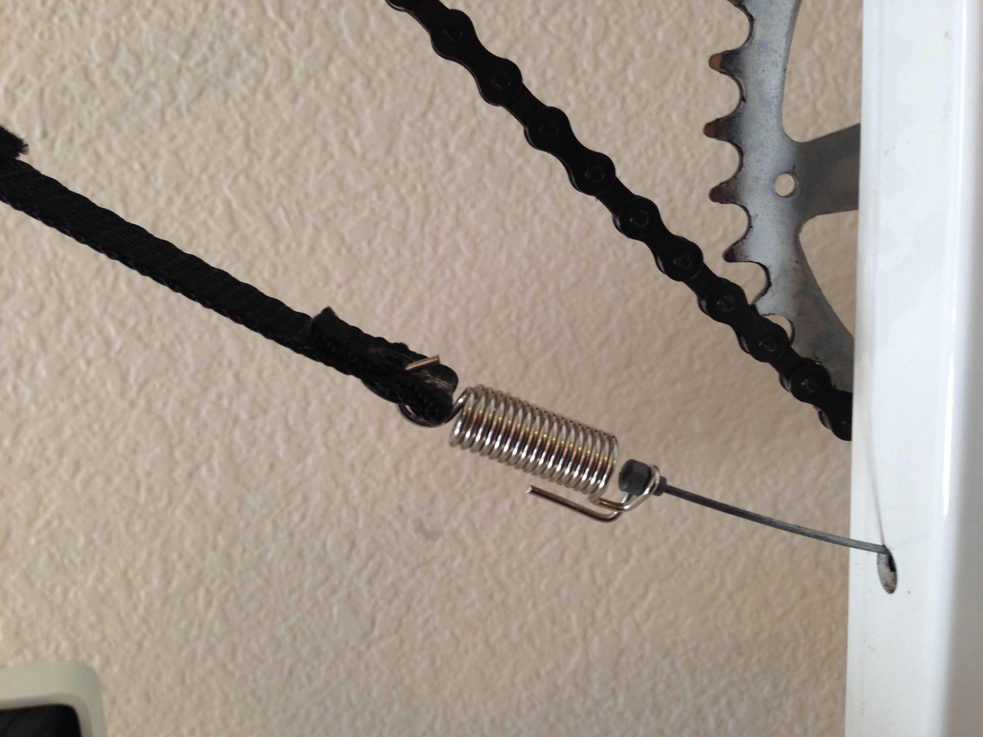
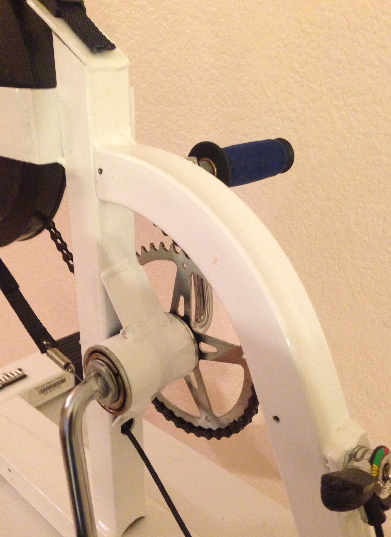
    The image above shows the support frame for the hand cycle.  The placement of the Android display will be in the upper left hand corner at the end of the tensioning strap.
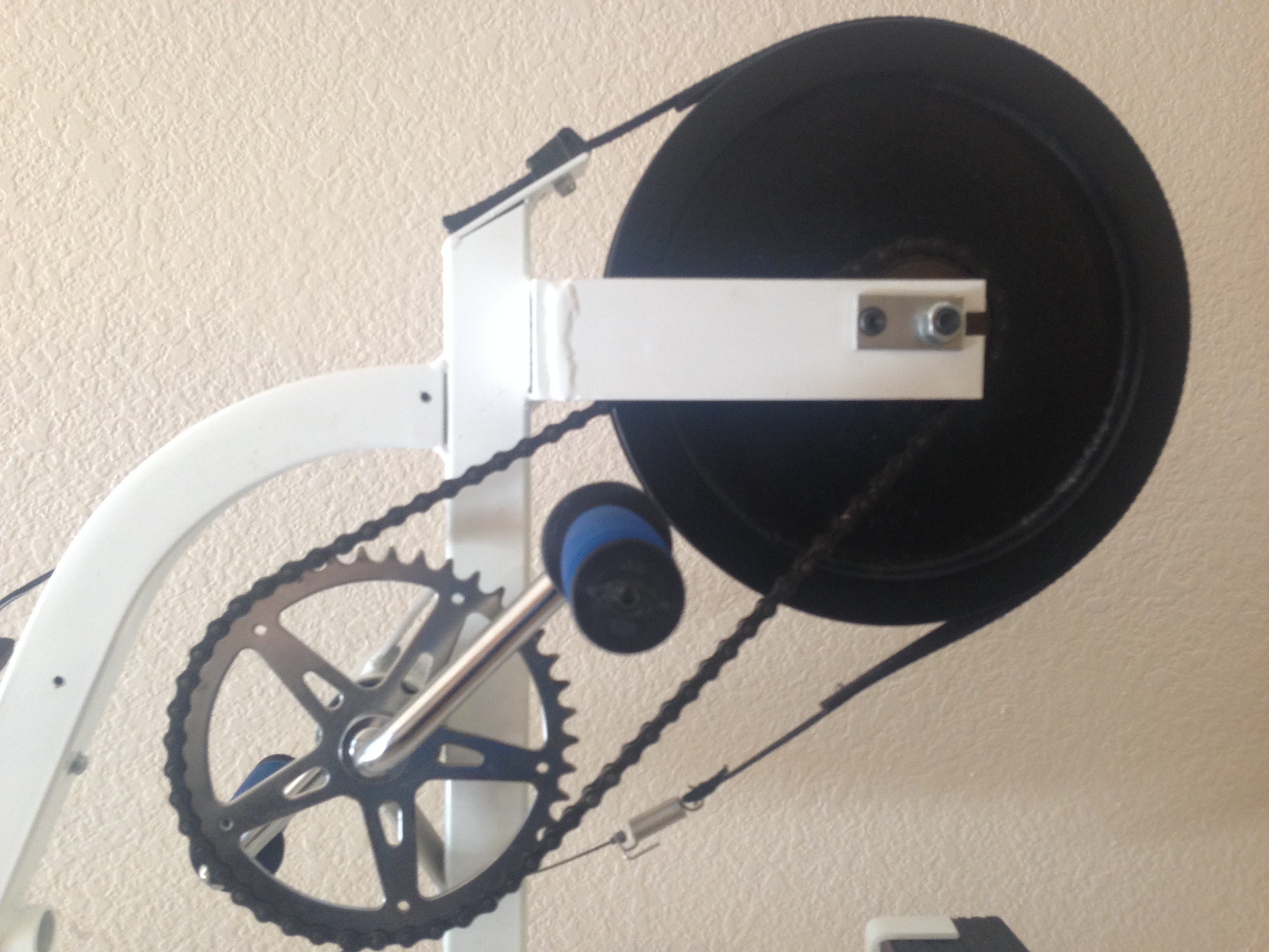
  • Teardown and Assessment of Hand Cycle

    Hebrewhammer13008/17/2014 at 23:42 0 comments

    To start the project, I first dismantled a hand cycle and determined the best way to digitally control the tension and assess the viability of the project.  Upon visual inspection the therapy machine was in good working condition and has enough space for components inside bicycle casing.

    This is an Endorphin Hand Cycle Model EN-300 disassembled. Below shows close-up of hand cycle.

    The top image shows the hand cycle without plastic cover and displays the hand crank, sprocket, fly wheel, spring and support structure.  The bottom image shows a close up of the RPM sensor attached to the flywheel.  This picture also displays a clear view of the tensioning mechanism which I will modify to allow the Arduino to control the tension via a Servo motor.

View all 4 project logs

Enjoy this project?

Share

Discussions

Similar Projects

Does this project spark your interest?

Become a member to follow this project and never miss any updates