The system design overview is very vague due to the nature of this project evolving so much with each project revision new overviews may be produced as necessary along with code and schematics. The first revisions goals are to not spend money, to see how well I can make it without spending money. From there it is still a cheapskate project in nature.
0%
0%
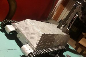
Remote Control Power Wheels
Taking a toy Power Wheels and making it remote control. Making improvements as time, money, and availability of parts allows.
Become a Hackaday.io member
Already have an account? Log in.
Just one more thing
To make the experience fit your profile, pick a username and tell us what interests you.
Pick an awesome username
hackaday.io/
Your profile's URL: hackaday.io/username. Max 25 alphanumeric characters.
Pick a few interests
Projects that share your interests
People that share your interests


 Mateo Estigarribia
 trax
trax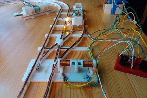
 Szabolcs Lőrincz
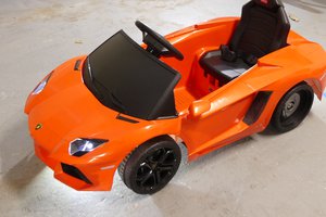
 W. Jason Altice