System Design Document:
A project to enable DIY high-resolution digital readouts inexpensively
Already have an account? Log in.
To make the experience fit your profile, pick a username and tell us what interests you.
System Design Document:
We'll be back with actual build updates tomorrow, but for now I have to vent about printers.
In designing this project, I decided that I would use a printer to print a pattern onto a piece of paper and miniaturize that down onto film stock. I usually give time estimates for these things, and I try to anticipate unknown factors. For printing and calibrating, I gave 2 hours + printer time.
It's the printer time that got me. Turns out that for someone who doesn't print things a lot I have a ton of printers. The problem with that? None of them worked! Here's a taste of the frustration I had in printing the test pattern:
Printer #1: HP DeskJet 3050A. Would not print - dry ink cartridge.
Printer #2: HP DeskJet 3050 (retrieved from storage). Would not print - dry ink cartridge.
Printer #3: HP Color LaserJet 5p (at work). I forgot this one was broken - it won't feed paper through itself properly.
Printer #4: Apple ImageWriter. I didn't actually try to print the codestrip with this printer, but I'd like to point out that a dot matrix printer from 1984 weighing as much as a Prius that makes a sound like a warzone when you print still works perfectly.
Printer #5: HP DeskJet F4200. The only printer that did not have a dry ink cartridge. Of course I had to travel to someone else's house to use it, but it did in fact work.
Note to self: Maybe print something on the inkjets once in a while so the ink doesn't dry out. Alternately, figure out how to get 1200 DPI on a dot matrix.
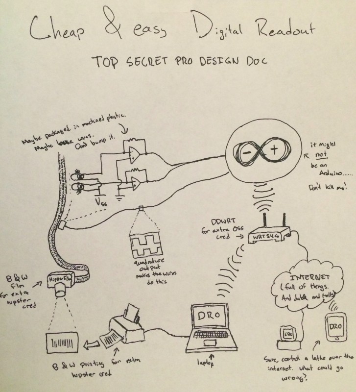
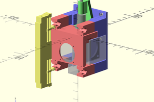
The read head of the project will consist of a pair of photodiodes that will read the pattern on the codestrip and output a quadrature signal to the microcontroller. As the readhead passes over the codestrip, each photodiode will transition from a LOW to HIGH state and back again. Since the photodiodes are offset half a feature width from each other, the position resolution becomes effectively double the codestrip resolution. Through the quadrature technique - monitoring what diode is rising or falling and the state of the other diode - we can determine the direction the readhead is moving.
At this point I have made an example circuit diagram and started prototyping things on the breadboard. I can do the electronics prototyping concurrently with making the codestrip, and getting an earlier start on the electronics will enable me to find and fix any bugs or issues earlier in the process.
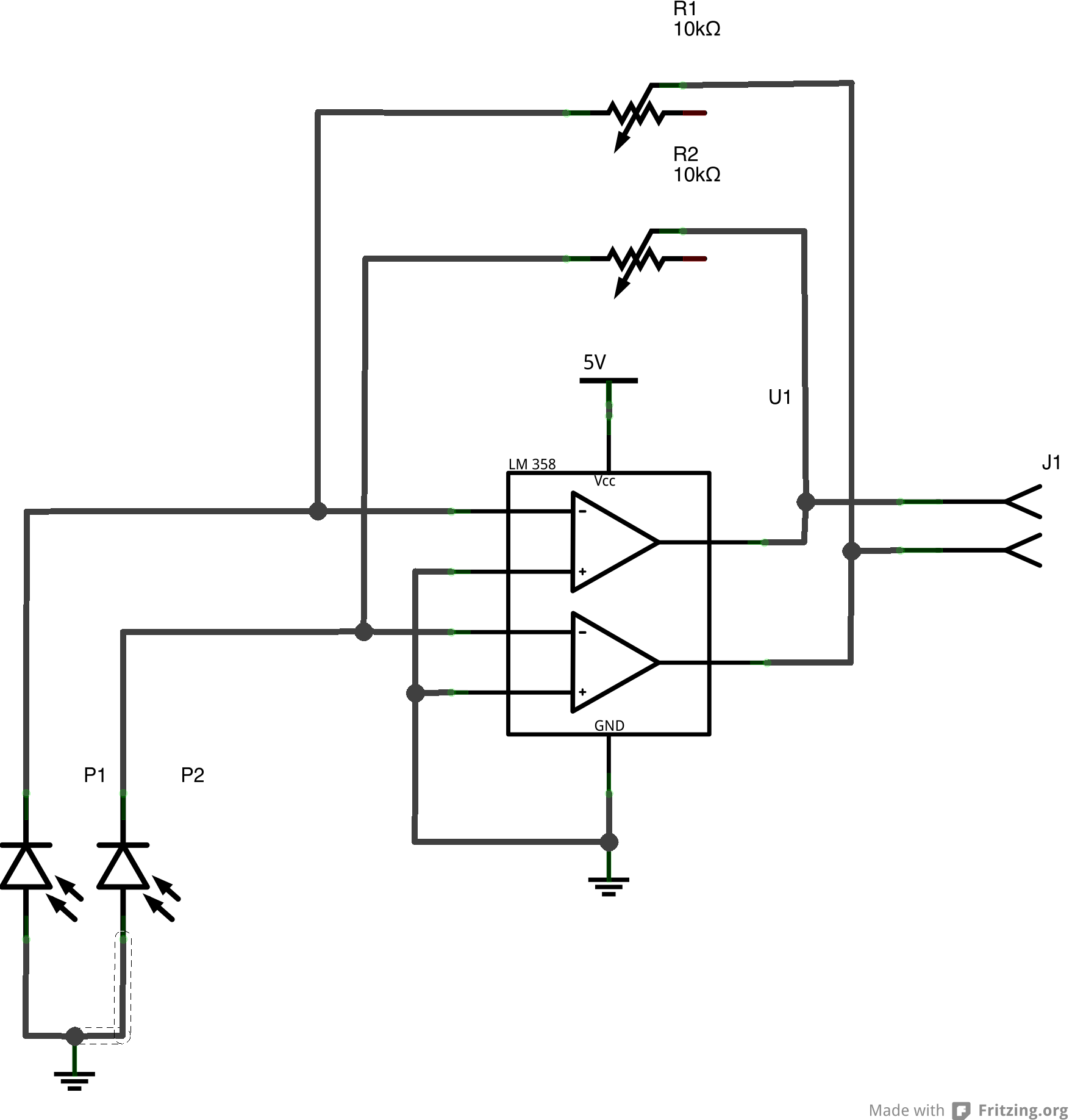
(Schematic Update: the 5v (now ground) on the photodioes was updated - that connection is to Vss)
The circuit is a simple photodiode amplifier - the photodiodes are reverse-biased and amplified by the op-amp. The trimmer resistor in the circuit will allow it to be tuned for various light levels and operating conditions. This trimming capability may not be necessary in the final design, but by having it on the prototype it allows quick testing and recalibration without having to be constantly swapping resistors.
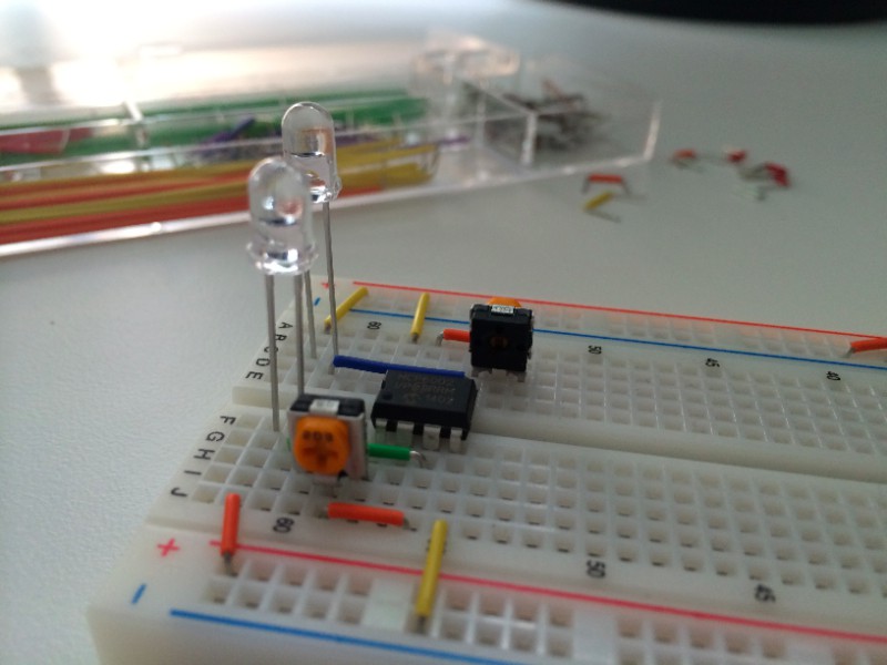
(The breadboard here is not yet fully populated, and the op-amp is a MCP6002, not the LM358 in the schematic. The jumper in the schematic will connect to the microcontroller.)
The first step is to calibrate the lens and camera system so that we know how the size of a feature printed on the paper compares to the size of that feature on the film. Additionally, lenses inherently have some amount of distortion, so that distortion will need to be compensated for in the printouts.
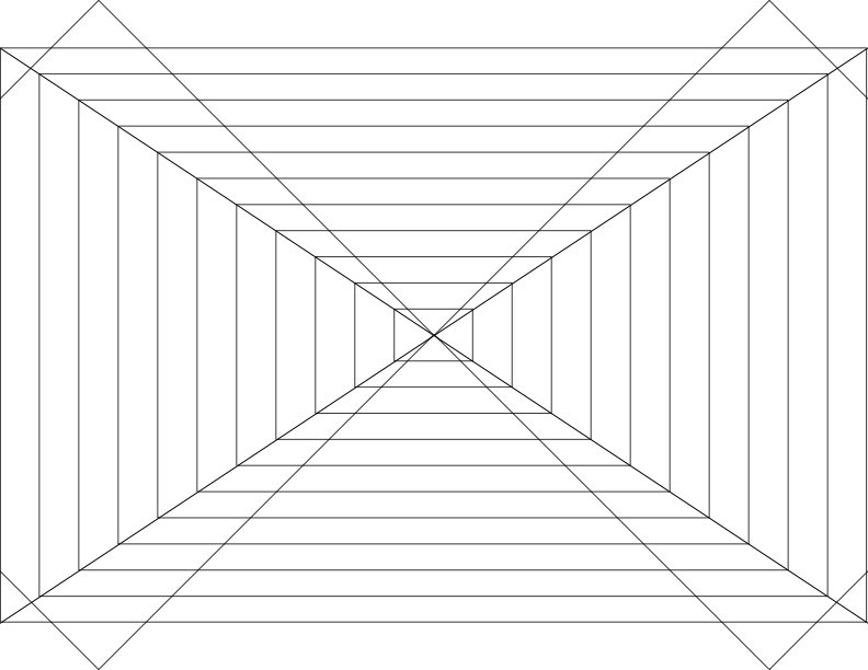
The first printout is a simple targeting and sizing demo to determine the barrel distortion of the lens and get a first idea of the ratio of paper size to film size. The pattern was created in Inkscape and has a pair of horizontal lines - one square, the other following the edges of the film. These lines will be used to center the lens. There are also rectangles of increasing size that are the ratio of a 35mm film image which will be used to determine things like viewfinder coverage and the correct position to get maximum coverage of the film frame.
These images could be captured directly onto the film, developed, and scanned, but I happen to have both a Canon EOS 300 (35mm film SLR) and a Canon EOS 300D (APS-C digital SLR). Since using the digital SLR removes the requirements of constantly developing film, we can iterate a lot faster to find optimal parameters. Since the lens can be put onto either camera body, we can determine the optical characteristics quickly using the DSLR and only use film when we have things dialed in.
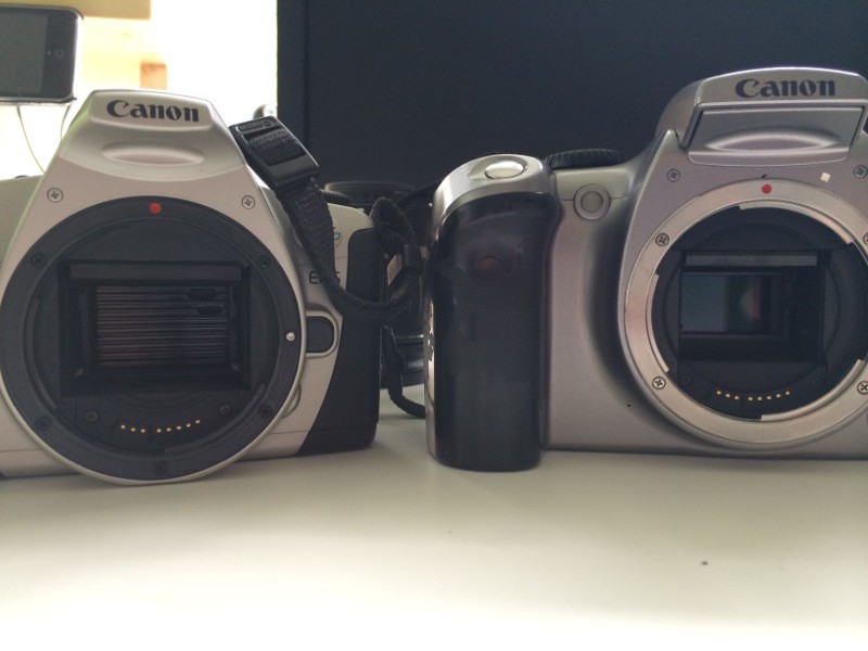
The calibration setup consists of a test pattern positioned on a wall and well lit. The camera is mounted so that the center of the lens is on the same line as the center of the paper. At this step, we have to make a note of where the focal plane is for the cameras. The two camera bodies, while being broadly similar, are different thicknesses and the tripod mounting holes are in different places. That means that the tripod has to be moved a small amount when swapping cameras. Fortunately, SLR cameras have a graphic showing the focal plane of that camera, and since the lens settings will remain the same we simply have to be sure the focal plane is in the same place when swapping camera bodies.
A quick snapshot and the data is taken. I’m using Hugin to compute lens barrel distortion from the digital image.
We are pushing the limits of what is achievable with this optical system. The limits are:
Print resolution of the printer making the patterns
Resolving power of the lens
Resolving power of the film
Obviously, we could simply print the codestrip directly with the printer. Unfortunately, most consumer printers max out at around 1200 DPI, meaning that the printed features would be around 21 microns wide. Such resolution would give about 10.6 micron resolution (about .0004 inch) with the quadrature encoder, an order of magnitude more than the 1 micron (.00004 inch) resolution I would like. Therefore, we will be printing the codestrip and miniaturizing it onto 35mm film stock. This is like increasing the DPI of the printer - a 5 inch square at 1200 DPI miniaturized onto a 1 inch square of film is functionally equivalent of having a 6000 DPI printer. In this case, each feature on film will be 2 microns wide. Since a frame of 35mm film is 36mm wide, there will be 18000 features on the film. Printing at 1200 DPI, that means we’d need at least 15 inches of printed paper. The formula is: feature size = 36mm / (resolution * print_width). 5 micron (.0002”) is easy - 3” at 1200 DPI (remember, because of the quadrature encoder process the resolving power is half the width of the features on the film). 2.5 micron (.0001”) requires 6 inches, etc. Every time we halve the resolution we need to double the length. It’s apparent that 5 micron resolution will be no problem, but getting near 1 micron resolution (2 micron features) will be very difficult.
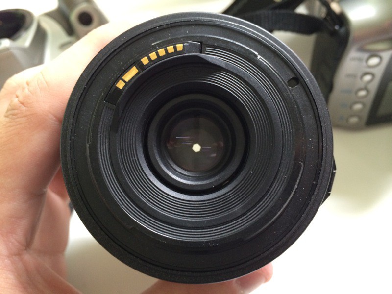
The camera lens presents another area for potential degradation. The lens I’m using (a Tamron 28-80mm zoom lens) is not a extremely high quality lens, so carefully controlling the environment will be crucial to getting the best picture from the lens. Lenses all have some amounts of distortion, particularly barrel distortion. Barrel distortion warps the image outwards or inwards and would reduce the accuracy of the codestrip at the edges. To combat this we will determine what the barrel distortion characteristics of the lens are and predistort the printed code in the opposite way to compensate. Additionally, the lens might have several other, smaller errors - chromatic aberrations, spherical distortion, or perhaps not be perfectly focused to name a few. To begin we will be using white light to illuminate the code, but we could switch to a monochromatic light source to combat aberrations that affect color. We will also be trying different apertures. Stopping the lens down to a very small aperture - f/22 - will make the lens behave more like an ideal (pinhole) lens , and will help correct very minor focus issues (image below). However, the angular resolution of a lens is inversely proportional to the aperture size - a larger aperture will allow the lens to resolve smaller features.
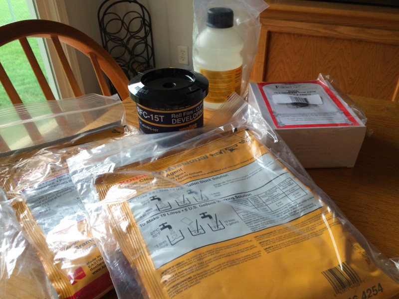
The film I have chosen for this process is Kodak’s T-MAX 100. I chose this film because I actually have the capability to develop it at home - several years ago I set up a darkroom and lab for black and white film photography and decided on T-MAX film at that point (image below). T-MAX 100 is a very good looking film and I have been quite impressed with it for photography. However, the film itself represents another limit - the film must be able to resolve 2 micron features. According to the data sheet, with 1000:1 contrast the film is rated at 200 lines/mm. A “line” is a black to white transition, so that gives us 400 transitions/mm, or 2.5 micron features. That figure is very close to the desired 2 microns, so the hope is that we will be able to push the film to that level by carefully controlling exposure, focus and having extremely high contrast.
By carefully controlling as many parameters as possible I hope to be able to produce 2 micron features on film. 5 micron should be very possible, and I would even be happy with 3 micron features. But obviously I’d like to get as small as possible,...
The hardware I’m using for the optical transfer portion of this project are a Tamron 28-80mm EF-mount lens and two camera bodies: a Canon EOS 300 35mm film SLR (also known as the Canon Rebel 2000) and a Canon EOS 300D digital SLR (also known as the Canon Digital Rebel). These cameras were produced around the same time and are very similar to each other in features, aside from the fact that one is a film camera and the other digital.
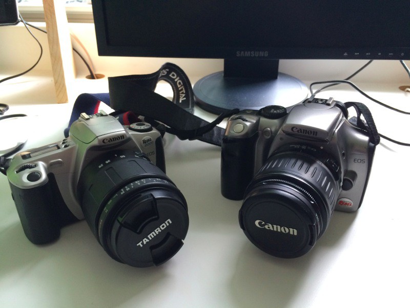
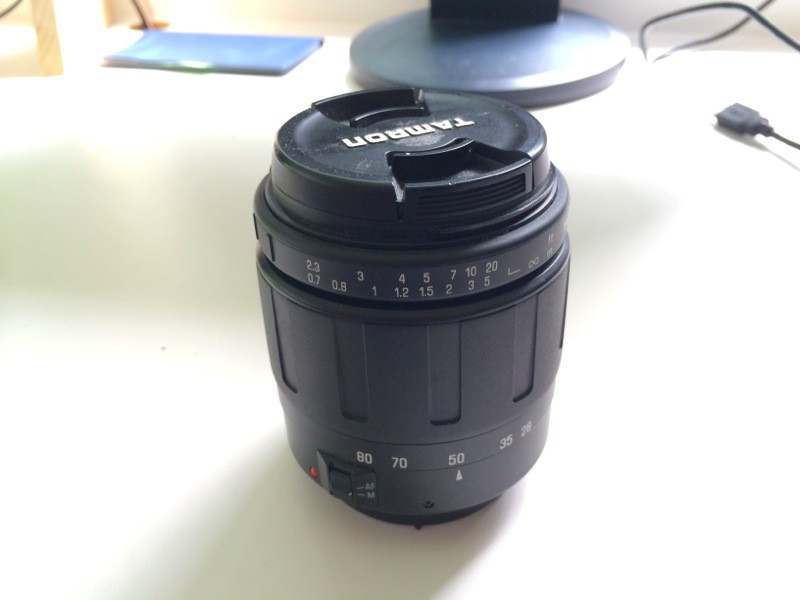
I collected this hardware over a number of years, and it’s just a happy coincidence that the two bodies are so similar - I did not purposefully seek out similar bodies. In fact, the film body was included with a pair of lenses that I bought.
The scales will be made on black and white film stock. A pattern will be printed with a standard consumer printer and then photographed to miniaturize it onto the film.
The readers will be made from a pair of infrared photodiodes and an infrared LED. As the codestrip passes between the LED and photodiode it will block the light and create a changing voltage over the photodiode. We will use two photodiodes and monitor those voltage changes to track the position of the read head on the strip.
The control box and software will consist of a microcontroller to accept the photodiode input and do basic conversion from encoder counts to distance and basic machine safety functions. However, unlike similar commercial offerings, the control box will not have a display, or in fact any inputs or outputs save for a network connection. This connectivity will allow very flexible and feature-rich front ends to be created for the system and run on almost any bit of display hardware possible - from a laptop to a tablet or even a phone. And because the data is being processed by a powerful phone, tablet or laptop processor we will be able to do computationally expensive things that are simply not possible on a microprocessor, such as shape inspection using a probe, lathe workpiece runout inspection and quick vise alignment.
 rolmie

 E/S Pronk
 theschlem