 Joseph Turner
Aim of the Project
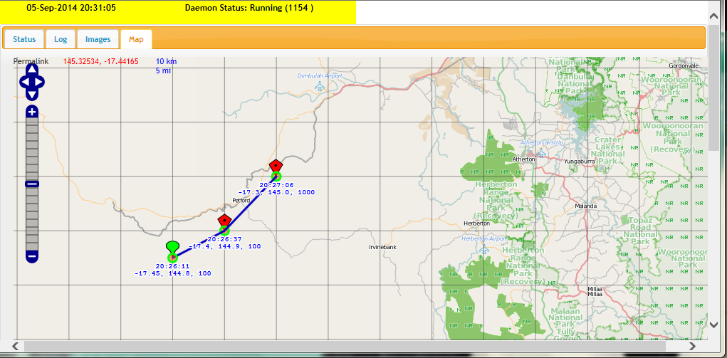
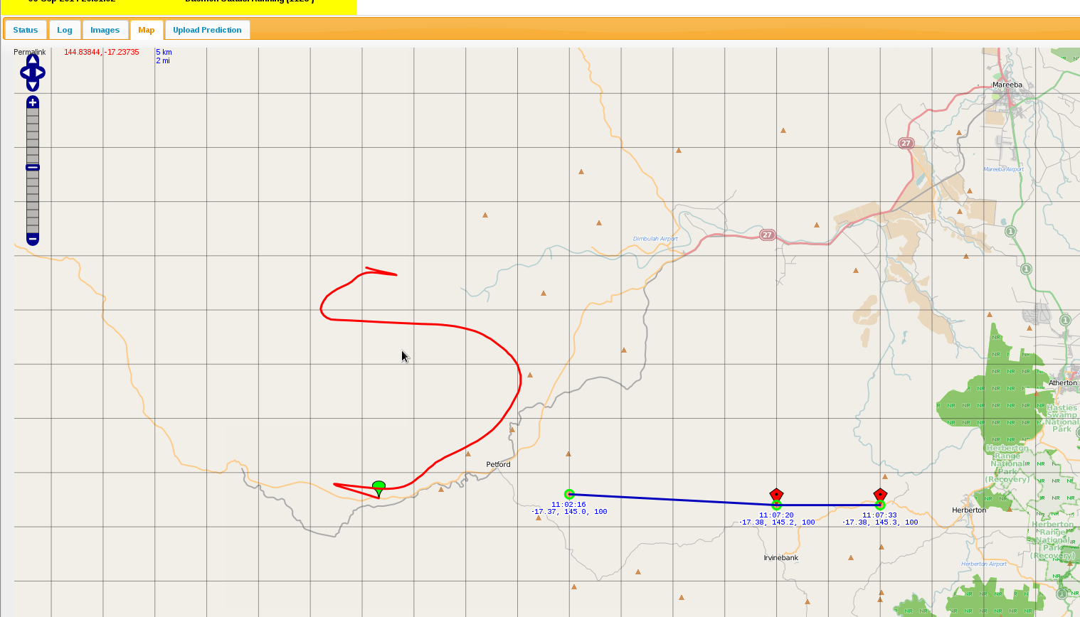
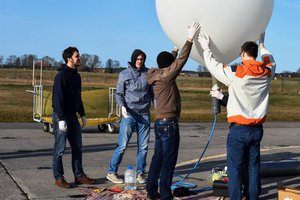
The aim of this project is to send a custom made payload 27km up into the Stratosphere and then recover it. The payload is to take measurements and send to the groundstation. Data to be transmitted during the flight is:-
* Air Pressure, Internal and external temperature
* System health stats
* GPS Co-Ordinates
* Photos captured by the 640x480 camera - then sends down to groundstation
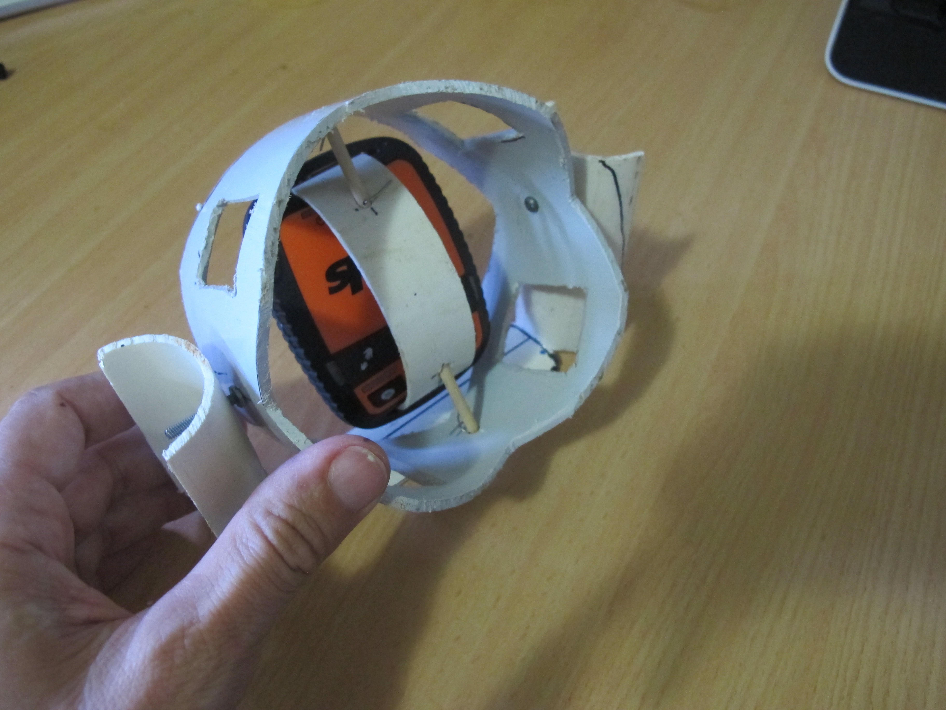
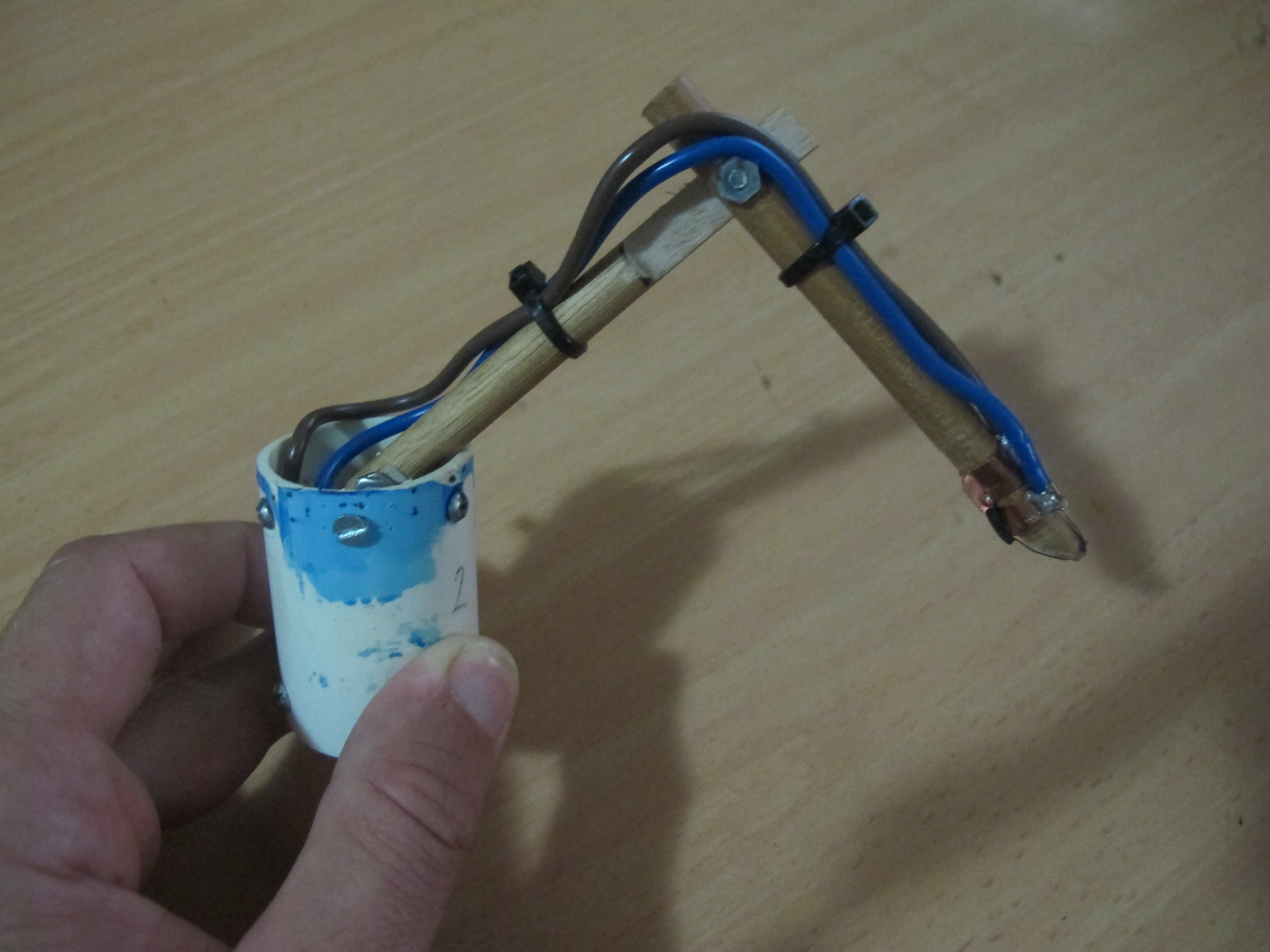
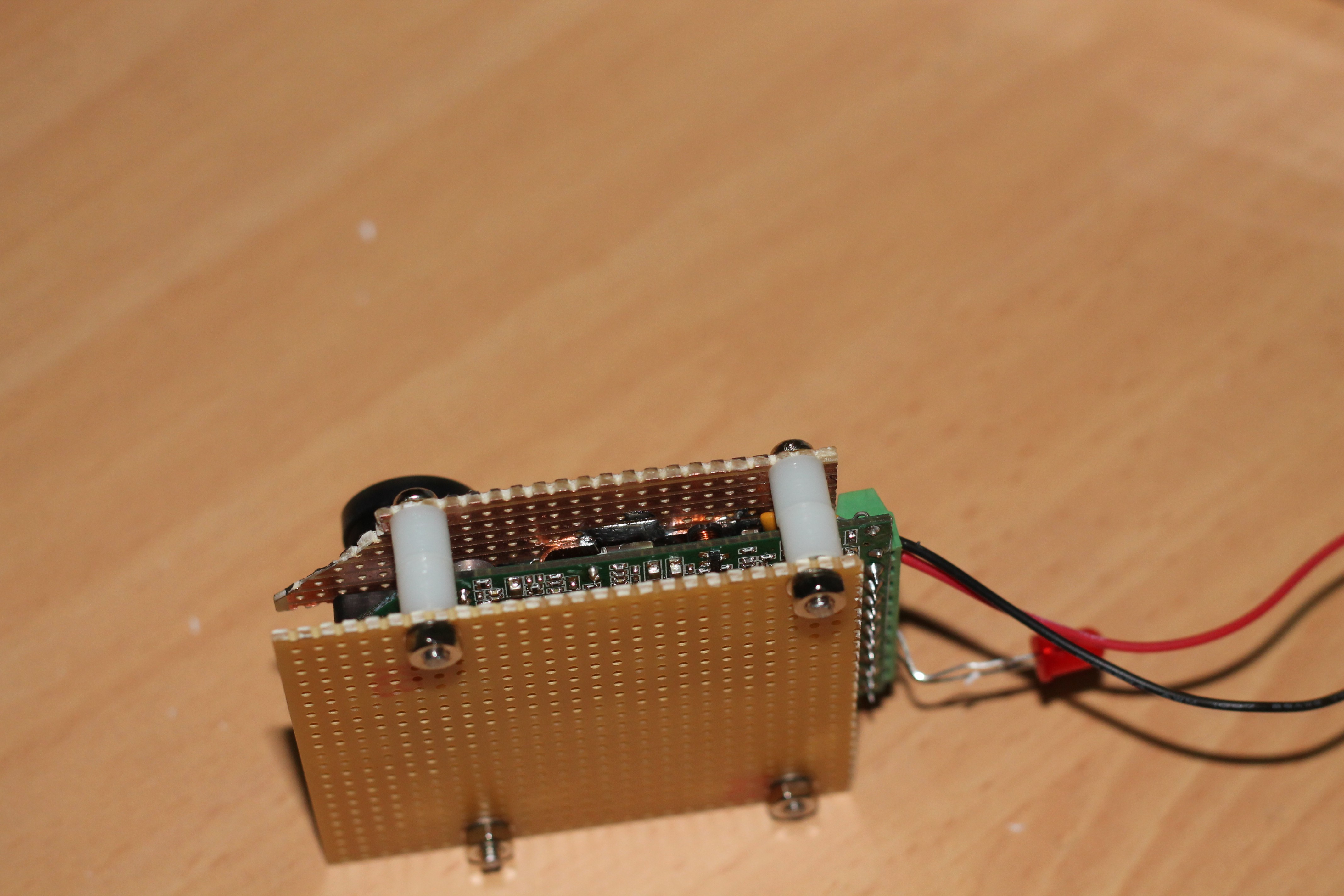
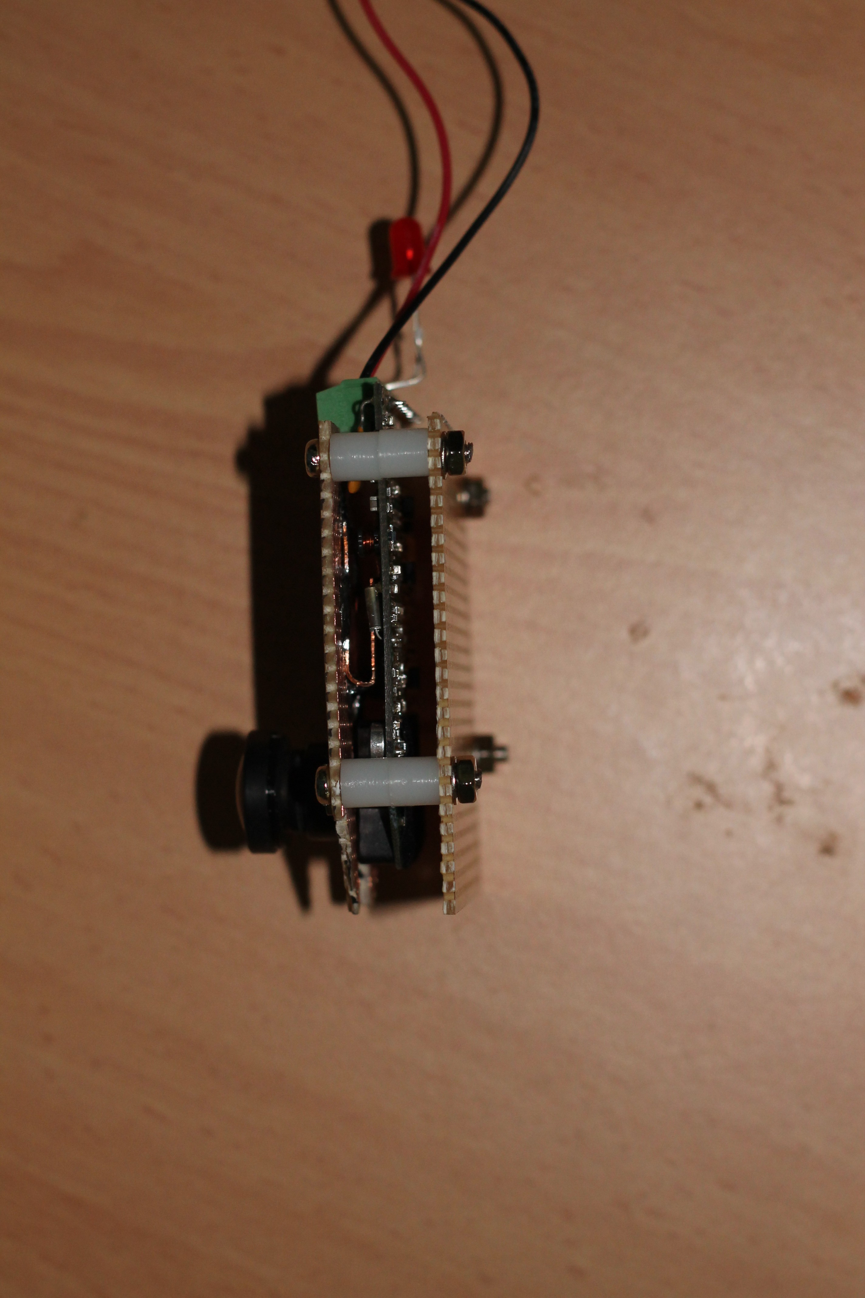
Short Introduction to Hardware
Here is a quick 2 minute video introduction of the main components of this project.
What makes this project "different"
The project is a little different from other "High Altitude Balloon" (HAB) projects because I have attempted to stream key data (including images) down the wireless link to the groundstation. The Groundstation (BBB) has an inbuilt webserver and a WIFI stick, so it can act as an AccessPoint. This allows one to connect to the groundstation and view all the HAB data on a tablet or mobile phone using a web browser! One cool thing I really wanted to do (but can't at present due to budget constraints) is to pair up Google Glasses or similar to the GroundStation so that all Payload information is viewable "hands free".
A lot of work has gone to make the tracking of the balloon payload as easy as possible and to provide as much "useful" data to the user. A rich and easy to use web interface is one of these features. There are many cool things that the web interface provides. It is able to use the GPS co-ordinates of the mobile phone and the GPS co-ordinates of the HAB payload and determine the approx distance and bearing. The web interface provides alerts when certain criteria are met, e.g. no heartbeats received in the last 5 minutes, or GPS on-board has less then 4 satellites.
There has been a lot of problem solving
This project has been particularly challenging because the RFD900 modems didn't work as well as expected and so led to the creation of a new branch of the RFD900 software to include ACK functionality - https://github.com/joeman155/Sik
In addition to RFD900 difficulties, the Xmodem libraries that I used on the Ardunio had some errors that caused problems during image downloads. Some fixes were made to these.

 roberts.trops
 Chuck Buckley
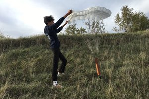
 Yohan Hadji
 joseph