 Sky Carter
[A CLASS PROJECT.]
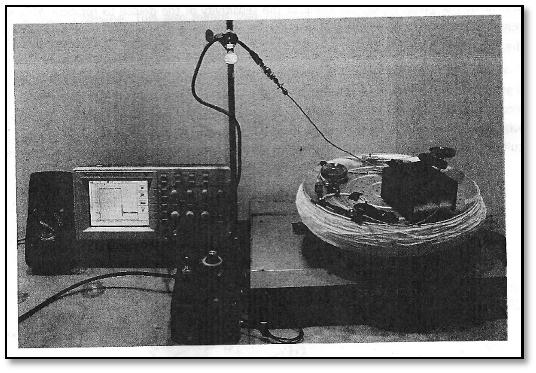
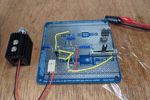
+MATERIALS:
- 1 aluminum mounting platform (the pizza pan!)
- 12 Chicago screws
- 2 FC/FC adapters
- 1 plastic loop form or wheel for mounting the fiber optic cable
- 1 100m single mode fiber optic cable with FC/UPC connectors
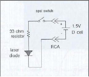
- 1 1.3 um analor IR laser ,fiber mountable, w/ ON/OFF switch
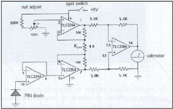
- 1 fiber mountable PIN diode deector / amplifier combo w/ zero control and 9V battery
- 1 multi-meter, 1MOhm input impedance
- 1 2x2 fiber optic coupler, single mode, w/ FC/UpC connectors
- 1 D Battery power supply
- 1 Phase controller (wheel) and mount
- 10 sets mounting clips and 6-32 screws
- (optional) rubber feet
(Special thanks to Skyhunt for easy assembly.)
===
The Sagnac Effect & the Journey of the Laser Light
(Go to Wikipedia for more information on the Sagnac Effect!)
-
The Sagnac Effect occurs when a laser light is split, and both beams are made to go the same path, but in different directions, in order to make the "ring". On return, however, both beams exit through the same door, but their collision causes interference - if both exit via a slit on a piece of paper, for instance, one would see overlapping hills and troughs of light, bright and dark bands rippling from the exit.
The Fun Part: So, when the platform that these lights are mounted upon rotates, the two beams shift, causing variations in the interference patterns. To measure the change from their initial position to their final position from each other, is to measure how far the vehicle with the gyroscope moved from their own default position. If a fighter-jet were to tip its nose downward by say, 5 degrees, the incredibly-sensitive gyroscope's lasers would shift, and the reading would come back to the pilot exactly (or almost exactly) how far they'd moved.
-
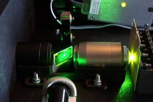
So, our laser light is beamed through the fiber-optic cable via the 1300nm IR laser, 1mW output - a cable composed on the inside of mirrors. The length and number of loops is directly responsible for the sensitivity of the gyroscope! The two wheels that control the phase of the light signal are simply smaller, additional loops that, when moved in a certain direction, help to stabilize the default position of that light (assumed 0) .
From there, the light is boosted by the PIN photo-diode amplifier, and likewise the "exit", where the acting interferometer (Multimeter or O-scope) picks it up and displays it.
--
Edit: Unfortunately, I'm out of time to put up a working video of the LRG's appearance at the Design Symposium, Spring 2014, but will definitely try for more pictures.
==
20140820 Wednesday: Equations
[From the Gyro Report]
Theory of Operation
-
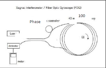
The Sagnac interferometer/FOG works by having a light beam from a laser split into two light beams that travel in opposite directions, and are joined back together by a coupler. The difference in angular velocity between the two light beams causes different phase angles that are detected by the photo-diode. The photo-diode outputs a voltage dependent on the phase difference between the two light beams.
Δt = 4ΩA/c
2 , Δ fringe = 4ΩA/c
λ Sensitivity equation (for gyroscope)
Fiber-optic cable = 100m, radius (r) =0.16m, 100 turns ≈ 1 m circumference
360°/s:
1. Angular velocity (Ω) v/r = 6.25
2. Area (A) = 0.08m^2 * 100 = 8.04m^2
3. C = 3 * 10^8 m/s
4. Λ 1.3 * 10^6m^2
Δ fringe = 0.515, 360/(0.515 * 2) = 349.5°/s out of phase to in phase in rotation
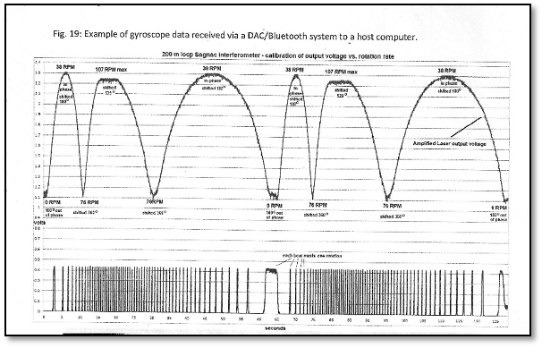
Maximum voltage ≈ 850mV
Sensitivity = 349.5/850 = 0.41°/s/mV or .4°/s for 1mV on a meter.


 Alan Green
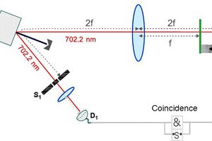
 esben rossel
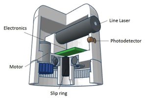
Adam,
Thank you very much for the practical solution to this problem. I first read about the Sagnac effect back in the 1970's or 80's. At that time it was too expensive to try it. Every five years or so, I look again. I followed the large ring laser experiments and was happy when people tried to measure the earth's rotations much more precisely. Then things sort of stopped. About ten years ago I tried to see if ring lasers could be used to measure changes in the the earth's gravity, since the changing gravitational potential from the sun (mostly) and moon and earth tides and local gravity effects will change the rate of clocks at different locations, and should have an effect on a ring laser as well. It has been a long time, and my access to those memories is dim right now.
My immediate reaction to what you have done, is two things - First I was looking at km long fiber transceivers and they were not too expensive. Second, I spend a lot of time with interferometry for gravitational sensors and precise possitioning and sensor array imaging. They all rely on precise measurement of voltages and currents. So if you simply put in a nanovolt resolution, you can easily track the rotation of the earth. 15 degrees per hour is 0.004167 degrees per second. That is a factor of 1000 better than your millivolt, or a microvolt resolution. Check my math, it is the middle of the night and I have been working for 18 hours. I get a bit fuzzy.
Let me encourage you to try this a bit more. I just checked and my intuition about gravitational time dilation (red shift in the article) is correct. See this paper http://citeseerx.ist.psu.edu/viewdoc/download?doi=10.1.1.729.2761&rep=rep1&type=pdf
You might be able to make a triple of ring lasers that can determine changes in the local vertical vector over time. If you are right and all you need is a better sensor for the interferometry state.
I have been working on ways to use low cost approaches to gravimeters. But I have had to sift through thousands of alternatives in detail. If I can get a ring laser built, and see its output, I can probably use several methods to squeeze another couple of orders of magnitude beyond jus using a better voltage sensor. A multimode fiber can carry hundreds of channels, Just two or three can be used like a vernier to get another order of magnitude. I was working on a low cost way to put tens of thousands or millions of channels through a fiber. It is hard for me to do problems where I have never seen the actual devices. A single experiment allows me to focus more than 50 working years onto a single problem, or more often a whole series of related problems that are ripe for change.
If you are still interested, I would be happy to chat with you. I was trying to buy transceivers, fibers the other day because the low cost 10 Gbps ethernet and related fiber technologies can probably be adapted to precise measurements. I need a few interferometers for positions sensing. If the readouts are electronic and spatially encoded, that is another order of magnitude for my other things.
LIGO is at 10^-21 meters of displacement per meter of travel of the light. But they are only operating at 16384 sps at the end of a long chain of hacked together parts. Their subsystems are much more sensitive to earth-based gravity changes, and can operate now in Msps, and fairly easily pushed to Gsps. The importance of high sampling rates is the debugging. There are LOTS of noise sources. You have to localize them in time and space, then eliminate them. So using arrays and time of flight correlation methods that can be used off the shelf from radio astronomy and radar and other areas. One can incrementally push through ten or 15 orders of magnitude. LIGO did it and every piece of their project was SO expensive! We should be able to replicate that on a desktop now with atom interferometers and better, cheaper sensors and better use of data. I throw terabytes of data at problems that others only measure a single value. Things move when you throw lots of data at them.
Richard Collins, The Internet Foundation