Wilcox Gay A46 Internet Radio
A 'basket case' antique set with working audio amp, shot RF stages (mice). Turn it into a Raspberry Pi-based internet radio!
A 'basket case' antique set with working audio amp, shot RF stages (mice). Turn it into a Raspberry Pi-based internet radio!
To make the experience fit your profile, pick a username and tell us what interests you.
We found and based on your interests.
|
Portable Network Graphics (PNG) - 586.49 kB - 11/27/2017 at 03:46 |
|
|
WilcoxGay Schematic.pdfProto1 schematic (PDF)Adobe Portable Document Format - 234.62 kB - 08/06/2017 at 05:00 |
|
|
Assembly.pdfProto1 PCB stuffing guideAdobe Portable Document Format - 134.63 kB - 08/06/2017 at 04:59 |
|
|
Top View.pdfProto1 PCB top viewAdobe Portable Document Format - 53.19 kB - 08/06/2017 at 04:59 |
|
|
Bottom View.pdfProto1 PCB bottom viewAdobe Portable Document Format - 75.82 kB - 08/06/2017 at 04:59 |
|
|
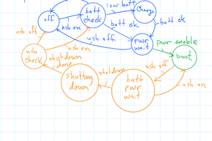
Oh, yeah, one thing to mention - the SHUTDOWN state has a flaw! I'm not sure what to do here, actually. The flaw is that if the PIC negates the "I want you to keep running" signal to the Pi, it then waits for the Pi to negate the "I am running" signal. But, if the Pi never responds by negating that signal, the power controller will just sit in SHUTDOWN state indefinitely. I'm not sure what to do, though! I don't want to gank power to the Pi (could corrupt the flash card) yet, really, I'm not sure what else to do... I don't like the fact that the power controller assumes that the Pi will always behave ...
With the hardware ready (as far I as knew) the next step was to start on the PIC MCU code that interfaces to the Raspberry Pi. In essence, there are really three tasks to be handled by the PIC:
I was able to tackle the first item, and I'm quite satisfied with the result. As I've mentioned previously, my power controller is heavily based upon the work of James Lewis, aka the Bald Engineer. I didn't use an Arduino, of course, and I ended up implementing a slightly different state machine - but for the most part it's the same idea. In short:
I've tested this quite a bit with various scenarios - I won't say it's bulletproof, but for the most part seems to be working well. Again, not my idea, so I'm more worried about my implementation than the whole concept itself!
I have implemented the second item, I2C slave, but yet to test it. I need to play with the Pi now to send some I2C messages and see if (how?) the PIC responds. In the meantime I've read a ton of stuff on the intrawebs about how the microchip I2C slave code is perhaps not-so-great, and/or how the I2C peripheral itself isn't so perfect when in slave mode. Oh joy.
The third task, WS2811 pixel control, should have been easy - as I did this already in my Rubidium Timebase project. However, for some reason it's not working... Grrrrrrrr!
But for now, I'm happy that I have a Pi that powers up and down (safely) when I turn the "power switch" on the old tube set.
For anyone following along, the power domains are:
The PIC micro is powered from constant 5V, and its main job is to manage the power to the R Pi Zero W - removing supply only after shutdown is complete. The mechanism for this is inspired by the (excellent) writeup by James Lewis on a Raspberry Pi Soft Power Controller circuit. When the volume knob power switch is turned on, the PIC detects the filament voltage via optocoupler U1 and applies V5P to the R Pi. When the filament voltage goes away (volume knob power switch turned off) the PIC will assert the GPIO pin to the process running on the Pi to request a shutdown, and then manage the V5P rail accordingly.
Sure, it's silly to have both the hardwire control for power management and the I2C link for the knob rotation info ... but it's a heck of a lot easier to debug the hardwire interface, and I can just steal the Pi side process code rather than having to worry about duplicating that functionality in I2C land merely in order to get the R Pi running... Maybe I'll migrate it all to I2C in the future. But I suspect that this will be another case of "the working is the enemy of the planned".
So, next step is to get some rudimentary code written for the PIC to implement filament voltage detection and power management handshake stuff, and throw in the Neopixel driver stuff too (reused from 10 MHz Rb Standard project) because who doesn't like a status LED?
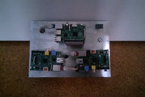
So the PCB came back and I proceeded to stuff it and do some basic tests - not such a complicated circuit really, but wanted to be sure I could switch on/off the Rpi Zero W power with the USB load switch. Check.
I stopped dithering on the tuning knob encoder and realized that I'd free up a ton of space on the chassis deck if I merely replaced the tuning condenser with a pot. I took a scrap piece of aluminum and bored a hole for a potentiometer at the right position and that was all it took. So, now the tuning dial moves 300-ish degrees, the same as the pot - and the angle is just a very simple voltage reading from the ADC. Easy-peasy.
I removed some no longer used original components from the radio chassis underdeck, too. That made space for the 120V to 5V supply that will feed the retrofit PCB with a constant 5V. More on power domains in the following log entry.
Back to the A46 internet radio update. In the intervening time, I decided to go the route of removing the tuning capacitor and replace it with a potentiometer, as the tuning mechanism in the radio readily supported that. I had to fabricate a quick and dirty bracket to hold the pot in position, but that was a simple matter of a scrap bit of aluminum and a few minutes work with a bench vise and a hammer. Therapeutic, even..
So, pot in place and tuning dial reassembled, attention turns to the electronics again. I'm a fan of the PIC18F44K22 TQFP44 device as it's easy to solder and has plenty of processing power for what I need it to do - which in this case is pretty much just two things: 1) be an I2C slave to the Raspberry Pi Zero to report position of the tuning, band, and (optional) volume controls and 2) manage the power to the Pi.
Schematic and board are complete, but the board isn't yet constructed nor tested..
I have taken a number of side-trips since posting this project. Scout activities and a few older projects got worked on (10 MHz Rb Oscillator controller; RS422 Pinewood Derby link; futzing about with the HD6309 SBC). As with a lot of my projects, this one is definitely "event driven" - the melting snow (next week!) will turn my thoughts to being able to relax on my front porch and listen to a ball game, or NPR, or some music.
Of course, to simply house an RPi internet radio into a pre-existing wooden box isn't much of a project. The challenge here, and I use that term generously, is to keep it looking as "stock" as possible. It's a really pretty wooden AM radio that I bought in the hopes of restoring it to working condition. That's not going to happen - there just aren't enough Wilcox-Gay donor sets around to scavenge parts from. At this point, I've resurrected and reworked the audio stages, so all I need is to provide power to the Pi and work out how to "tune" the different internet radio stations. I'll keep it simple and just re-define the tuning so that the complete arc of tuning (about 300 degrees?) is divided into, say, 10 different zones. Each zone corresponds to an internet radio pre-set.
I'd like to use the same tuning mechanism, which unfortunately is not the typical belt-pulley arrangement from a knob to the tuning cap. Rather, the tuning cap has a large diameter (about 6 inches or so) wheel attached to it, and the tuning control knob turns a small wheel which rubs against the edge of the large wheel, thereby providing a sort of vernier drive to the tuning cap. It would be more mechanical surgery than I'd like to rip out the tuning cap and fit a potentiometer there, so I'm favoring a solution that simply re-uses the existing tuning cap. I have thought of two ways to do this.
Method one is to simply use the tuning cap as part of an R-C oscillator, and then measure the frequency to determine tuning position.
Method two is to use the tuning cap as a timing element -- measure how long the voltage across the cap takes to reach some voltage threshold while it's being charged with a constant current source.
Both are pretty simple, but I think that the oscillator approach is the easiest to implement on the Pi. I've seen that even Python has a time module that includes the ability to pulse-count. As a fallback, I could always use a trusty Microchip PIC to do the frequency measurement (using either method) and interface the PIC to the Pi using I2C or SPI. More complicated, but might open doors to some other possibilities. I'd like to have a few WS2812 status LED as backlight, to help indicate status of the radio, for instance. That might be easier to do with a PIC as the "middleman".
Open to suggestions...
Create an account to leave a comment. Already have an account? Log In.
Become a member to follow this project and never miss any updates

 Craig Hissett
 Tobias W.
 Paul Crouch
 ESharpAxe