Close
0%
0%

Inexpensive Composite Propellers/Rotors

How to make inexpensive propellers using mostly hardware store materials and a CNC router

Similar projects worth following
This project goes through all the steps on how to make a composite propeller for as little as $20-$40 dollars.

Overview

When starting #Goliath - A Gas Powered Quadcopter, one of the goals was to use off the shelf hardware. After looking at propeller/rotor from traditional aircraft suppliers two issues became readily apparent. The first issue was that the cheapest rotors start at about $300, so a complete would be over a grand. This would have overly expensive for a prototype vehicle that broke three rotors in the first 50 tests. The second issue was the the designs are closed source. The buyer is expected to provide the manufacturer a engine/airframe combination and the manufacturer designs the rotor to match, and does not provide the buyer the details.

The goal of this project was to provide the tools and design instructions for other makers to build and/or design their own inexpensive open-source propellers/rotors. These goals have been met and the project documentation allows the user to build their own propellers/rotors for as little as $20-$40.

Design

There are a couple of rotor designs included in the github repository available for anyone to build. However if you need to design your own propeller from scratch, the repo has what you need as well. The first step is to determine the necessary propeller/rotor characteristics. The Rotor Blade Element Analysis (RBEA) code can help in designing the right propeller characteristics. While it's not required, a basic understanding of blade element theory is helpful in applying the code. Once you've found a design that can provide the required thrust at the desired power and RPM setting, a CAD model can be built for generating the CNC tool paths.

Construction

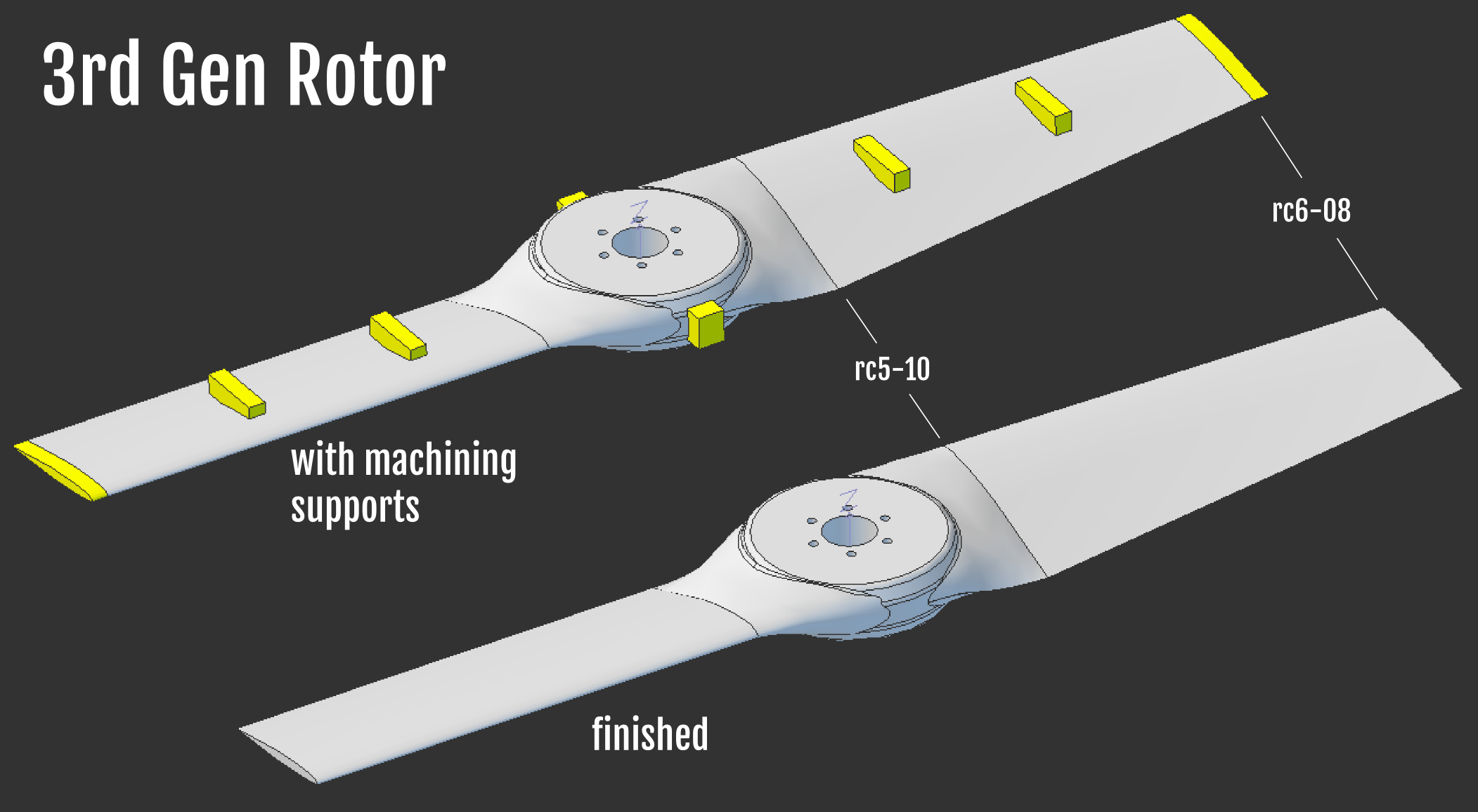
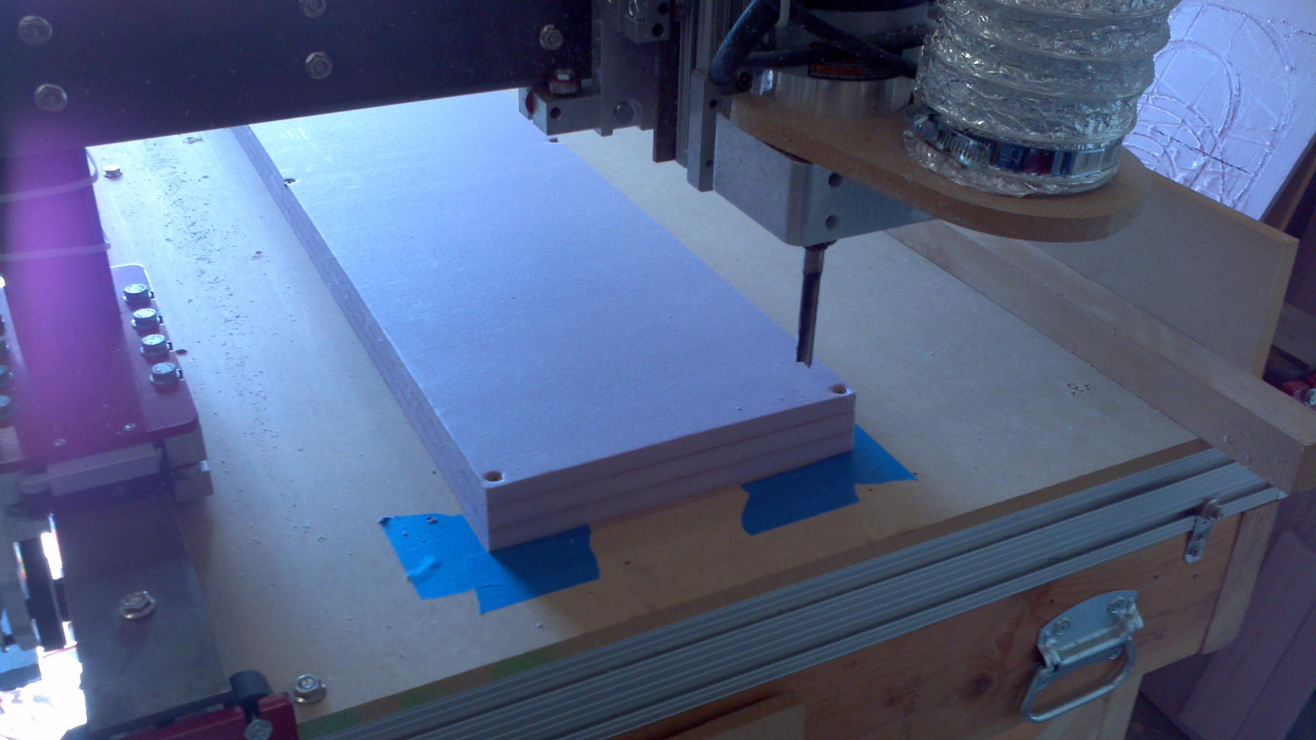
The propellers/rotors are built using a foam core composite method. This type of method has been used by model aircraft builders to build lightweight wings. Typically in the past, the foam cores are constructed using hot-wire cutters and 2D airfoil templates to guide the hot-wire. This technique is limited as it can be difficult to impossible to build complex or twisted cores.

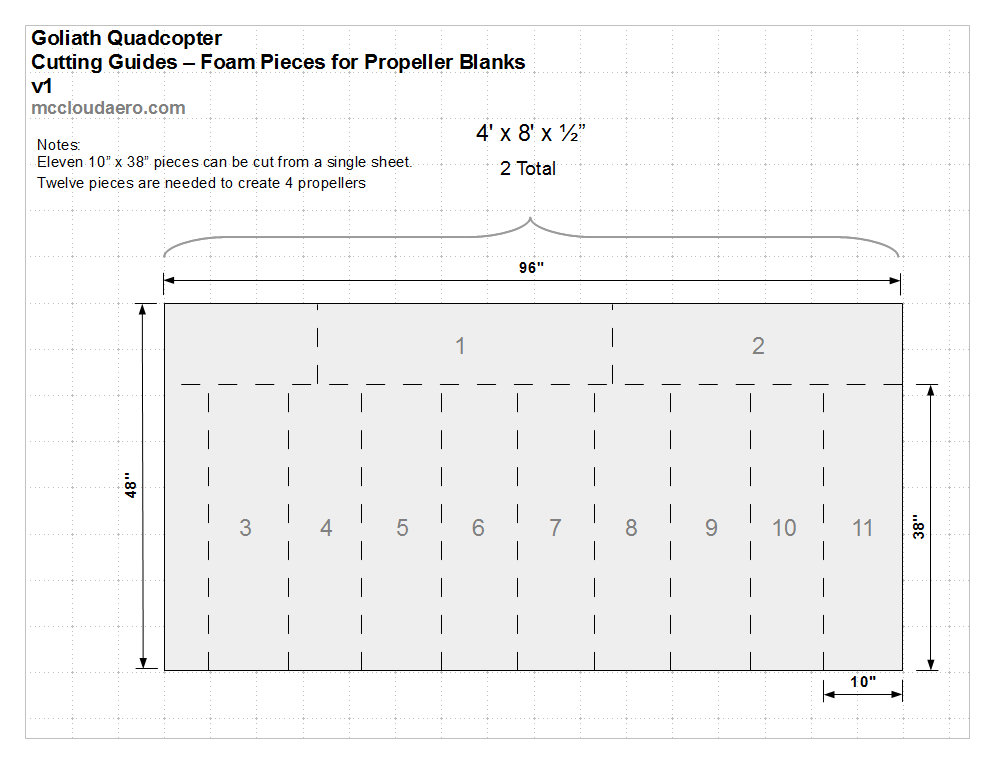
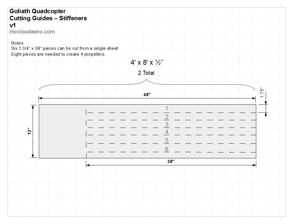
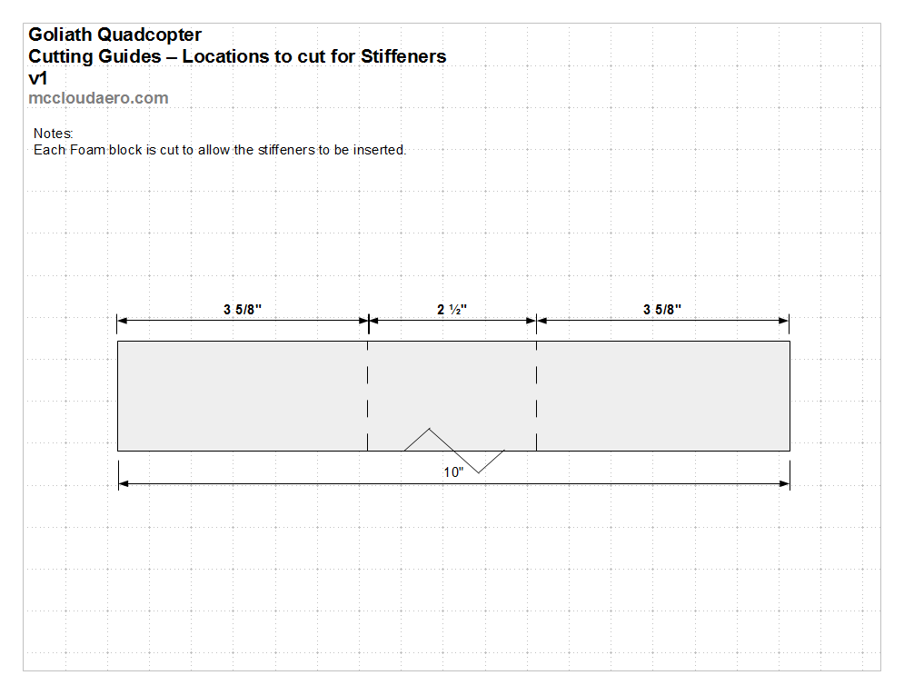
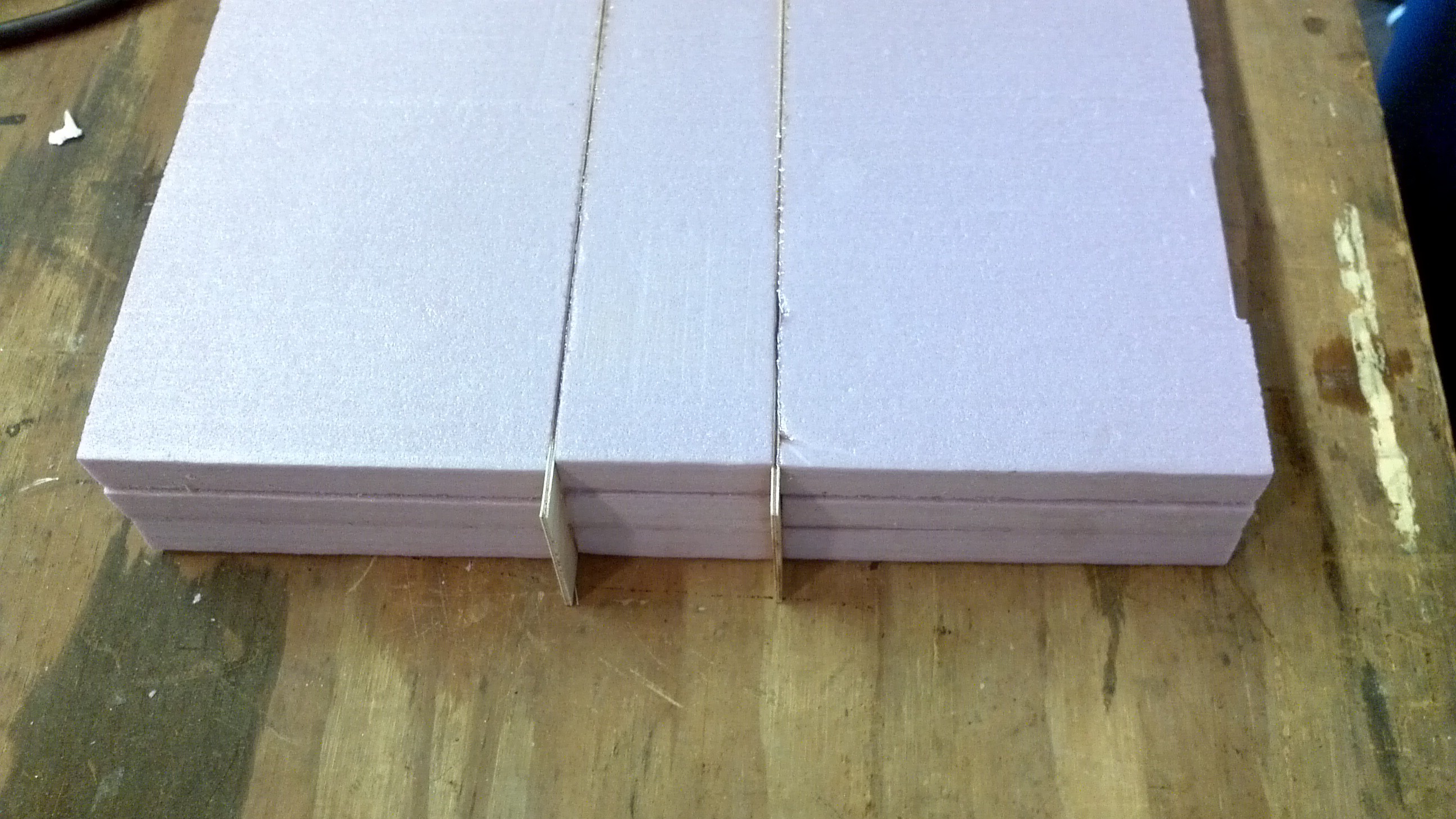
CNC routers allow complex cores to be built easily and have features that can't be done with hot-wire cutters such as embedded stiffeners. This project outlines the process of how to construct inexpensive foam core composite propellers/rotors.

  • 2 × Foam Insulation Board (4' x 8' x 1/2") Corning Foamular (pink) or Dow Stryofoam (blue)
  • 1 × Spray Adhesive Loctite High Performance 200
  • 2 × Birch Plywood (48" x 12" x 1/16") Model Aircraft Plywood
  • 1 × Fiberglass 9 oz
  • 1 × Epoxy Resin

  • 3rd Gen Rotor Design

    Peter McCloud03/24/2017 at 03:25 0 comments

    The design for the 3rd gen rotor has been finalized and is shown below. The upper portion of the picture shows the rotor with the machining supports present. This is what the rotor looks like coming out of the CNC Router. The lower portion of the images shows the finished rotor with the supports removed. The airfoils for the tip and the root are highlighted.

  • RC series Airfoils

    Peter McCloud03/02/2017 at 05:09 5 comments

    The previous rotor designs used generic NACA 2412 airfoils. These airfoils were developed over 80 years ago, but they are well documented and good general purpose airfoils. However to get the most thrust, airfoils specifically designed for rotors are required. Searching around led to the RC series of airfoils

    RC series airfoils

    The RC series of airfoils are specifically designed for rotorcraft applications. The naming scheme is RC(X)-YY where X is the number in the series and YY is the airfoil thickness in percent chord. Two of the airfoils, designed for the inboard section of rotor blades are the RC(4)-10, RC(5)-10. Data for these airfoils is found in:

    NACA TP 3009 Aerodynamic Characteristics of Two Rotorcraft Airfoils Designed for Application to the Inboard Region

    The other airfoil is the RC(6)-08 airfoil, designed for rotor tips. Data for this airfoil is documented in:

    NASA TM 4264 Aerodynamic Characteristics of a Rotorcraft Airfoil Designed for the Tip Region of a Main Rotor Blade

    Applying the new airfoils

    Previously the rotor.py code was only written to use a single airfoil for the entire rotor. Recent updates allowed using two different airfoils, one a the tip and the second at the root. Changing the tip airfoil from the NACA 2412 to the RC(6)-08 means a 25% reduction in the chord. Since the bending moments are low at the tip, the thinner section doesn't affect the structural strength significantly.

    Changing the root airfoil from the NACA 2412 to the RC(5)-10 airfoil means a 17% thinner airfoil. It may not seem like much, but the bending strength scales by the thickness cubed. Keeping the chord constant and changing from a 12% to 10% thick airfoil means a 42% reduction in bending strength.

    To keep a similar strength with the thinner airfoil, the root chord will be increased from 4.5 to 5.4 inches to keep the overall thickness the same at the root. This leads to a negligible decrease in aerodynamic efficiency, but a big difference in the structural design.

    So how big is the difference?

    Rotor hover performance is measured by Figure of Merit (FM) vs. Efficiency. Hovering isn't doing any useful work so efficiency doesn't really apply. The FM is the ratio of the required power vs. the ideal required power. The previous rotors had a FM of about 60%. Analysis suggests the new rotors using the RC airfoils will have a FM of 80%.

  • Rotor Blade Element Analysis (RBEA)

    Peter McCloud02/24/2017 at 04:20 0 comments

    Code Updates

    Recently, the rotor designs were re-visited to double check some of the design assumptions. In the process the code was polished up and some improvements were made.

    Bug Fixes

    Found that the code would not converge for some cases and the user wouldn't know. Not so much a bug as poor programming. Added logic to notify the user if the case doesn't converge

    Improvements

    Broke out the inputs into a file (inputs.txt), keeping the code cleaner. Additionally switched to using splines for the airfoil data instead of fits done in a spreadsheet. Added support for Mach and alpha airfoil coeffs vs just alpha.

    Additions

    Code for calculating blade moments

    Python Code (repo location)

    import sys
    import math
    import numpy as np
    import scipy.interpolate
    # Rotor Blade Element Analysis
    # Python Script for determining Rotor Performance using Blade Element Theory
    # Definitions
    # theta - The physical angle the airfoil is rotated from the plane of rotation
    # phi	- The change in flow angle due to the induced airflow.  Makes the angle of attack smaller
    # alpha_rad	- The effective angle of attack the airfoil experiences
    # alpha_rad + phi = theta
    pi = math.pi
    # Read inputs file
    execfile('inputs.txt')
    # Determine airfoil method
    try:
     airfoil_name
    except:
     # airfoil_name is not defined, see if tip & root airfoil names exist
     try:
      tip_airfoil_name
     except NameError:
      print 'Neither airfoil_name nor tip_airfoil_name in inputs file'
      print 'Exiting!'
      sys.exit(1)
     else:
      # tip_airfoil_name exists, see if root_airfoil_name exists
      try:
       root_airfoil_name
      except:
       print 'root_airfoil_name is not defined in the inputs file'
       print 'Exiting!'
       sys.exit(1)
      else:
       airfoil_type = 'blended' 
    else:
     airfoil_type = 'single' 
    # Read airfoil data
    if airfoil_type == 'single':
     airfoil = np.loadtxt('./airfoils/'+airfoil_name+'.dat',skiprows=1,delimiter=',')
     # Create splines
     mach_data = airfoil[:,0]
     alpha_data = airfoil[:,1]
     cd_data = airfoil[:,2]
     cl_data = airfoil[:,3]
     cm_data = airfoil[:,4]
     # Determine Mach Range
     if min(mach_data) == max(mach_data):
      # Single Mach Number present, Create 1D splines
      airfoil_data_type = '1D'
      cd_spline = scipy.interpolate.splrep(alpha_data,cd_data)
      cl_spline = scipy.interpolate.splrep(alpha_data,cl_data)
      cm_spline = scipy.interpolate.splrep(alpha_data,cm_data)
     else:
      # Multiple Mach Numbers present, Create 2D splines
      airfoil_data_type = '2D'
      cd_spline = scipy.interpolate.bisplrep(mach_data,alpha_data,cd_data)
      cl_spline = scipy.interpolate.bisplrep(mach_data,alpha_data,cl_data)
      cm_spline = scipy.interpolate.bisplrep(mach_data,alpha_data,cm_data)
    else:
     # Tip
     airfoil = np.loadtxt('./airfoils/'+tip_airfoil_name+'.dat',skiprows=1,delimiter=',')
     # Create splines
     mach_data = airfoil[:,0]
     alpha_data = airfoil[:,1]
     cd_data = airfoil[:,2]
     cl_data = airfoil[:,3]
     cm_data = airfoil[:,4]
     # Determine Mach Range
     if min(mach_data) == max(mach_data):
      # Single Mach Number present, Create 1D splines
      tip_airfoil_data_type = '1D'
      tip_cd_spline = scipy.interpolate.splrep(alpha_data,cd_data)
      tip_cl_spline = scipy.interpolate.splrep(alpha_data,cl_data)
      tip_cm_spline = scipy.interpolate.splrep(alpha_data,cm_data)
     else:
      # Multiple Mach Numbers present, Create 2D splines
      tip_airfoil_data_type = '2D'
      tip_cd_spline = scipy.interpolate.bisplrep(mach_data,alpha_data,cd_data)
      tip_cl_spline = scipy.interpolate.bisplrep(mach_data,alpha_data,cl_data)
      tip_cm_spline = scipy.interpolate.bisplrep(mach_data,alpha_data,cm_data)
     # Root 
     airfoil = np.loadtxt('./airfoils/'+root_airfoil_name+'.dat',skiprows=1,delimiter=',')
     # Create splines
     mach_data = airfoil[:,0]
     alpha_data = airfoil[:,1]
     cd_data = airfoil[:,2]
     cl_data = airfoil[:,3]
     cm_data = airfoil[:,4]
     # Determine Mach Range
     if min(mach_data) == max(mach_data):
      # Single Mach Number present, Create 1D splines
      root_airfoil_data_type = '1D'
      root_cd_spline = scipy.interpolate.splrep(alpha_data,cd_data)
      root_cl_spline = scipy.interpolate.splrep(alpha_data,cl_data)
     root_cm_spline...
    Read more »

  • Rotor Repository

    Peter McCloud07/22/2015 at 05:08 0 comments

    A new rotor design github repository is being created to store the rotor information separate from the Goliath design repository. This new repository will contain the design files for the previous rotor design (alpha) and the new rotor design (beta). The repository will also contain the python program developed to predict the rotor thrust.

  • Documentation

    Peter McCloud10/23/2014 at 11:15 0 comments

    I'm starting a separate project for the propellers that I've been building for #Goliath - A Gas Powered Quadcopter. As Goliath has progressed, the documentation of all the elements is becoming a bit unwieldy and the rotors are a project on there own. The plan is to more thoroughly document the rotors here than they have on Goliath's project log and also describe the project in more generic terms for anyone to apply towards their own applications.

View all 5 project logs

  • 1
    Step 1

    Getting Started

    If you're re-creating the propellers for Goliath, the shape has already been created and the g-code is available in the rotor design github repository.

    If you're making your own design, here's a brief overview of what's needed to create your own g-code. Note that the following steps are intended for a propeller that is 36" in diameter, 8" wide and 2" deep. If your propeller dimensions are different, you'll have to adjust accordingly.

    1. Design the propeller using your own tools or you can use the code contained in the repository. The critical data needed is the airfoil aerodynamic data and airfoil orientation at various chords.
    2. Using a CAD program, create a 3D model of the propeller/rotor using the inputs from your propeller design. Try to transition smoothly between profiles, to avoid sharp edges
  • 2
    Step 2

    Preparing the Material Blanks for the Router

    Cut the Foam Pieces

    Cut the foam sheet to sizes needed to build up the foam block. The propellers for Goliath use 10" x 38" pieces. To get the most out of the material use the cutting guides.

    Peel off the coating on both sides of all the pieces

    Glue the Foam Pieces Together

    Find a flat surface to lay the foam pieces on top of. To keep the foam block clean and to catch the over spray, lay down something to work on ( I typically use red rosin paper). Using the spray adhesive, glue the sheets together to make the foam block. To get the best bond, Loctite recommends spraying a medium coat on both surfaces, letting them sit for a minute, then press the two pieces together. A total of 3 pieces are used to create one foam block.

    Cut the Stiffeners

    Cut the birch plywood to create the stiffeners. They should be as long as the block and as wide as the foam block is tall. For Goliath, these stiffeners are 1 3/4" x 38". (Yes 3 times 1/2" does not equal 1 3/4", ask Dow or Owens Corning) Two stiffeners are used in each foam block. If you're using a table saw it can be a little tricky to cut the really thin plywood since it wants to slid under the fence.


    Add the Stiffeners to the Foam Block

    Cut the foam blocks where the plywood stiffeners will be added.


    Using the epoxy join the foam block back together with the stiffeners inserted.

  • 3
    Step 3

    Cut the Propeller Blank

    Tools: CNC Router with 1/2" and 1/4" router bits (flat)

    A) Attach the Block and prep the router

    Attach the blank to the spoilboard. When cutting with the half inch bit, there is an extra 3/4" on each side of the block, but make sure any screws stay within the 3/4" margin. Six screws are sufficient to hold down the foam, one in each corner and one in the middle of the each of long sides. Because of the margin, you don't have to mount the block perfectly square, but get it reasonably aligned, so you don't hit a screw. Since I'm doing at least four of these, I used painters tape on the spoilboard to do the alignment.

    B) Make sure you have the 1/2" bit in the router and set the zero point for the router. The g-code for the propellers on the repository assume the top of the material is at z=0. From the starting corner (shown) the edges are at x = -1 and y=-1 respectively.

    C) Run the router using the g-code for top, rough code.


View all 4 instructions

Enjoy this project?

Share

Discussions

99praneeth wrote 01/14/2019 at 15:27 point

HI,

this is regarding the gas drones, Recently i got a problem statement stating building a multi copter for lifting 30 kg payload initially we planned for battery powered drones but gave it up as it wasn't much suitable for lifting heavy payloads so it'll be help full if u help about the project like what is best possible way for lifting the payload the type of controlling system, the type of engine, power transmission to propellers, which is better the engine way or the battery method, the kind of propellers etc. 

  Are you sure? yes | no

Similar Projects

Does this project spark your interest?

Become a member to follow this project and never miss any updates